1
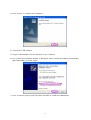
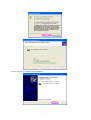
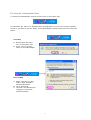
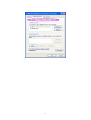
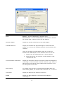
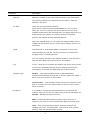
802.11g Wireless LAN Mini
USB Adapter
User Manual
Version: 2.0
(August, 2004)
COPYRIGHT
Copyright © 2004/2005 by this company. All rights reserved. No part of this
publication may be reproduced, transmitted, transcribed, stored in a retrieval
system, or translated into any language or computer language, in any form or
by any means, electronic, mechanical, magnetic, optical, chemical, manual or
otherwise, without the prior written permission of this company
This company makes no representations or warranties, either expressed or
implied, with respect to the contents hereof and specifically disclaims any
warranties, merchantability or fitness for any particular purpose. Any software
described in this manual is sold or licensed "as is". Should the programs
prove defective following their purchase, the buyer (and not this company, its
distributor, or its dealer) assumes the entire cost of all necessary servicing,
repair, and any incidental or consequential damages resulting from any defect
in the software. Further, this company reserves the right to revise this
publication and to make changes from time to time in the contents hereof
without obligation to notify any person of such revision or changes.
All brand and product names mentioned in this manual are trademarks and/or registered
trademarks of their respective holders.
Federal Communication Commission
Interference Statement
This equipment has been tested and found to comply with the limits for a
Class B digital device, pursuant to Part 15 of FCC Rules. These limits are
designed to provide reasonable protection against harmful interference in a
residential installation. This equipment generates, uses, and can radiate radio
frequency energy and, if not installed and used in accordance with the
instructions, may cause harmful interference to radio communications.
However, there is no guarantee that interference will not occur in a particular
installation. If this equipment does cause harmful interference to radio or
television reception, which can be determined by turning the equipment off
and on, the user is encouraged to try to correct the interference by one or
more of the following measures:
1. Reorient or relocate the receiving antenna.
2. Increase the separation between the equipment and receiver.
3. Connect the equipment into an outlet on a circuit different from that to which the
receiver is connected.
4. Consult the dealer or an experienced radio technician for help.
FCC Caution
This equipment must be installed and operated in accordance with provided
instructions and a minimum 5 cm spacing must be provided between
computer mounted antenna and person’s body (excluding extremities of
hands, wrist and feet) during wireless modes of operation.
This device complies with Part 15 of the FCC Rules. Operation is subject to
the following two conditions: (1) this device may not cause harmful
interference, and (2) this device must accept any interference received,
including interference that may cause undesired operation.
Any changes or modifications not expressly approved by the party responsible
for compliance could void the authority to operate equipment.
Federal Communication Commission (FCC) Radiation Exposure Statement
This equipment complies with FCC radiation exposure set forth for an
uncontrolled environment. In order to avoid the possibility of exceeding the
FCC radio frequency exposure limits, human proximity to the antenna shall
not be less than 20cm (8 inches) during normal operation.
R&TTE Compliance Statement
This equipment complies with all the requirements of DIRECTIVE 1999/5/CE
OF THE EUROPEAN PARLIAMENT AND THE COUNCIL of March 9, 1999 on
radio equipment and telecommunication terminal Equipment and the mutual
recognition of their conformity (R&TTE)
The R&TTE Directive repeals and replaces in the directive 98/13/EEC
(Telecommunications Terminal Equipment and Satellite Earth Station
Equipment) As of April 8, 2000.
Safety
This equipment is designed with the utmost care for the safety of those who
install and use it. However, special attention must be paid to the dangers of
electric shock and static electricity when working with electrical equipment. All
guidelines of this and of the computer manufacture must therefore be allowed
at all times to ensure the safe use of the equipment.
EU Countries Intended for Use
The ETSI version of this device is intended for home and office use in Austria,
Belgium, Denmark, Finland, France, Germany, Greece, Ireland, Italy,
Luxembourg, the Netherlands, Portugal, Spain, Sweden, and the United
Kingdom.
The ETSI version of this device is also authorized for use in EFTA member
states: Iceland, Liechtenstein, Norway, and Switzerland.
EU Countries Not intended for use
None.
CONTENTS
1 INTRODUCTION ............................................................................. 1
1.1
F EATURES .................................................................................................... 1
1.2
S PECIFICATIONS ............................................................................................ 1
1.3
P ACKAGE C ONTENTS ..................................................................................... 2
2 INSTALLATION PROCEDURE ..................................................... 3
3 CONFIGURATION UTILITY ......................................................... 9
3.1
W IRELESS C ONNECTION S TATUS .................................................................... 9
3.2
G ENERAL C ONNECTION S ETTING ................................................................. 11
3.3
WEP
AND
WPA E NCRYPTION ...................................................................... 14
3.3.1 WEP Setting ........................................................................................................... 15
3.3.2 WPA Setting .......................................................................................................... 16
3.4
A DVANCED S ETTING ................................................................................... 18
3.5
S OFTWARE AP M ODE .................................................................................. 19
3.5.1 AP Connection Status ............................................................................................. 19
3.5.2 AP General Connection Setting ............................................................................... 20
3.5.3 MAC Address Filter................................................................................................ 22
4 TROUBLESHOOTING .................................................................. 24
1 Introduction
Thank you for purchasing the 802.11g W ireless LAN Mini USB Adapter. This USB Adapter is
designed to comply with IEEE 802.11g W ireless LAN standard and easy to carry with the
Mini size. It is suitable for any Laptop or Desktop computers.
This adapter supports 64/128/256-bit W EP data encryption that protects your wireless
network from eavesdropping. It also supports WPA (Wi-Fi Protected Access) feature that
combines IEEE 802.1x and TKIP (Temporal Key Integrity Protocol) technologies. Client
users are required to authorize before accessing to APs or AP Routers, and the data
transmitted in the network is encrypted/decrypted by a dynamically changed secret key.
This adapter has built-in AES engine which ensure the highest degree of security and
authenticity for digital information and it is the most advanced solution defined by IEEE
802.11i for the security in the wireless network.
This adapter is cost-effective, together with the versatile features; it is the best solution for
you to build your wireless network.
1.1
Features
•
•
•
•
•
•
•
•
•
1.2
Complies with the IEEE 802.11b and IEEE 802.11g 2.4GHz standards.
Up to 54Mbps high data transfer rate.
Support 64/128/256-bit WEP, WPA (TKIP with IEEE 802.1x) and AES functions for high level
of security.
Supports Software AP function, which turns the wireless station into a wireless AP.
Complies with IEEE 802.11d country roaming standard.
Support the most popular operating system: Windows 98SE/Me/2000/XP/Server 2003.
Supports USB 2.0/1.1/1.0 interface.
Portable and mini-size design.
Suitable for Any Notebook or Desktop PC.
Specifications
•
•
•
•
Standard: IEEE 802.11g/b
Bus Type: USB 2.0 Type A
Frequency Band: 2.4000~2.4835GHz (Industrial Scientific Medical Band)
Modulation: OFDM with BPSK, QPSK, 16QAM, 64QAM (11g)
BPSK, QPSK, CCK (11b)
•
•
•
•
•
Data Rate: 54/48/36/24/18/12/11/9/6/5.5/2/1Mbps auto fallback
Security: 64/128/256-bit WEP Data Encryption, WPA (IEEE 802.1x with TKIP) and AES
Antenna: Internal Antenna
Drivers: Windows 98SE/Me/2000/XP/Server 2003
LED: Link/Activity
1
•
•
•
•
•
1.3
Transmit Power: 16dBm (Typical)
Dimension: 9(H) x 27(W) x 87(D)
Temperature: 32~131°F (0 ~55°C)
Humidity: 0-95% (NonCondensing)
Certification: FCC, CE
Package Contents
Before you begin the installation, please check the items of your package. The package
should include the following items:
•
•
•
•
One USB Adapter
One USB 2.0 Extension Cable (100 cm)
One Quick Guide
One CD (Driver/Utility/Manual)
If any of the above items is missing, contact your supplier as soon as possible.
2
2 Installation Procedure
Before you proceed with the installation, please notice following descriptions.
Note1: Please do not install the USB adapter into your computer before installing the software
program from the CD.
Note2: The following installation was operated in Windows XP. (Procedures are similar for
Windows 98SE/Me/2000/Server 2003.)
Note3: If you have installed the Wireless PC Card driver & utility before, please uninstall the
old version first.
Please follow below instructions to install the USB Adapter.
I. Install the Configuration Utility
A. Insert the Installation CD to your CD-ROM Drive. Execute the “setup” program.
B. If you want to install the software program in another location, click “Browser” and select
an alternative destination. Then, click “Next”.
3
C. Click “Continue Anyway” to finish the installation.
4
D. Click “Finish” to complete the installation.
II. Install the USB Adapter
A. Plug the USB Adapter into the USB port of your computer.
B. The “Found New Hardware Wizard” is displayed, select “Install the software automatically
(Recommended)” and click “Next”.
C. Click “Continue Anyway” and the system will start to install the USB adapter.
5
D. Click “Finish” to complete the installation.
6
III. Using the Configuration Utility
To setup the USB adapter, double-click the icon in the system tray.
For Windows XP, there is a “Windows Zero Configuration Tool” for you to setup wireless
clients. If you want to use the Utility of the USB adapter, please follow one of the ways as
below.
First Way
A. Double-click the utility
icon in the system tray.
B. Click “Yes” to use the
utility of the USB adapter.
Second Way
A. Right-click the icon and
select “View Available
Wireless Networks”.
B. Click “Advanced”.
C. Uncheck “Use W indows to
configure my wireless
network settings”.
7
8
3 Configuration Utility
The Configuration Utility is a powerful application that helps you configure the 802.11g
Wireless LAN Mini USB Adapter and monitor the link status during the communication
process.
The Configuration Utility appears as an icon on the system tray of W indows while the card is
running. You can open it by double-click on the icon.
Right click the icon, there are some items for you to operate the configuration utility.
Open Utility W indow
Select “Open Utility Window” to open the Configuration Utility tool.
Exit ZDW lan
Select “Exit ZDW lan” to close the Configuration Utility tool.
Before using the utility, you have to know some restrictions of the utility.
1.
If you want to connect to 11g (up to 54Mbps) network, please ensure to install the
adapter to PC or laptop with USB 2.0 interface. This adapter runs at lower performance
while you connect it to the USB 1.1/1.0 port of your computer instead.
2.
This adapter will work in 11b mode when the network type is in Ad Hoc mode. It is
defines by Wi-Fi organization. If you want to enable the data rate up to 54Mbps (11g),
please follow steps listed below.
A. Go to “Network Connections”.
B. Right Click the “Wireless Network Connection” and select “Properties”.
C. From the pop-up screen, click “Configure”.
D. Enter into “Advanced” page of the “Properties” screen.
E. Enable the setting of “IBSS_G_Mode”.
3.1
Wireless Connection Status
When you open the Configuration Utility, the system will scan all the channels to find all the
access points/stations within the accessible range of your card and automatically connect to
the wireless device with the highest signal strength. From the screen, you may know all the
information about the wireless connection.
9
Parameter
Description
Mode
Station – Set the USB adapter a wireless client.
Access Point – Turns the USB adapter to function as a wireless
AP. Please refer to Section 3.5 for the AP settings.
Network Adapter
Display the product information of the USB Adapter.
Available Network
Display all the SSID and Signal Strength of wireless devices
nearby. To re-survey the available wireless devices please click
“Refresh”.
There are two ways to automatically make the connection
between the USB Adapter and the wireless device on the list.
1.
Double-click the wireless device on the list directly.
2.
Select the device you intend to connect and then click
“Connect this site“.
Current Network Information
Display the information about the wireless network this adapter is
connecting to. The information includes Channel, Type, SSID, TX
Rate and Encrypt settings. Note: Please refer to Section 3.2 for
the description of each item.
More Setting
For setting more functions including disable/enable W EP and
Power Saving Mode, etc. Please refer to Section 3.2, 3.3 and 3.4.
Link Status
Display the status of the wireless connection.
BSSID
Display the MAC Address of the network the adapter is
connecting to.
10
Parameter
Description
Signal Strength
This bar shows the signal strength level. The higher percentage
shown in the bar, the more radio signal been received by the
adapter. This indicator helps to find the proper position of the
adapter for quality network operation.
Link Quality
This bar indicates the quality of the link. The higher the
percentage, the better the quality.
TX Frame
It shows the number of data frames which are transmitted by the
adapter successfully.
RX Frame
It shows the number of data frames which are received by the
adapter successfully.
3.2
General Connection Setting
Click “More Setting”, users are allowed to setup the wireless connection setting, Encryption
Setting of the USB adapter and other advanced functions.
11
Parameter
Description
General Connection Setting
Channel
Select the number of the radio channel used for the networking.
The channel setting of the wireless devices within a network
should be the same.
Tx Rate
There are several options including
Auto/1/2/5.5/11/6/9/12/18/24/36/48/54Mbps for you to select.
When the “Auto” is selected, the device will choose the most
suitable transmission rate automatically. The higher data rate you
designated in the network, the shorter distance is allowed
between the adapter and the wireless devices.
When the adapter works in 11b mode, the maximum data rate is
11Mbps so that there are only “Auto/1/2/5.5/11Mbps” options you
can select.
SSID
The SSID (up to 32 printable ASCII characters) is the unique
name identified in a W LAN. The ID prevents the unintentional
merging of two co-located WLANs.
You may specify a SSID for the adapter and then only the device
with the same SSID can interconnect to the adapter.
Any
If “Any“ check box is enabled, the adapter will survey and connect
to one of the available wireless devices without checking the
consistency of channel and SSID with the wireless device.
Network Type
Ad-Hoc – This mode enables wireless network adapters
interconnecting without through AP or Router. Select this mode if
there is no AP or Router in the network.
Infrastructure – This operation mode requires the presence of an
802.11 Access Point. All communication is done via the Access
Point or Router.
Encryption
If you want to encrypt the data transmitted or received in the
network, select one of the encryption ways from the pull-down list.
Disable – Disable encryption function.
WEP – Enable the W EP Data Encryption. When the item is
selected, you have to continue setting the W EP Encryption keys.
TKIP – TKIP (Temporal Key Integrity Protocol) changes the
temporal key every 10,000 packets. This insures much greater
security. than the standard WEP security.
12
Parameter
Encryption
Description
AES – AES has been developed to ensure the highest degree of
security and authenticity for digital information and it is the most
advanced solution defined by IEEE 802.11i for the security in the
wireless network.
Note: All devices in the network should use the same encryption
method to ensure the communication.
Authentication Mode
This setting has to be consistent with the wireless networks that
the adapter intends to connect.
Open System – No authentication is needed among the wireless
network.
Shared Key – Only wireless devices using a shared key (WEP
Key identified) are allowed to connect each other.
Auto – Auto switch the authentication algorithm depending on the
wireless networks that the adapter is connecting to.
WPA – This mode is for enterprise with an authentication server
(Radius Server), a Certificate Server, W PA-enabled access
poin/router, and a W PA-enabled wireless station. Once W PA is
enabled, all stations and access points on the network must be
WPA-enabled in order to access the network. W PA mode only
supports encryption ways including TKIP and AES.
WPA-PSK – It is a special mode designed for home and small
business users who do not have access to network authentication
servers. In this mode, known as Pre-Shared Key, the user
manually enters the starting password in their access point or
router, as well as in each station on the wireless network. W PA
takes over automatically from that point, keeping unauthorized
users that don't have the matching password from joining the
network, while encrypting the data traveling between authorized
devices. W PA-PSK mode only supports encryption ways including
TKIP and AES.
Note: W PA and WPA-PSK modes do not enable in Ad Hoc
network.
Change/Apply
Click “Change“ will enable you to setup the parameters of
“General Connection Setting“. In the meantime, the button will
change to “Apply“ for you to confirm your settings.
13
Parameter
Description
Encryption Setting
In the block, users setup W EP and WPA functions. Please refer to
Section 3.3 for more description.
W EP Encryption Key
Click this button to setup the W EP key. Please refer to Section
Setting
3.3 for the details.
W PA Encryption Setting Click this button to setup the W PA function. Please refer to
Section 3.3 for the details.
Profile
Profile Name
You can save the network setting as a profile. To connect to the
network without making additional configuration, you can load the
profile.
Load
Load the setting values from the file in the “Profile Name“ list. The
new settings will be activated immediately.
Save Current
Input a file name and click “Save Current“ to write the current
setting values to be a profile in the “Profile Name“ list.
Delete
Delete the profile you select.
Advanced Setting
For more advanced setting, please click it. To know more of the
Other
setting, please refer to Section 3.4.
Information
To view the version of the driver, firmware and the MAC Address
of the adapter, click the button.
3.3
WEP and WPA Encryption
WEP is an data encryption algorithm, which protects Wireless LAN data in the network
against eavesdropping. WEP has been found that it has some security problems. The
adapter supports W PA (Wi-Fi Protected Access) that combines IEEE 802.1x and TKIP
(Temporal Key Integrity Protocol) technologies. Client users are required to authorize before
accessing to Aps or AP Routers, and the data transmitted in the network is
encrypted/decrypted by a dynamically changed secret key. This adapter has built-in AES
engine which ensure the highest degree of security and authenticity for digital information
and it is the most advanced solution defined by IEEE 802.11i for the security in the wireless
network.
14
3.3.1 WEP Setting
Parameter
Description
Key Length
You may select the 64-bit, 128-bit or 256-bit to encrypt
transmitted data. Larger key length will provide higher level of
security, but the throughput will be lower.
Default Key ID
Select one of the keys (1~4) as the encryption key.
Key Format
Hexdecimal – Only “A-F“, “a-f“ and “0-9“ are allowed to be set as
WEP key.
ASCII –Numerical values, characters or signs are allowed to be
the WEP key. It is more recognizable for user.
Key1 ~ Key4
The keys are used to encrypt data transmitted in the wireless
network. Fill the text box by following the rules below.
64-bit – Input 10-digit Hex values or 5-digit ASCII values as the
encryption keys. For example: “0123456aef“ or “Guest“.
128-bit – Input 26-digit Hex values or 13-digit ASCII values as the
encryption keys. For example:
“01234567890123456789abcdef“ or “administrator“.
256-bit – Input 58-digit Hex values or 29-digit ASCII values as the
encryption keys.
Change/Apply
Click “Change“ will enable you to setup the WEP key. In the
meantime, the button will change to “Apply“ for you to confirm
your settings.
15
3.3.2 WPA Setting
The adapter can automatically detect the WPA setting of the AP which the adapter chooses
to connect from the “Available Network“ list. To connect to the AP, you should setup the
same settings with the AP.
There are two kinds of WPA mode: W PA and WPA-PSK. W PA is designed for enterprise
which requires a RADIUS Server and Certificate Server for the authentication. WPA-PSK is
a special mode designed for home and small business users who do not have access to
network authentication servers. In this mode, the user manually enters the starting
password in their access point or router, as well as in each wireless station in the network.
WPA takes over automatically from that point, keeping unauthorized users that don't have
the matching password from joining the network, while encrypting the data traveling
between authorized devices.
16
Parameter
Description
Connect Information
It is the setting for W PA or WPA-PSK mode.
Protocol
This adapter supports two kind of protocol for authentication
including TLS and PEAP. TLS and PEAP requires a certificate
which is provided by the Certificate Server. PEAP requires a set
of user name and password in addition. To get the certificate and
the personal user name and password, please contact with your
administrator.
TLS – Select a certificate from the “Certificate“ list.
PEAP – Input the “User Name“ and “Password“ and also select a
certificate from the “Certificate“ list.
User Name
It is the setting for PEAP protocol. The “User Name“ should be set
in RADIUS Server.
Password
It is the setting for PEAP protocol. The “Password“ should be set
in RADIUS Server.
Pre-shared Key
It is the setting for W PA-PSK mode. Enter 8 to 63 digits of ASCII
format to be the password for the authentication within the
network.
Certificate
All the available certificates for TLS or PEAP will display in the
list. Please select a proper certificate for the wireless
authentication.
Note that the certificate of wireless station should be imported to
the Browser such as Internet Explorer. To review if the certificate
has been imported properly, please follow the steps below.
1. Open “Internet Explorer“.
2. Select “Tools“ from menu bar and then select “Internet
Options“.
3. Click “Content“ tab and then click “Certificates“.
WEP Key
If the AP uses W EP data encryption function, please Click “WEP
KEY SETTING“ to setup the WEP key.
W EP KEY SETTING
Change/Apply
Setup the four sets of WEP key by clicking the button.
Click “Change“ will enable you to setup the WPA setting. In the
meantime, the button will change to “Apply“ for you to confirm
your settings.
17
3.4
Advanced Setting
The “Advanced Setting” allows user to enable/disable country roaming, setup power
consumption, fragmentation threshold and RTS/CTS threshold of the adapter.
Parameter
Description
User Interface
Select the display language of the utility. Two languages are
enabled including English and Traditional Chinese.
Country Roaming
IEEE 802.11d (Country Roaming) is a standard that enable the
wireless devices work at the proper transmission power and radio
channel regulated by the country where the user is located.
World Mode – Enable the country roaming function, the adapter
will follow the setting of the connecting AP automatically.
User Select – Disable the country roaming function, users can
select the country where they are located. The available channel
differs from country user selected.
Power Consumption Setting
Continuous Access Mode (CAM) – The adapter will always set
in active mode.
Maximum Power-Saving Mode – Enable the adapter in the
power saving mode when it is idle.
Fast Power-Saving Mode – Enable the adapter in the power
saving mode when it is idle, but some components of the adapter
is still alive. In this mode, the power consumption is larger than
“Max“ mode.
18
Parameter
Description
Fragementation Threshold
The value defines the maximum size of packets, any packet size
larger than the value will be fragmented. If you have decreased
this value and experience high packet error rates, you can
increase it again, but it will likely decrease overall network
performance. Select a setting within a range of 256 to 2346 bytes.
Minor change is recommended.
RTS / CTS Threshold
Minimum packet size required for an RTS/CTS (Request To
Send/Clear to Send). For packets smaller than this threshold, an
RTS/CTS is not sent and the packet is transmitted directly to the
WLAN. Select a setting within a range of 0 to 2347 bytes. Minor
change is recommended
3.5
Software AP Mode
This adapter can run as a wireless AP. The relative configurations of the AP including
channel, SSID, MAC Address Filtering, W EP encryption and so on are described as follows.
3.5.1 AP Connection Status
Parameter
Description
Mode
Station – Set the USB adapter a wireless station.
Access Point – Turns the USB adapter to function as a wireless
AP.
19
Parameter
Description
Network Adapter
Display the product information of the USB Adapter.
Connect Station List
Display all the MAC Addresses of the wireless stations connecting
to the AP.
Current Network Setting
Display the connection setting of the current network. It includes
Channel, SSID, W EP and TX Power Level.
More Setting
For setting more functions including disable/enable W EP, MAC
Address Filter and Bridge Adapter, etc. Please refer to Section
3.5.2.
TX Frame
It shows the number of data frames which are transmitted by the
AP successfully.
RX Frame
It shows the number of data frames which are received by the AP
successfully.
3.5.2 AP General Connection Setting
Click “More Setting”, users are allowed to setup the AP connection setting, Encryption
Setting and other advanced functions.
20
Parameter
Description
General Connection Setting
Channel
Select the number of the radio channel used by the AP. The
wireless stations which connect to the AP should set up the same
channel.
Basic Rate
Select the basic data transmission speed supports by the AP.
When the AP works in 11b mode, the maximum data rate is
11Mbps so that there are two options including “1, 2 Mbps (Mixed
Mode)“ and “1, 2, 5.5, 11Mbps (Mixed Mode)” you can select.
SSID
The SSID (up to 32 printable ASCII characters) is the unique
name identified in a W LAN. The ID prevents the unintentional
merging of two co-located WLANs.
The default SSID of the AP is “W LAN_AP“. W ireless stations
connect to the AP should set up the same SSID as the AP.
Hide SSID
If “Hide SSID“ check box is enabled, the AP will not appear in the
site survey list of any wireless stations. It means only the wireless
stations set the same SSID can connect to the AP. It avoids the
AP being connected by unauthorized users.
Tx Power
There are four levels for you to setup the transmission power of
the AP. The higher transmission power, the larger transmission
distance and wireless coverage.
Change/Apply
Click “Change“ will enable you to setup the parameters of
“General Connection Setting“. In the meantime, the button will
change to “Apply“ for you to confirm your settings.
WEP
Enable or disable W EP encryption function. If the WEP function is
enabled, only wireless stations with the same default key and
WEP key setting can connect to the AP.
Setting
Click “Setting“ to setup the W EP key. Please refer to Section 3.3
for more description.
Authentication Mode
Open System – No authentication is needed for connecting to the
AP.
Shared Key – Only wireless stations using a shared key (W EP Key
identified) are allowed to connecting to the AP.
21
Parameter
Description
Fragement
The value defines the maximum size of packets, any packet size
larger than the value will be fragmented. If you have decreased
this value and experience high packet error rates, you can
increase it again, but it will likely decrease overall network
performance. Select a setting within a range of 256 to 2346 bytes.
Minor change is recommended.
RTS / CTS
Minimum packet size required for an RTS/CTS (Request To
Send/Clear to Send). For packets smaller than this threshold, an
RTS/CTS is not sent and the packet is transmitted directly to the
WLAN. Select a setting within a range of 0 to 2347 bytes. Minor
change is recommended.
Preamble
The preamble defines the length of the CRC block for
communication among the wireless networks. There are two
modes including Long and Short. High network traffic areas
should use the shorter preamble type.
MAC Address Filter
This AP can protect from the unauthorized users by MAC Address
filtering. Please refer to Section 3.5.3.
Bridge Adapter
Wireless stations connect to the AP can access to the wired
network through the bridge adapter. You can select an Ethernet
adapter in the list be the bridge between the wireless and wired
networks.
3.5.3 MAC Address Filter
22
Parameter
Description
Filter Type
Disable – Disable the MAC Address filter function.
Accept – Only the wireless stations with the MAC Addresses
setup in the table can connect to the AP.
Reject – The wireless stations with the MAC Addresses setup in
the table will be rejected to connect to the AP.
Filter MAC Address
MAC Address is a unique identification for hardware devices in
the network. It is a 12-digit hexadecimal values.
There are fifteen sets of MAC Addresses can be setup in the
table. Fill the MAC Addresses of wireless stations you want to
accept or reject to access the AP in this table.
Change/Apply
Click “Change“ will activate the setting of MAC Address Filter. In
the meantime, the button will change to “Apply“ for you to confirm
your settings.
23
4 Troubleshooting
This chapter provides solutions to problems usually encountered during the installation and
operation of the adapter.
1. What is the IEEE 802.11g standard?
802.11g is the new IEEE standard for high-speed wireless LAN communications that
provides for up to 54 Mbps data rate in the 2.4 GHz band. 802.11g is quickly becoming
the next mainstream wireless LAN technology for the home, office and public networks.
802.11g defines the use of the same OFDM modulation technique specified in IEEE
802.11a for the 5 GHz frequency band and applies it in the same 2.4 GHz frequency
band as IEEE 802.11b. The 802.11g standard requires backward compatibility with
802.11b.
The standard specifically calls for:
A. A new physical layer for the 802.11 Medium Access Control (MAC) in the 2.4 GHz
frequency band, known as the extended rate PHY (ERP). The ERP adds OFDM as
a mandatory new coding scheme for 6, 12 and 24 Mbps (mandatory speeds), and
18, 36, 48 and 54 Mbps (optional speeds). The ERP includes the modulation
schemes found in 802.11b including CCK for 11 and 5.5 Mbps and Barker code
modulation for 2 and 1 Mbps.
B. A protection mechanism called RTS/CTS that governs how 802.11g devices and
802.11b devices interoperate.
2. What is the IEEE 802.11b standard?
The IEEE 802.11b W ireless LAN standard subcommittee, which formulates the
standard for the industry. The objective is to enable wireless LAN hardware from
different manufactures to communicate.
3. What does IEEE 802.11 feature support?
The product supports the following IEEE 802.11 functions:
CSMA/CA plus Acknowledge Protocol
Multi-Channel Roaming
Automatic Rate Selection
RTS/CTS Feature
Fragmentation
Power Management
4. What is Ad-hoc?
An Ad-hoc integrated wireless LAN is a group of computers, each has a Wireless LAN
adapter, Connected as an independent wireless LAN. Ad hoc wireless LAN is
applicable at a departmental scale for a branch or SOHO operation.
24
5. What is Infrastructure?
An integrated wireless and wireless and wired LAN is called an Infrastructure
configuration. Infrastructure is applicable to enterprise scale for wireless access to
central database, or wireless application for mobile workers.
6. What is BSS ID?
A specific Ad hoc LAN is called a Basic Service Set (BSS). Computers in a BSS must
be configured with the same BSS ID.
7. What is WEP?
WEP is W ired Equivalent Privacy, a data privacy mechanism based on a 40 bit shared
key algorithm, as described in the IEEE 802 .11 standard.
8. What is TKIP?
TKIP is a quick-fix method to quickly overcome the inherent weaknesses in W EP
security, especially the reuse of encryption keys. TKIP is involved in the IEEE 802.11i
WLAN security standard, and the specification might be officially released by early
2003.
9. What is AES?
AES (Advanced Encryption Standard), a chip-based security, has been developed to
ensure the highest degree of security and authenticity for digital information, wherever
and however communicated or stored, while making more efficient use of hardware
and/or software than previous encryption standards. It is also included in IEEE 802.11i
standard. Compare with AES, TKIP is a temporary protocol for replacing WEP security
until manufacturers implement AES at the hardware level.
10. Can Wireless products support printer sharing?
Wireless products perform the same function as LAN products. Therefore, Wireless
products can work with Netware, W indows 2000, or other LAN operating systems to
support printer or file sharing.
11. Would the information be intercepted while transmitting on air?
WLAN features two-fold protection in security. On the hardware side, as with Direct
Sequence Spread Spectrum technology, it has the inherent security feature of
scrambling. On the software side, W LAN series offer the encryption function (WEP) to
enhance security and Access Control. Users can set it up depending upon their needs.
25
12. What is DSSS?What is FHSS?And what are their differences?
Frequency-hopping spread-spectrum (FHSS) uses a narrowband carrier that changes
frequency in a pattern that is known to both transmitter and receiver. Properly
synchronized, the net effect is to maintain a single logical channel. To an unintended
receiver, FHSS appears to be short-duration impulse noise. Direct-sequence spreadspectrum (DSSS) generates a redundant bit pattern for each bit to be transmitted. This
bit pattern is called a chip (or chipping code). The longer the chip is, the greater the
probability that the original data can be recovered. Even if one or more bits in the chip
are damaged during transmission, statistical techniques embedded in the radio can
recover the original data without-the need for retransmission. To an unintended
receiver, DSSS appears as low power wideband noise and is rejected (ignored) by
most narrowband receivers.
13. What is Spread Spectrum?
Spread Spectrum technology is a wideband radio frequency technique developed by
the military for use in reliable, secure, mission-critical communication systems. It is
designed to trade off bandwidth efficiency for reliability, integrity, and security. In other
words, more bandwidth is consumed than in the case of narrowband transmission, but
the trade off produces a signal that is, in effect, louder and thus easier to detect,
provided that the receiver knows the parameters of the spread-spectrum signal being
broadcast. If a receiver is not tuned to the right frequency, a spread –spectrum signal
looks like background noise. There are two main alternatives, Direct Sequence Spread
Spectrum (DSSS) and Frequency Hopping Spread Spectrum (FHSS).
26