1
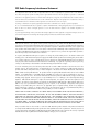
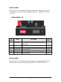
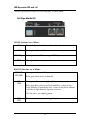
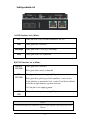
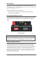
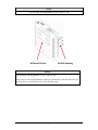
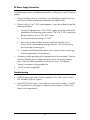
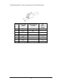
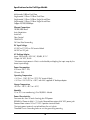
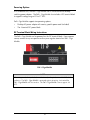
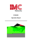
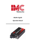
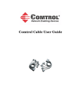
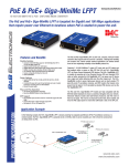
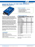
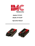
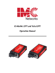
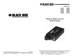
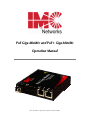
PoE Giga-MiniMc and PoE+ Giga-MiniMc
Operation Manual
Above illustration is representative; different models available.
FCC Radio Frequency Interference Statement
This equipment has been tested and found to comply with the limits for a Class A computing device, pursuant to Part 15 of the FCC Rules.
These limits are designed to provide reasonable protection against harmful interference when the equipment is operated in a commercial
environment. This equipment generates, uses and can radiate radio frequency energy and, if not installed and used in accordance with the
instruction manual, may cause harmful interference to radio communications. Operation of this equipment in a residential area is likely to
cause harmful interference in which the user will be required to correct the interference at his own expense.
Any changes or modifications not expressly approved by the manufacturer could void the user’s authority to operate the equipment.
The use of non-shielded I/O cables may not guarantee compliance with FCC RFI limits. This digital apparatus does not exceed the Class A
limits for radio noise emission from digital apparatus set out in the Radio Interference Regulation of the Canadian Department of
Communications.
Le présent appareil numérique n’émet pas de bruits radioélectriques dépassant les limites applicables aux appareils numériques de classe A
prescrites dans le Règlement sur le brouillage radioélectrique publié par le ministère des Communications du Canada.
Warranty
IMC Networks warrants to the original end-user purchaser that this product, EXCLUSIVE OF SOFTWARE, shall be free
from defects in materials and workmanship under normal and proper use in accordance with IMC Networks' instructions
and directions for a period of six (6) years after the original date of purchase. IMC Networks warrants to the original enduser purchaser that all SFPs shall be free from defects in materials and workmanship under normal and proper use in
accordance with IMC Networks' instructions and directions for a period of one (1) year after the original date of purchase.
This warranty is subject to the limitations set forth below.
At its option, IMC Networks will repair or replace at no charge the product which proves to be defective within such
warranty period. This limited warranty shall not apply if the IMC Networks product has been damaged by unreasonable
use, accident, negligence, service or modification by anyone other than an authorized IMC Networks Service Technician
or by any other causes unrelated to defective materials or workmanship. Any replaced or repaired products or parts carry
a ninety (90) day warranty or the remainder of the initial warranty period, whichever is longer.
To receive in-warranty service, the defective product must be received at IMC Networks no later than the end of the
warranty period. The product must be accompanied by proof of purchase, satisfactory to IMC Networks, denoting
product serial number and purchase date, a written description of the defect and a Return Merchandise Authorization
(RMA) number issued by IMC Networks. No products will be accepted by IMC Networks which do not have an RMA
number. For an RMA number, contact IMC Networks at PHONE: (800) 624-1070 (in the U.S and Canada) or (949) 4653000 or FAX: (949) 465-3020. The end-user shall return the defective product to IMC Networks, freight, customs and
handling charges prepaid. End-user agrees to accept all liability for loss of or damages to the returned product during
shipment. IMC Networks shall repair or replace the returned product, at its option, and return the repaired or new
product to the end-user, freight prepaid, via method to be determined by IMC Networks. IMC Networks shall not be
liable for any costs of procurement of substitute goods, loss of profits, or any incidental, consequential, and/or special
damages of any kind resulting from a breach of any applicable express or implied warranty, breach of any obligation
arising from breach of warranty, or otherwise with respect to the manufacture and sale of any IMC Networks product,
whether or not IMC Networks has been advised of the possibility of such loss or damage.
EXCEPT FOR THE EXPRESS WARRANTY SET FORTH ABOVE, IMC NETWORKS MAKES NO OTHER WARRANTIES,
WHETHER EXPRESS OR IMPLIED, WITH RESPECT TO THIS IMC NETWORKS PRODUCT, INCLUDING WITHOUT
LIMITATION ANY SOFTWARE ASSOCIATED OR INCLUDED. IMC NETWORKS SHALL DISREGARD AND NOT BE
BOUND BY ANY REPRESENTATIONS OR WARRANTIES MADE BY ANY OTHER PERSON, INCLUDING EMPLOYEES,
DISTRIBUTORS, RESELLERS OR DEALERS OF IMC NETWORKS, WHICH ARE INCONSISTENT WITH THE WARRANTY
SET FORTH ABOVE. ALL IMPLIED WARRANTIES INCLUDING THOSE OF MERCHANTABILITY AND FITNESS FOR A
PARTICULAR PURPOSE ARE HEREBY LIMITED TO THE DURATION OF THE EXPRESS WARRANTY STATED ABOVE.
Every reasonable effort has been made to ensure that IMC Networks product manuals and promotional materials
accurately describe IMC Networks product specifications and capabilities at the time of publication. However, because of
ongoing improvements and updating of IMC Networks products, IMC Networks cannot guarantee the accuracy of printed
materials after the date of publication and disclaims liability for changes, errors or omissions.
ii
Table of Contents
FCC Radio Frequency Interference Statement ....................................................ii
Warranty............................................................................................................ii
About the PoE Giga-MiniMc...............................................................................1
Installation .........................................................................................................1
DIP Switch Configuration SFP and 1x9 ...............................................................2
LED Operation SFP and 1x9...............................................................................4
Powering Option................................................................................................6
DIN Rail and Wallmount Bracket .......................................................................6
DC Power Supply Precautions............................................................................8
Troubleshooting .................................................................................................8
Specifications for the PoE Giga-MiniMc............................................................10
About the PoE+ Giga-MiniMc.........................................................................12
Installation .......................................................................................................12
DIP Switch Configuration SFP and 1x9 .............................................................13
LED Operation SFP and 1x9.............................................................................15
Powering Options ............................................................................................17
DIN Rail and Wallmount Bracket .....................................................................18
DC Power Supply Precautions..........................................................................19
Troubleshooting ...............................................................................................19
RJ-45 Pinouts ...................................................................................................20
Specifications for the PoE+ Giga-MiniMc........................................................21
PoE Precautions (For Inside-a-Building Installation ONLY) ................................22
IMC Networks Technical Support.....................................................................22
Fiber Optic Cleaning Guidelines.......................................................................23
Electrostatic Discharge Precautions...................................................................23
Safety Certifications..........................................................................................24
iii
About the PoE Giga-MiniMc
The PoE Giga-MiniMc is a solution for private network applications that require
power over Ethernet for locations inside buildings where PoE is required to power an
Ethernet device. The standalone unit offers a model with one SFP or fixed fiber
transceiver, 1x9, uplink for the network connection, one PSE 10/100/1000Base-T
copper port that provides Power-over-Ethernet (IEEE802.3af), and one
10/100/1000Mbps copper port. As a fiber-fed demarcation unit, it provides both
power and data to a remote device over a standard CAT5 copper line, eliminating the
need for a power connection to the remote device. The PoE Giga-MiniMc provisions
up to 15.4 watts on one copper port, and can be powered by an external AC adapter
or DC terminal block. For more robust power requirements on both copper ports,
please refer to the information about the PoE+ Giga-MiniMc on Page 13.
The SFP uplink can support fiber or copper SFPs. The fiber SFP, available in SC or LC
connectors, supports 100FDX or 1000FDX; a copper SFP supports the SGMII
interface (10/100/1000Mbps). The SFP, with or without DDMI, is available for
purchase through IMC Networks Distributors. The SFP must be MSA-compliant.
The copper ports auto negotiate to the connected device’s speed and duplex mode:
10 Mbps, 100 Mbps or 1000 Mbps, and HDX or FDX (including Flow Control). The
PoE Giga-MiniMc supports jumbo frames up to 10240.
NOTE
Unless noted otherwise, any reference is applicable for both the 1x9 and SFP version of
the PoE Giga-MiniMc in this manual.
Installation
PoE Giga-MiniMc installs virtually anywhere: as a standalone, table-top device, on a
DIN rail, or using a Wallmount bracket. As a standalone device, the end user can
install PoE Giga-MiniMc in locations with extremely limited space. Velcro strips are
also included to attach the device to most surfaces. The DIN Rail clips and
Wallmount bracket are optional, available for purchase through IMC networks
Distributors.
Installation Tip
Several models of the PoE Giga-MiniMc support single-strand fiber for operation. Since singlestrand fiber products use optics that transmit and receive on two different wavelengths, singlestrand fiber products must be deployed in pairs. For example, connect a PoE Giga-MiniMc ,
TX/SSLX-SM1310-SC (which has 1310 xmt and 1550 rcv) to a product which has 1550 xmt
and 1310 rcv, e.g. PoE Giga-MiniMc, TX/SSLX-SM1550-SC. The two connected products
must also have the same speed and distance capabilities (i.e. both are single-mode [20km] or
both are single/PLUS [40km]).
1
DIP Switch Configuration SFP and 1x9
PoE Giga-MiniMc SFP
DIP
Switch
1
2
3
4
5
6
Name
Description
PoE Reset
ON forces Port 2, PSE/PoE, to OFF on LOS of
Fiber input
Do not change
ON sets SFP for low speed operation
Do not change
Do not change
Do not change
Factory Set
LoSpd
Factory Set
Factory Set
Factory Set
Default
Setting
OFF
OFF
OFF
OFF
OFF
OFF
LoSPd DSW for PoE Giga-MiniMc
The DIP Switch for LoSPd is to allow the end user to set a speed for a fiber SFP under
the following conditions:
• Setting the LoSPd DSW to ON will force the SFP to operate at 100Mbps. When
set in the default of OFF, the SFP will run at it’s maximum rate of the SFP
installed.
• If a dual speed fiber SFP 100/1000Mbps is installed, setting the LoSpd to ON will
force the SFP to operate at 100Mbps.
NOTE
Under no conditions will the LoSPd DSW impact any copper SFPs. Some
1000Mbps SFPs may not function properly when forced to 100Mbps.
2
PoE Reset DSW
When set to ON, it will force the PSE output power on the copper port OFF when
the LINK state is lost on the SFP line (copper or fiber SFP). By default, the DSW is
set to OFF.
PoE Gig-MiniMc 1x9
DIP
Switch
1
2
3
4
5
6
Name
Description
PoE Reset
ON forces Port 2, PSE/PoE, to OFF on LOS of
Fiber input
Do not change
Do not change
Do not change
Do not change
Do not change
Factory Set
Factory Set
Factory Set
Factory Set
Factory Set
Default
Setting
OFF
OFF
OFF
OFF
OFF
OFF
PoE Reset DSW
When set to ON, it will force the PSE output power on the copper port OFF when
the LINK state is lost on the fiber segment. By default, the DSW is set to OFF.
3
LED Operation SFP and 1x9
The PoE Giga-MiniMc includes LEDs for three ports, as shown below:
PoE Giga-MiniMc SFP
SFP LED Functions are as follows:
FLT
Glows red when a fault has been detected on the unit
LNK
Glows green with a valid link
1000 Mbps
PWR
Glows green when SFP is running at 1000Mbps
Glows green when unit is powered
RJ-45 LED Functions are as follows:
LNK/ACT
(TX1, TX2)
PSE
(TX2)
Glows green with a valid link
Blinks green when activity is detected
Glows green when port is supplying PoE power
Blinks green during training and fault conditions: a series of two
flashes indicates an overcurrent fault; a series of five flashes indicates
invalid low or high discovery signature resistance
Off if the port is not supplying power
FDX
(TX1)
Glows amber when port is running full duplex
4
PoE Giga-MiniMc 1x9
1x9 LED Functions are as follows:
FLT
Glows red when a fault has been detected on the unit
LNK
Glows green with a valid link
1000 Mbps
PWR
Glows green when is running at 1000Mbps
Glows green when unit is powered
RJ-45 LED Functions are as follows:
LNK/ACT
(TX1, TX2)
Glows green with a valid link
PSE
(TX1, TX2)
Glows green when port is supplying PoE power
Blinks green when activity is detected
Blinks green during training and fault conditions: a series of two
flashes indicates an overcurrent fault; a series of five flashes indicates
invalid low or high discovery signature resistance
Off if the port is not supplying power
FDX
(TX1)
Glows amber when port is running full duplex
NOTE
The fixed twisted pair port labeled PSE is the only port capable of providing Power Over
Ethernet.
5
Powering Option
As a standalone unit, the PoE Giga-MiniMc uses a universal external desktop
switching power adapter. The PoE Giga-MiniMc also includes a DC terminal block to
support a voltage range of 45 to 57 VDC
PoE Giga-MiniMc supports two powering options.
•
•
Desktop AC power adapter with country specific power cord (included)
The 4-terminal DC power block
DC Terminal Block Wiring Instructions
The PoE Giga-MiniMc can be powered via the DC terminal block. From a power
source, connect to any one positive and any one negative terminal on PoE GigaMiniMc.
PoE Giga-MiniMc
NOTE
When using stranded wire, the leads must be tinned, and equivalent to a 16 AWG solid
conductor. The PoE Giga-MiniMc is protected against mis-wiring; if mis-wired the PoE
Giga-MiniMc will not function. The PoE Giga-MiniMc cannot support -48 VDC.
DIN Rail and Wallmount Bracket
The PoE Giga-MiniMc can be mounted with DIN Rail clips, a hardware option
available through IMC Networks. The DIN Rail clips include screws, to allow the
installation onto a DIN Rail. Install the screws into DIN Rail clips, which should be
mounted perpendicular to the DIN Rail. Snap the converter onto the clips. To
remove the converter from the DIN Rail, use a flat-head screwdriver into the slot to
gently pry the converter from the rail. In addition, a Wallmount bracket can be
installed onto the PoE Giga-MiniMc.
6
NOTE
The DIN clips are designed for use on a DIN-35 rail.
Wallmount Bracket
Din Rail Mounting
NOTE
The DIN clips are designed for use on a DIN-35 rail.
When using the side-installed location, remove the countersunk screw from the enclosure,
and then use the vacated hole for one of the DIN clip screws.
7
DC Power Supply Precautions
The following precautions should be observed when installing chassis with DC power
supplies.
1.
Check nameplate ratings to assure there is no overloading of supply circuits that
could have an effect on overcurrent protection and supply wiring.
2.
When installing 45 to 57 VDC rated equipment, it must be installed only per the
following conditions:
a.
Connect the equipment to a 45 to 57 VDC supply source that is electrically
isolated form the alternating current source. The 45 to 57 VDC source must
be connected to a 45 to 57 VDC SELV source.
b.
The maximum terminal voltage is 57 VDC.
c.
Input wiring to terminal block must be routed and secured in such a
manner that it is protected from damage and stress. Do not route wiring
past sharp edges or moving parts.
d.
A readily accessible disconnect device, with a 3mm minimum contact gap,
shall be incorporated in the fixed wiring.
3.
Grounding: reliable grounding of this equipment must be maintained. Particular
attention should be given to supply connections when connecting to power
strips, rather than direct connections to the branch circuit. The Negative
Terminal is common to the grounded case.
4.
-48 VDC cannot be supported.
Troubleshooting
•
PWR LED glows green when the unit is powered. If this LED is not lit, contact
IMC Networks Technical Support.
•
If the PSE LED flashes twice, it may indicate an over current condition. The PSE
LED should maintain solid green, to indicate consistent power. Check the PD
device and its requirements.
8
The following table lists the pin configuration for the RJ-48 connector.
Pin#
Signal Name
1000M
Signal Direction
10/100M
1
2
3
4
5
6
7
8
TXD1+
TXD1RXD2+
D3+
D3RXD2D4+
D4-
Out*
Out*
IN*
PoE
PoE+
(ALT-B)
+V
+V
In*
-V
-V
9
Specifications for the PoE Giga-MiniMc
Multi-mode 1300nm Dual Fiber
Single-mode 1310nm 1550nm Dual Fiber
Single-mode 1310nm 1490nm Single-Strand Fiber
Single-mode 1310nm 1550nm Single-Strand Fiber
Copper 10/100/1000Mbps
Ethernet Connections
10/100/1000 BaseT
Auto Negotiation
AutoCross
Flow Control
10240 MTU
Full Line-Rate Forwarding
DC Input Voltage
45 VDC to 57 VDC on DC terminal block
48 VDC on DC jack
AC Desktop Adapter
Input: 100 to 240 ±10% VAC, 50/60H, 0.7A *
Output: 48 VDC, 0.62A
* Maximum input power in Watts is calculated by multiplying the input amps by the
lowest input voltage.
Power Consumption
21W max (PSE + PD)
5W max (PSE)
Operating Temperature
+32°F to + 158°F (0°C to +70°C) DC terminal block
+32°F to +122°F (0°C to +50°C) with IMC supplied AC desktop adapter
Storage Temperature
-40°F to +185°F (-40°C to +85°C)
Humidity
5% to 95% (non-condensing); 0 to 10,000 ft. altitude
Power Characteristics
Consumes less than 10 watts (heating) plus PSE power
IEEE802.3af Power to field < 15.4 watts Powered from external 48 VDC power jack
Powered from external 45 to 57 VDC 4-position terminal block
The input power terminals are isolated from the unit chassis
Threaded Chassis Grounding holes on unit for ground lug mounting
10
Standards Compliance
IEEE 802.3af Power Over Ethernet
IEEE 802.3 Ethernet Standards
IEEE 802.3u Auto-Negotiation
RFC-2474
RFC-2475 DiffServ QoS
IMC Networks Products
SFPs
PoE Giga-MiniMc
Length of Warranty
1 year
6 year
NOTE
Please refer to the Warranty Section at the beginning of this manual for the full
terms of the warranty.
11
About the PoE+ Giga-MiniMc
The PoE+ Giga-MiniMc is a solution for private network applications that require
power over Ethernet for locations inside buildings where PoE is required to power an
Ethernet device. The standalone unit offers a model with one SFP or fixed fiber
transceiver, 1x9, uplink for the network connection, and two PSE 10/100/1000Base-T
copper ports that provides Power-over-Ethernet (IEEE802.3af). As a fiber-fed
demarcation unit, it provides both power and data to a remote device over a
standard CAT5 copper line, eliminating the need for a power connection to the
remote device. The PoE+ Giga-MiniMc provides up to 25.4 watts per copper port
and is powered by an external AC adapter or DC terminal block.
The SFP uplink can support fiber or copper SFPs. The fiber SFP, available in SC or LC
connectors, supports 100FDX or 1000FDX; a copper SFP supports the SGMII
interface (10/100/1000Mbps). The SFP, with or without DDMI, is available for
purchase through IMC Networks Distributors. The SFP must be MSA-compliant.
The copper ports auto negotiate to the connected device’s speed and duplex mode:
10 Mbps, 100 Mbps or 1000 Mbps, and HDX or FDX (including Flow Control). The
PoE+ Giga-MiniMc supports jumbo frames up to 10240.
NOTE
Unless noted otherwise, any reference is applicable for both the 1x9 and SFP version of
the PoE+ Giga-MiniMc in this manual.
Installation
PoE+ Giga-MiniMc installs virtually anywhere: as a standalone, table-top device, on a
DIN rail or using a Wallmount bracket. As a standalone device, the end user can
install PoE+ Giga-MiniMc in locations with extremely limited space. Velcro strips are
also included to attach the device to most surfaces. The DIN Rail clips and
Wallmount bracket are optional, available for purchase through an IMC Networks
Distributor.
Installation Tip
Several models of the PoE+ Giga-MiniMc support single-strand fiber for operation. Since
single-strand fiber products use optics that transmit and receive on two different wavelengths,
single-strand fiber products must be deployed in pairs. For example, connect a PoE+ GigaMiniMc, TX/SSLX-SM1310-SC (which has 1310 xmt and 1550 rcv) to a product which has
1550 xmt and 1310 rcv, e.g. PoE+ Giga-MiniMc, TX/SSLX-SM1550-SC. The two connected
products must also have the same speed and distance capabilities (i.e. both are single-mode
[20km] or both are single/PLUS [40km]).
12
DIP Switch Configuration SFP and 1x9
PoE+ Giga-MiniMc SFP
DIP
Switch
1
Name
PoE Reset 2
2
PoE Reset 1
3
4
5
6
LoSpd
Factory Set
Factory Set
Factory Set
Definition
Default
Setting
ON forces Port 2 PoE OFF on LOS of Fiber
input
ON forces Port 1 PoE OFF on LOS of Fiber
input
ON sets SFP for low speed operation
Do not change
Do not change
Do not change
OFF
OFF
OFF
OFF
OFF
OFF
LoSPd DSW for PoE+ Giga-MiniMc
The DIP Switch for LoSPd is to allow the end user to set a speed for a fiber SFP under
the following conditions:
• Setting the LoSPd DSW to ON will force the SFP to operate at 100Mbps. When
set in the default of OFF, the SFP will run at it’s maximum rate of the SFP
installed.
• If a dual speed fiber SFP 100/1000Mbps is installed, setting the LoSpd to ON will
force the SFP to operate at 100Mbps
NOTE
Under no conditions will the LoSPd DSW impact any copper SFPs. Some
1000Mbps SFPs may not function properly when forced to 100Mbps.
PoE Reset 1 and PoE Reset 2 DSW
When set to ON, it will force the PSE output power on the copper port OFF when
the LINK state is lost on the fiber segment. By default, the DSW is set to OFF.
13
PoE+ Giga-MiniMc 1x9
DIP
Switch
1
2
3
4
5
6
Name
PoE Reset 2
PoE Reset 1
Factory Set
Factory Set
Factory Set
Factory Set
Description
ON forces Port 2 PoE OFF on LOS of Fiber
input
ON forces Port 1 PoE OFF on LOS of Fiber
input
Do not change
Do not change
Do not change
Do not change
Default
Setting
OFF
OFF
OFF
OFF
OFF
OFF
PoE Reset 1 and PoE Reset 2 DSW
When set to ON, it will force the PSE output power on the copper port OFF when
the LINK state is lost on the fiber segment. By default, the DSW is set to OFF.
14
LED Operation SFP and 1x9
The PoE+ Giga-MiniMc includes LEDs for three ports, as shown below:
PoE+ Giga-MiniMc SFP
SFP LED Functions are as follows:
FLT
Glows red when a fault has been detected on the unit
LNK
Glows green with a valid link
1000 Mbps
PWR
Glows green when SFP is running at 1000Mbps
Glows green when unit is powered
RJ-45 LED Functions are as follows:
LNK/ACT
(TX1, TX2)
Glows green with a valid link
PSE
(TX1, TX2)
Glows green when port is supplying PoE power
Blinks green when activity is detected
Blinks green during training and fault conditions: a series of two
flashes indicates an overcurrent fault; a series of five flashes
indicates invalid low or high discovery signature resistance.
Off if the port is not supplying power
15
PoE+ Giga-MiniMc 1x9
1x9 LED Functions are as follows:
FLT
Glows red when a fault has been detected on the unit
LNK
Glows green with a valid link
1000 Mbps
PWR
Glows green to indicate is running at 1000Mbps
Glows green when unit is powered
RJ-45 LED Functions are as follows:
LNK/ACT
(TX1, TX2)
Glows green with a valid link
PSE
(TX1, TX2)
Glows green when port is supplying PoE power
Blinks green when activity is detected
Blinks green during training and fault conditions: a series of two
flashes indicates an overcurrent fault; a series of five flashes indicates
invalid low or high discovery signature resistance.
Off if the port is not supplying power
16
Powering Options
As a standalone unit, the PoE+ Giga-MiniMc uses a universal external desktop
switching power adapter. The PoE+ Giga-MiniMc also includes a DC terminal block
to support a voltage range of 51 to 57 VDC.
PoE+ Giga-MiniMc supports two powering options.
•
•
Desktop AC power adapter with country specific power cord (included)
The 4-terminal DC power block
DC Terminal Block Wiring Instructions
The PoE+ Giga-MiniMc can be powered via the DC terminal block. From a power
source, connect to any one positive and any one negative terminal on PoE+ GigaMiniMc.
PoE+ Giga-MiniMc
NOTE
When using stranded wire, the leads must be tinned, and equivalent to a 16 AWG solid
conductor. The PoE+ Giga-MiniMc is protected against mis-wiring; if mis-wired the
PoE+ Giga-MiniMc will not function. The PoE+ Giga-MiniMc cannot support -48
VDC.
17
DIN Rail and Wallmount Bracket
The PoE+ Giga-MiniMc can be mounted with two DIN Rail clips, a hardware option
available through IMC Networks. The DIN Rail clips include screws, to allow the
installation onto a DIN Rail. Install the screws into DIN Rail clips, which should be
mounted perpendicular to the DIN Rail. Snap the converter onto the clips. To
remove the converter from the DIN Rail, use a flat-head screwdriver into the slot to
gently pry the converter from the rail. In addition, a Wallmount bracket can be
installed onto the PoE+ Giga-MiniMc (optional purchase).
Wallmount Bracket
Din Rail Mounting
NOTE
The DIN clips are designed for use on a DIN-35 rail.
18
DC Power Supply Precautions
The following precautions should be observed when installing chassis with DC power
supplies.
1.
Check nameplate ratings to assure there is no overloading of supply circuits that
could have an effect on overcurrent protection and supply wiring.
2.
When installing 51 to 57 VDC rated equipment, it must be installed only per the
following conditions:
a.
Connect the equipment to a 51 to 57 VDC supply source that is electrically
isolated form the alternating current source. The 51 to 57 VDC source must
be connected to a 51 to 57 VDC SELV source.
b.
The maximum terminal voltage is 57 VDC.
c.
Input wiring to terminal block must be routed and secured in such a
manner that it is protected from damage and stress. Do not route wiring
past sharp edges or moving parts.
d.
A readily accessible disconnect device, with a 3mm minimum contact gap,
shall be incorporated in the fixed wiring.
3.
Grounding: reliable grounding of this equipment must be maintained. Particular
attention should be given to supply connections when connecting to power
strips, rather than direct connections to the branch circuit. The Negative
Terminal is common to the grounded case.
4.
-48 VDC cannot be supported.
Troubleshooting
If the PoE+ Giga-MiniMc is not responding to the power provided to it, the following
conditions may be responsible:
• There may be an overcurrent condition; this is indicated on the PSE LED by a
series of two flashes.
• There may be an invalid low or high discovery signature resistance; this is
indicated on the PSE LED by a series of five flashes.
• If the PoE injector has power that can be verified, but the PSE LED is off, then
contact IMC Networks technical support.
19
RJ-45 Pinouts
The following table lists the pin configuration for the RJ-48 connector.
Pin#
Signal Name
1000M
Signal Direction
10/100M
1
2
3
4
5
6
7
8
TXD1+
TXD1RXD2+
D3+
D3RXD2D4+
D4-
Out*
Out*
IN*
PoE
PoE+
(ALT-B)
+V
+V
In*
-V
-V
20
Pin#
1
2
3
4
5
6
7
8
Specifications for the PoE+ Giga-MiniMc
Multi-mode 1300nm Dual Fiber
Single-mode 1310nm 1550nm Dual Fiber
Single-mode 1310nm 1490nm Single-Strand Fiber
Single-mode 1310nm 1550nm Single-Strand Fiber
Copper 10/100/1000Mbps
Ethernet Connections
10/100/1000 BaseT
Auto Negotiation
AutoCross
Flow Control
10240 MTU
Full Line-Rate Forwarding
DC Input Voltage
51 to 57 VDC on DC terminal block
51 to 57 VDC on DC jack
AC Desktop Adapter
Input: 100 to 240 ±10% VAC, 50/60H, 2A *
Output: 52 VDC, 2.31A
* Maximum input power in Watts is calculated by multiplying the input amps by the
lowest input voltage.
Power Consumption
65W max (PSE + PD)
5W max (PSE)
Operating Temperature
+32°F to +158°F (0°C to +70°C) DC terminal block
+32°F to +122°F (0°C to +50°C) with IMC supplied AC desktop adapter
Storage Temperature
-40°F to +185°F (-40°C to +85°C)
Humidity
5% to 95% (non-condensing); 0 to 10,000 ft. altitude
Power Characteristics
Consumes less than 10 watts (heating) plus PSE power
IEEE802.3af/at Power to field < 50 watts (2 x 25.4 watts)
Powered from external 51 to 57 VDC power jack
Powered from external 51 to 57 VDC 4-position terminal block
The input power terminals are isolated from the unit chassis
Threaded Chassis Grounding holes on unit for ground lug mounting
21
Standards Compliance
IEEE 802.3af Power Over Ethernet
IEEE 802.3at PoE+ Standards
IEEE 802.3 Ethernet Standards
IEEE 802.3u Auto-Negotiation
RFC-2474
RFC-2475 DiffServ QoS
IMC Networks Products
SFPs
PoE+ Giga-MiniMc
Length of Warranty
1 year
6 year
NOTE
Please refer to the Warranty Section at the beginning of this manual for the full
terms of the warranty.
PoE Precautions (For Inside-a-Building Installation ONLY)
The PoE Giga-MiniMc and PoE+ Giga-MiniMc are for inside-a-building
installation only. Both devices cannot be installed outside-a-building environment,
as they cannot meet the PoE requirements, per the PoE standard. If installing the
device outside, serious damage can occur and void the IMC Networks’ warranty.
IMC Networks Technical Support
Tel: (949) 465-3000 or (800) 624-1070 (in the U.S. and Canada);
+32-16-550880 (Europe)
Fax: (949) 465-3020
E-Mail: [email protected]
Web: www.imcnetworks.com
22
Fiber Optic Cleaning Guidelines
Fiber Optic transmitters and receivers are extremely susceptible to contamination by
particles of dirt or dust, which can obstruct the optic path and cause performance
degradation. Good system performance requires clean optics and connector ferrules.
1.
2.
3.
4.
Use fiber patch cords (or connectors, if you terminate your own fiber) only from
a reputable supplier; low-quality components can cause many hard-to-diagnose
problems in an installation.
Dust caps are installed at IMC Networks to ensure factory-clean optical devices.
These protective caps should not be removed until the moment of connecting
the fiber cable to the device. Should it be necessary to disconnect the fiber
device, reinstall the protective dust caps.
Store spare caps in a dust-free environment such as a sealed plastic bag or box
so that when reinstalled they do not introduce any contamination to the optics.
If you suspect that the optics have been contaminated, alternate between
blasting with clean, dry, compressed air and flushing with methanol to remove
particles of dirt.
Electrostatic Discharge Precautions
Electrostatic discharge (ESD) can cause damage to any product, add-in modules or
stand alone units, containing electronic components. Always observe the following
precautions when installing or handling these kinds of products
1.
Do not remove unit from its protective packaging until ready to install.
2.
Wear an ESD wrist grounding strap before handling any module or component.
If the wrist strap is not available, maintain grounded contact with the system unit
throughout any procedure requiring ESD protection.
3.
Hold the units by the edges; do not touch the electronic components or gold
connectors.
4.
After removal, always place the boards on a grounded, static-free surface, ESD
pad or in a proper ESD bag. Do not slide the modules or stand alone units over
any surface.
WARNING! Integrated circuits and fiber optic components are
extremely susceptible to electrostatic discharge damage. Do not
handle these components directly unless you are a qualified service
technician and use tools and techniques that conform to accepted
industry practices.
23
Safety Certifications
UL/CUL: Listed to Safety of Information Technology Equipment, including
Electrical Business Equipment.
CE: The products described herein comply with the Council Directive on
Electromagnetic Compatibility (2004/108/EC) and the Council
Directive on Electrical Equipment Designed for use within Certain
Voltage Limits (2006/95/EC). Certified to Safety of Information
Technology Equipment, Including Electrical Business Equipment. For
further details, contact IMC Networks.
Class 1 Laser product, Luokan 1 Laserlaite,
Laser Klasse 1, Appareil A’Laser de Classe 1
European Directive 2002/96/EC (WEEE) requires that any equipment that bears this
symbol on product or packaging must not be disposed of with unsorted municipal
waste. This symbol indicates that the equipment should be disposed of separately
from regular household waste. It is the consumer’s responsibility to dispose of this
and all equipment so marked through designated collection facilities appointed by
government or local authorities. Following these steps through proper disposal and
recycling will help prevent potential negative consequences to the environment and
human health. For more detailed information about proper disposal, please contact
local authorities, waste disposal services, or the point of purchase for this equipment.
24
19772 Pauling • Foothill Ranch, CA 92610-2611 USA
TEL: (949) 465-3000 • FAX: (949) 465-3020
www.imcnetworks.com
© 2011 IMC Networks. All rights reserved.
The information in this document is subject to change without notice. IMC Networks assumes no responsibility for any
errors that may appear in this document. PoE Giga-MiniMc and PoE+ Giga-MiniMc is a trademark of IMC Networks.
Other brands or product names may be trademarks and are the property of their respective companies.
Document Number 57-80912-00 A1
October 2011