1
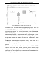
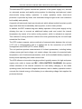
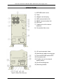
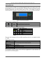
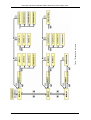
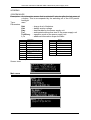
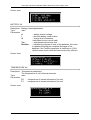
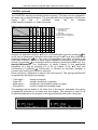
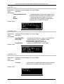
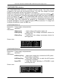
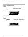
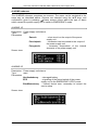
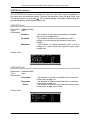
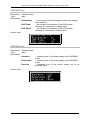
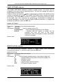
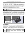
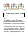
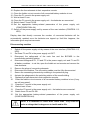
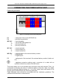
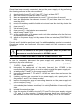
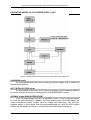
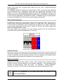
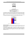
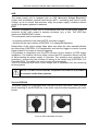
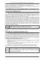
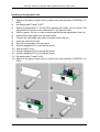
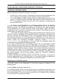
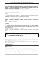
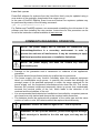
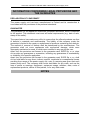
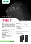
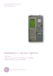
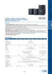
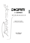
Instruction manual for SINLINE PRO 10000 series power supply units
TABLE OF CONTENTS
TABLE OF CONTENTS........................................................................................................................................ 2
INTRODUCTION .................................................................................................................................................. 3
GENERAL INFORMATION ................................................................................................................................. 3
INTENDED APPLICATION............................................................................................................................. 3
GENERAL DESCRIPTION .............................................................................................................................. 4
STRUCTURE ......................................................................................................................................................... 7
USER INTERFACE........................................................................................................................................... 8
SCREENS ........................................................................................................................................................ 10
Main menu ............................................................................................................................................................ 10
MEASUREMENTS submenu............................................................................................................................... 11
CONTROL submenu ............................................................................................................................................ 13
CONFIGURATION submenu .............................................................................................................................. 15
ALARMS submenu............................................................................................................................................... 17
STATISTICS submenu ......................................................................................................................................... 18
PANEL SETTINGS submenu............................................................................................................................... 20
IDENTIFICATION submenu ............................................................................................................................... 20
INDUSTRIAL WORK SAFETY INSTRUCTIONS............................................................................................ 21
TRANSPORT .................................................................................................................................................. 21
ELECTRICAL SAFETY ................................................................................................................................. 21
INSTALLATION.................................................................................................................................................. 22
UNPACKING .................................................................................................................................................. 22
INSTALLATION OF THE POWER SUPPLY UNIT..................................................................................... 23
BATTERY MODULE ..................................................................................................................................... 23
Connecting modules.............................................................................................................................................. 24
Disconnecting modules ......................................................................................................................................... 25
CONNECTING THE POWER SUPPLY UNIT................................................................................................... 26
Connecting elements ............................................................................................................................................. 26
Electrical system ................................................................................................................................................... 27
START-UP....................................................................................................................................................... 27
SWITCHING OFF AND DISCONNECTING THE POWER SUPPLY UNIT .............................................. 28
OPERATING MODES OF THE POWER SUPPLY UNIT ............................................................................ 29
OTHER FUNCTIONAL ELEMENTS ............................................................................................................ 30
PROTECTION...................................................................................................................................................... 30
AVR ................................................................................................................................................................. 33
EPO .................................................................................................................................................................. 33
Service BYPASS.............................................................................................................................................. 33
COOPERATION OF THE POWER SUPPLY UNIT WITH A PC ..................................................................... 34
RS232 AND USB COMMUNICATION......................................................................................................... 34
EVER SNMP/HTTP NETWORK MANAGEMENT CARD .......................................................................... 34
Installing a management card................................................................................................................................ 35
INSTALLING AND CONFIGURING POWERSOFT PERSONAL .............................................................. 36
Installing on a Windows system ........................................................................................................................... 36
Installing on a Linux/Unix system ........................................................................................................................ 36
Updating software ................................................................................................................................................. 37
COMMENTS REGARDING OPERATION ........................................................................................................ 38
COOPERATION OF THE POWER SUPPLY UNIT WITH ELECTRICITY GENERATORS..................... 39
STORAGE, MAINTENANCE AND TRANSPORT....................................................................................... 39
RECYCLING ................................................................................................................................................... 39
TECHNICAL PARAMETERS............................................................................................................................. 40
INSTALLATION GUIDELINES .................................................................................................................... 40
TECHNICAL DATA............................................................................................................................................ 41
INFORMATION CONCERNING LEGAL PROVISIONS AND THE GUARANTEE...................................... 42
DECLARATION OF CONFORMITY ............................................................................................................ 42
GUARANTEE ................................................................................................................................................. 42
NOTES.................................................................................................................................................................. 42
2010/08/24
www.ever.eu
2
Instruction manual for SINLINE PRO 10000 series power supply units
INTRODUCTION
Thank you for purchasing the EVER SINLINE PRO 10000 power supply unit. It
belongs to a series of technologically advanced power supply units intended for
servers, computer networks and data processing systems.
The UPS EVER SINLINE PRO 10000 has been designed in such a way as to best
meet all your expectations regarding protection against the consequences of power
outages.
The present instruction manual contains information on operating the device and sets
forward the principles of safe usage. Please read the instruction manual thoroughly
before operating the EVER SINLINE PRO 10000 power supply unit, for this will
surely facilitate correct and trouble-free usage. The power supply unit has been
manufactured in Poland, in full accordance with requirements introduced for the CE
symbol.
GENERAL INFORMATION
INTENDED APPLICATION
Power supply unit of the SINLINE PRO 10000 series are class LINE-INTERACTIVE
(VI) devices, intended for cooperation with equipment powered from a single-phase
~230 V power grid.
NOTE! SINLINE PRO 10000 power supply units are not intended
for usage with medical life and/or health support systems.
2010/08/24
www.ever.eu
3
Instruction manual for SINLINE PRO 10000 series power supply units
GENERAL DESCRIPTION
•
Sinusoidal output voltage, generated in battery operation mode;
•
DPC (Digital Power Control) - Digital control of the power supply units
operating parameters, such as:
- output voltage shape,
- output voltage frequency,
- battery charge status,
- battery voltage and current,
- measurement of the capacity of a set of batteries,
- life of batteries,
- temperature of critical elements of the power supply unit;
•
Digital measurement of external parameters, such as:
- mains voltage value,
- mains current value,
- mains voltage frequency,
- value of active and apparent power received from the mains,
- coefficient of mains-side power,
- value of active and apparent power connected to the power supply unit's
output,
- coefficient of output-side power,
•
An automatic voltage regulation system (AVR), which increases and decreases;
•
Mains voltage filtration;
•
RS232 and USB serial ports for communication with a PC;
•
Socket for adapter cards (e.g. a management card);
•
Possibility of connecting additional battery packs;
•
Possibility of browsing network event statistics;
•
Calculating the current available emergency operation time;
•
PowerSoft Personal software is used to control the power supply unit and
automatically close the system;
2010/08/24
www.ever.eu
4
Instruction manual for SINLINE PRO 10000 series power supply units
Figure 1: Simplified block diagram of the power supply unit
The SINLINE PRO 10000 power supply unit is a modern electronic device that
serves as an autonomous source of sinusoidal 230 V voltage. The device belongs to
the LINE–INTERACTIVE (VI) class of UPSs, which includes power supply units that
synchronize with the power grid. The unit is equipped with the unique CLEAR
DIGITAL SINUS (CDS) system that during battery operation generates a precisely
stabilised output voltage with a sinusoidal shape, which makes it possible to power
a broad range of loads that do not tolerate quasi-sinusoidal voltages. The application
of this system increases the reliability of the device, guaranteeing its stable
operation.
The Automatic Voltage Regulation (AVR) system allows the power supply unit to
immediately correct even small drops and rises in mains voltage, so as to ensure that
receivers enjoy the proper supply conditions without using up the power gathered in
batteries.
What is more, the unit has been fitted with an advanced DIGITAL POWER
CONTROL (DPC) system, which precisely shapes the course of the unit's output
voltage so as to generate a purely sinusoidal voltage. During mains operation, the
system filters the mains voltage in order to eliminate interferences and distortions
that could be potentially harmful to receivers.
2010/08/24
www.ever.eu
5
Instruction manual for SINLINE PRO 10000 series power supply units
The dedicated DPC system controls the operation of the power supply unit, and has
an extremely precise and rapidly acting system for detecting overloads and output
short-circuits during battery operation. In mains operation mode, short-circuit
protection is provided by fuses, with overloads being brought to the user's attention
both audibly and optically.
A special soft start mode has been introduced, which allows trouble-free start-up with
large loads that draw considerably start-up power, such as laser printers.
In addition, the DPC enables long-term battery operation of the power supply unit by
allowing the user to connect an additional battery pack and control the internal
temperature by means of an active cooling system, which is activated as required.
This method of cooling activation reduces the noise generated by the unit and helps
extend the life of fans.
The DPC system supports various methods of communication between the unit and
a PC over a communication link or a special link for the connection of an EVER
management card EVER (HTTP, telnet, SNMP).
The unit performs precise measurements of its basic parameters, including battery
voltage, power grid input voltage, unit output voltage, the power of connected loads,
temperature, and of advanced parameters, such as the available battery capacity or
backup mode operating time under current load.
The UPS utilises an innovative charging method, typically reserve for high-end power
supply units. which is known as CBC - COOL BATTERY CHARGING; this system
utilises elements of the internal converter for cold battery charging. In the mains
operating mode, this function charges the batteries, while in battery operation mode it
converts the internal energy of the battery to an alternating voltage that supplies the
protected devices.
2010/08/24
www.ever.eu
6
Instruction manual for SINLINE PRO 10000 series power supply units
STRUCTURE
1) BYPASS switch cover
2) Fans
3) Adapter card slot plug
4) USB communication link
5) RS232 communication link
6) EPO link
7) Fusible cut-out for internal
batteries
8) Connection links cover
9) AC input automatic fuses
10) Mechanical cable mounting grip
11) Service BYPASS switch/UPS
12) Connection link
13) Fusible cut-out for external
battery packs
14) Device earthing point
15) Mounting holders
Figure 2: Views of the rear panel
2010/08/24
www.ever.eu
7
Instruction manual for SINLINE PRO 10000 series power supply units
USER INTERFACE
The user interface consists of a four-button keypad located on the upper cover of the
power supply unit, an LCD, and three LEDs. They allow the user to monitor the unit's
operating parameters, and also modify some of them. The method of using the
interface and the meanings of individual parameters have been described hereunder.
Figure 3: View of the user interface
Table 1 Meanings of signalling diodes
Graphical symbol
Designation
LED 1
AVR
Description
LED indicating the unit's operation mode: NORMAL/BACKUP
LED 2
LED signalling activation of the AVR system
LED 3
LED signalling activation of the EMERGENCY mode
Table 2 Optical (diode) signalling
LED 1
LED 2 LED 3 Operation mode
UNKNOWN
F
NORMAL
BACKUP
STANDBY
READINESS
*
EMERGENCY
INIT
STOP
F - the status may be configuration-dependent (none or red);
* - flashes
The unit is also equipped with an audible signalling system for its respective states
(cf. table).
Table 3 Audible signalling
Action
NORMAL mode
BACKUP mode
Forced switch to the
STANDBY mode
EMERGENCY mode
Overload
Short circuit
Overheat
EPO activation
Audible signalling
None
intermittent signal, rapidity dependent on the charge level of batteries
(the more rapid the signal, the lower the battery charge level)
intermittent signal - two successive short signals followed by a pause
Event dependent
continuous signal
rapid intermittent 50% / 50% signal
slow intermittent 50% / 50% signal
intermittent sound/silence (1s / 5s) signal
All successive screens shown on the LCD are organised in a tree structure, as
presented in the following figure.
2010/08/24
www.ever.eu
8
Figure 1: Organisation of screens
Instruction manual for SINLINE PRO 10000 series power supply units
2010/08/24
www.ever.eu
9
Instruction manual for SINLINE PRO 10000 series power supply units
SCREENS
SCREENSAVER
Description: An information screen that is activated 5 minutes after the last press of
a button. This is accompanied by the switching off of the LCD panel's
backlight.
Type:
read
Parameters
Qak
– charge level of batteries
Uak
– battery section voltage
Owy
– load handled by the power supply unit
Tau
– anticipated autonomous time of the power supply unit
TrybPracy – operation mode of the power supply unit
i:, a:
– additional information as per the table
Information
Alarms
Abbreviation
Meaning
Abbreviation
L
Charging
ZW
Short circuit
Meaning
C
Overload
Overload
PC
G
Overheat
PG
Overheat
O
Waiting following STANDBY
AU
Damaged battery
N
90 sec. of autonomous time
remaining
EPO
EPO
S
Service
BW
Internal error
AP
AVR - increasing voltage
AO
AVR - decreasing voltage
e.g. a:PC
e.g. i:S
Screen view:
Main menu
2010/08/24
www.ever.eu
10
Instruction manual for SINLINE PRO 10000 series power supply units
The main menu comprises tree screens. Switching between screens is effected by
means of the ▼▲ keys. A selection is confirmed by pressing the
key, whereafter
a submenu may be selected in the chosen menu also by means of the ▼▲ keys.
The arrow on the left of the submenu name indicates the current position. Selections
are confirmed by the
key. To proceed to a higher level, press the ESC key.
MEASUREMENTS submenu
The MEASUREMENTS submenu is divided into four topical groups: INPUT,
OUTPUT, BATTERY, TEMPERATURE.
INPUT 1/4
Description:
Type:
Parameters
Power supply unit input parameters
read
U
I
f
PF
P
S
– input voltage of the power supply unit
– input current of the power supply unit
–input frequency of the power supply unit
– input coefficient of the power supply unit
– input active power of the power supply unit
– input apparent power of the power supply unit
Screen view:
OUTPUT 2/4
Description:
Type:
Parameters
Power supply unit output parameters
read
U
I
f
PF
P
S
2010/08/24
– output voltage of the power supply unit
– output current of the power supply unit
–output frequency
– output power coefficient
– output active power
– output apparent power
www.ever.eu
11
Instruction manual for SINLINE PRO 10000 series power supply units
Screen view:
BATTERY 3/4
Description: Battery-related parameters
Type:
read
Parameters
U
– battery section voltage
I
– absolute battery current value
Q
– charge level of batteries
(calculated for the current load)
Tau
– anticipated autonomous time
StanAku.
– indicates the degree of wear of the batteries; this value
is updated following the complete discharge of the
batteries if the TestAku parameter is switched on; 100%
(default value) means that the batteries are fully efficient
Screen view:
TEMPERATURE 4/4
Description: Temperature parameters
The temperature of unit's internal elements.
Type:
read
Parameters
T0
– temperature of internal elements of the unit
T1
– temperature of internal elements of the unit
Screen view:
2010/08/24
www.ever.eu
12
Instruction manual for SINLINE PRO 10000 series power supply units
CONTROL submenu
The CONTROL submenu is divided into three groups. The menu can be navigated in
the same way as described above. The user may alter the configuration of the power
supply
unit
only
if
individual
items
can
be
changed
under specific conditions. Cf. table hereunder.
BACKUP
X
Buzzer
X
Czas.Wyl.EPO
X
□
□
●
○
□
□
UPS->STB/STB->UPS
X
X
X
●
○
□
□
●
KasujAwarie
X
X
X
TestAku
X
□
□
●
●
□
□
●
■
□
□
X
X
EMERGENCY
NORMAL
(MAINS)
●
X
READINESS
INIT
X
UPS
Control flag
AwaryjneWylaczenie
STOP
UNKNOWN
Operation mode
STANDBY
Table. 4 Table of control flag changes
● X
○ X
□ □
□ □
X
X – change not allowed
● – only switch on
○ – only switch off
□ - switching
■ – only switch on; switch off
possible only when waiting for a
minimal load
X
X X
X X ●
□ □ □ □ □
Screens are selected using the ▲▼ keys, and confirmation given by pressing . As
in the case of parameters, selections are made using the ▲▼ keys and confirmation
given by pressing the
key. Two types of parameters have been included in the
CONTROL submenu. Some of them require repeated confirmation of an intended
change (by pressing ) or resignation without changing (pressing the ESC key), e.g.
AwaryjneWylaczenie. The modification of others consists in the appropriate
placement of a flag by selecting On or Off by means of the ▲▼ keys and
confirmation by pressing
. Confirmation is followed by automatic passage to
a screen one level higher in the tree structure.
Once confirmed, a parameter is save in the unit's memory. The saving process itself
is signalled by the following messages:
-- Trwa zapis --- Zapis OK --- Blad zapisu --- Zla wartość --
- saving in progress
- saving successfully completed
- saving was unsuccessful, please try again
- a value outside the permitted range
The message appear briefly in the lower line of the screen, whereafter the system
automatically proceeds to a screen one level higher. This principle is used for all
modifiable parameters. An example of saving screens has been given hereunder.
2010/08/24
www.ever.eu
13
Instruction manual for SINLINE PRO 10000 series power supply units
CONTROL 1/3
Description: Settings of power supply unit control flags.
Type:
read/save
Parameters
AwaryjneWylaczenie
– forced passage of the power supply unit to
the EPO mode from the user interface level
UPS
– switching the power supply unit on/off
Buzzer
– switching on/off of battery charge status
signalling for the BACKUP mode
Screen view:
CONTROL 2/4
Description: Settings of power supply unit control flags.
Type:
read/save
Parameters
Czas.Wyl.EPO
– temporary deactivation (1 min.) of the EPO link.
UPS->STB
– manual forcing of the STANDBY mode;
switching after a specified time
(CONFIGURATION 2/4; Opoz.STB)
KasujAwarie
– deletion of EMERGENCY mode flags
Screen view:
CONTROL 3/3
Description: Settings of power supply unit control flags.
Type:
read/save
Parameters
Test Aku
– permission to update the battery status indicator
following the complete discharge of batteries
Screen view:
2010/08/24
www.ever.eu
14
Instruction manual for SINLINE PRO 10000 series power supply units
CONFIGURATION submenu
The CONFIGURATION submenu is divided into four groups. The menu can be
navigated in the same way as described above. The user may change the power
supply unit parameter values if the keypad is not locked.
Screens are selected using the ▲▼ keys, and confirmation given by pressing . As
in the case of parameters, selections are made using the ▲▼ keys and confirmation
given by pressing the
key. The CONFIGURATION submenu contains numerical
parameters. Their modification consists in increasing or decreasing values by means
of the ▲▼ keys, and confirming by pressing
. Confirmation is followed by
automatic passage to a screen one level higher in the tree structure. To resign from
modifying a parameter, press the ESC key.
CONFIGURATION 1/4
Description: Power supply unit parameters
Type:
read/save
Parameters
UWyjsciowe
– output voltage of the power supply unit
UGornyProg
– upper limit of the voltage correctness criterion for
the supply line
UDolnyProg
– lower limit of the voltage correctness criterion for
the supply line
Screen view:
CONFIGURATION 2/4
Description: Power supply unit parameters
Type:
read/save
Parameters
AVRGornyProg – upper input voltage limit, at which the AVR system
(decreasing) is activated
AVRDolnyProg – lower input voltage limit, at which the AVR system
(increasing) is activated
Opoz.STB
– delay time when switching to STANDBY mode
forced by the user
Screen view:
2010/08/24
www.ever.eu
15
Instruction manual for SINLINE PRO 10000 series power supply units
CONFIGURATION 3/4
Description: Power supply unit parameters
Type:
read/save
Parameters
Poj. z STB.
– minimal charge level that the batteries
must attain in order for the power supply unit
to start up following a discharge
ProgKas.Prz.
– load level at which the power supply unit
ceases to signal an overload
Screen view:
CONFIGURATION 4/4
Description: Power supply unit parameters
Type:
read/save
Parameters
Poj.Aku.
– the capacity of batteries used
LiczbaSekcji
– number of battery sections (the sum of
internal and external battery sections)
Pr.Ladowania
– sum total of battery charging current
Screen view:
2010/08/24
www.ever.eu
16
Instruction manual for SINLINE PRO 10000 series power supply units
ALARMS submenu
The ALARMS submenu comprises two screens. The menu can be navigated in the
same way as described above. Screens are selected using the ▲▼ keys, and
confirmation given by pressing . Alarm screens inform about the type of alarm
which caused the power supply unit to switch to EMERGENCY mode.
ALARMS 1/2
Description: Power supply unit alarms.
Type:
read
Parameters
Zwarcie
– short-circuit on the output of the power
supply unit
PrzeciąŜenie
– excessive load connected to the output of
the power supply unit
Przegrzanie
– excessive temperature of the internal
elements of the power supply unit
Screen view:
ALARMS 2/2
Description: Power supply unit alarms.
Type:
read
Parameters
AkuUszkodzony – damaged battery
EPO
– signalling of the forced switch of the power
supply unit to the EMERGENCY (EPO) mode
BladWewnetrzny – internal device error, necessary to contact the
service shop
Screen view:
2010/08/24
www.ever.eu
17
Instruction manual for SINLINE PRO 10000 series power supply units
STATISTICS submenu
The STATISTICS submenu comprises four screens. The menu can be navigated in
the same way as described above. Screens are selected using the ▲▼ keys, and
confirmation given by pressing . The screens display information concerning the
operational history of the power supply unit.
STATISTICS 1/4
Description: Statistical data.
Type:
read
Parameters
Zanikow
Spadkow
Wzrostow
– the number of occurrences of events connected
with an input voltage decay
– the number of events connected with a fall in
voltage to a value below the declared lower input
voltage
– the number of events connected with a rise in
voltage to a value above the declared upper input
voltage limit
Screen view:
STATISTICS 2/4
Description: Statistical data.
Type:
read
Parameters
PrzeciąŜen
Przegrzan
Zwarc
– the number of events connected with an overload
of the power supply unit
– the number of events connected with an overheat
of the power supply unit
– the number of events connected with a short circuit
of the power supply unit's output
Screen view:
2010/08/24
www.ever.eu
18
Instruction manual for SINLINE PRO 10000 series power supply units
STATISTICS 3/4
Description: Statistical data.
Type:
read
Parameters
Rozładowan
– the number of total discharges of the power supply
unit's batteries
AVR Podw.
– the number of activations of the AVR system
resulting in an increase in voltage value
– the number of activations of the AVR system
AVR ObniŜ.
resulting in a decrease in voltage value
Screen view:
STATISTICS 4/4
Description: Statistical data.
Type:
read
Parameters
Normalna
– operating time of the power supply unit in NORMAL
mode
Rezerwowa
– operating time of the power supply unit in BACKUP
mode
PrzeciąŜ.
– operating time of the power supply unit in an
overload state
Screen view:
2010/08/24
www.ever.eu
19
Instruction manual for SINLINE PRO 10000 series power supply units
PANEL SETTINGS submenu
The PANEL SETTINGS submenu contains a single screen. The menu can be
navigated in the same way as described above. The user can change the values of
power supply unit parameters.
Confirm a screen by pressing , select a parameter by means of the ▲▼ keys and
confirm by pressing the
key. The PANEL SETTINGS menu contains numerical
parameters. Their modification consists in increasing or decreasing values by means
of the ▲▼ keys, and confirming by pressing
. Confirmation is followed by
automatic passage to a screen one level higher in the tree structure. To resign from
modifying a parameter, press the ESC key.
PANEL SETTINGS
Description: Settings of user interface parameters.
Type:
read/save
Parameters: Kontrast
– level of contrast of the LCD
Podswietlanie
– level of backlight brightness of the display
Blok.Kl.
– indicates that the keypad is locked; can be
changed only from the level of the control
programme; when the keypad is locked, parameters
cannot be changed
Screen view:
IDENTIFICATION submenu
The IDENTIFICATION submenu contains a single screen with information
concerning the device. To exit this screen, press the ESC key.
IDENTIFICATION
Description: Information about the device.
Type:
read/save
Parameters: S
– nominal output apparent power of the power supply unit
P
– nominal output active power of the power supply unit
VH
– hardware version
VF
– firmware version
VP
– communication protocol version
VFP
– LCD panel firmware version
Screen view:
2010/08/24
www.ever.eu
20
Instruction manual for SINLINE PRO 10000 series power supply units
INDUSTRIAL WORK SAFETY INSTRUCTIONS
TRANSPORT
•
exercise particular care when transporting;
•
because of its weight, the device has been fitted with rubber wheels;
•
the appliance should be operated and stored in conditions concordant with those
set forward in the specification;
ELECTRICAL SAFETY
•
it is forbidden to work on one's own under conditions constituting a threat to life
and/or health;
•
during a momentary short-circuit, the high current may cause serious burns;
•
before connecting the appliance, it is necessary to check the technical condition
of cables, plugs and sockets, as well as that of the appliance itself;
•
insofar as possible, you should connect and disconnect communication cables
using one hand only, for in the event of touching two surfaces with different
electric potentials you may suffer an electric shock;
•
the device must be connected to a three-cable system (1P+N+PE) – failure to do
so will result in an increased risk of electric shock;
It is strictly forbidden for the user to perform any repair work, as this would constitute
a threat to health and/or life. All repairs and battery replacements must be carried out
exclusively by qualified service personnel.
NOTE! The UPS is completely disconnected from the power network
only when the power supply cord is disconnected.
NOTE! The device is equipped with an internal power source
(storage cells), and therefore a dangerous voltage may appear on
the output even if it is not connected to the mains.
NOTE! SINLINE PRO 10000 power supply units are not intended for
usage with medical life and/or health support systems.
2010/08/24
www.ever.eu
21
Instruction manual for SINLINE PRO 10000 series power supply units
INSTALLATION
NOTE! Before installing the appliance, you must acquaint yourself
with the principles of industrial work safety set forward in the
previous chapter.
UNPACKING
Carry out a visual inspection of the power supply unit immediately upon delivery.
Although the product is packaged, the appliance could have undergone damage due
to inappropriate transport conditions. If any damage is determined, inform the carrier
or seller.
NOTE! The device may be delivered with connected batteries
The appliance is placed on a wooden pallet, which may be moved using a fork-lift
truck. In order to unpack the device, you should first cut through the bands attaching
it to the pallet. Next lift off the cardboard boxes. Remove the protective corners.
NOTE! The appliance does not stand directly on the pallet, but on
a layer of polyethylene foam, which impairs its stability. Falling of
the appliance may constitute a threat to health or life.
If the appliance is delivered with batteries, please note that it is very heavy – cf. the
table of technical parameters. Use belts and a hoist to remove the appliance from the
pallet.
If the device is delivered without batteries installed, it should be removed from the
pallet by at least 3 people.
Please check the contents of the package. The package should contain the following:
•
•
•
•
•
•
•
•
•
power supply unit,
PowerSoft Personal software on a CD disk,
RS232 communication cable for connecting the power supply unit to a PC,
USB communication cable for connecting the power supply unit to a PC,
set of fusible cut-outs type 10x38 (2 pieces)
instruction manual,
installation guidelines,
guarantee card,
mounting holders (2 pieces)
2010/08/24
www.ever.eu
22
Instruction manual for SINLINE PRO 10000 series power supply units
INSTALLATION OF THE POWER SUPPLY UNIT
The weight of the device should be considered when selecting the point of
installation. The unit should be used only in rooms where the levels of dustiness,
temperature and humidity are concordant with the device specifications. Appropriate
cooling conditions must be ensured for the unit to work correctly. For this reason, the
unit's ventilation openings must be uncovered at all times, while the distance
between the unit and other objects should not be less than 30 cm.
NOTE! It is forbidden to install the appliance in the vicinity of
flammable materials!
Detailed information has been given in a separate document containing installation
guidelines, provided with the product.
Before placing the power supply unit, you should install the two additional mounting
holders, which improve its stability and allow it to be screwed to the floor, if
necessary. To do this, loosen the 4 M8 screws located in the central bottom part of
the appliance. Tip the device slightly and slide in the holders. Next, screw the holders
to the device using the 4 M8 screws.
Figure 2: Mounting holders
BATTERY MODULE
Additional battery modules can be connected to the SINLINE PRO 10000 series
power supply units. The modules are attached to the connection terminals on the
rear panel of the unit. Adding additional battery packs extends the time of battery
mode operation. The battery modules are connected in a row, and are protected by
additional fuses located in their rear panels.
NOTE! In the event of a burnt out, the fusible cut-outs should be
replaced with new ones that are fully concordant with the
specification.
2010/08/24
www.ever.eu
23
Instruction manual for SINLINE PRO 10000 series power supply units
Figure 3: Connecting battery modules
Connecting modules
Note! When the safeguards are active, the voltage on the
connection terminals is dangerous to health and/or life. All
safeguards must be switched off before carrying out any
installation work!
1. Switch off the power supply unit by means of the user interface (CONTROL 1/3;
UPS).
2. Set fuses F3 and F4 to OFF.
3. Disconnect all battery safeguards (F1, F2 and F5) by opening the fusible cut-out
mounts. No specific order has to be observed. Remove the fuse-elements.
4. Disconnect all battery safeguards for already connected and newly connected
battery modules – to do this, open the fusible cut-out mounts and remove the
fuse-elements.
5. Disconnect the safeguards of the main line and the BYPASS in the room/building
switchboard.
6. Screw out the protective plugs of connecting elements (rear panel of the power
supply unit and modules).
7. Connect the module to the power supply unit, making sure to maintain the correct
polarity. The modules are connected in a row, i.e. connections are made between
the power supply unit and the first module, then between the first and second
modules, between the second and third modules, etc. The protective earthing
cables from each appliance are routed to a common point in the switching station
of the building.
8. Having checked the correctness of connections, secure the connecting elements
using the plugs. The cables should be secured against tearing out – to this end,
fix them with bands to the special grips located beneath the connectors.
9. Activate the safeguards in the switching station of the room/building.
2010/08/24
www.ever.eu
24
Instruction manual for SINLINE PRO 10000 series power supply units
10.
11.
12.
13.
14.
15.
16.
Replace the fuse-elements in their respective mounts.
Close the fusible cut-out mounts of all connected battery modules in turn.
Close the F1 mount in the power supply unit.
Wait at least 10 sec.
Close the F2 mount in the power supply unit – the batteries are connected.
Switch fuses F3 and F4 ON.
Set the appropriate battery-related parameters of the power supply unit
(CONFIGURATION 4/4).
17. Switch off the power supply unit by means of the user interface (CONTROL 1/3;
UPS).
Display data that directly concerns the number of connected batteries will be
automatically updated once the batteries are topped up Until this happens, the
information given may be inaccurate.
Disconnecting modules
1.
2.
3.
4.
5.
6.
7.
8.
9.
10.
11.
12.
13.
14.
15.
Switch off the power supply unit by means of the user interface (CONTROL 1/3;
UPS).
Set fuses F3 and F4 in the power supply unit OFF.
Disconnect the safeguards of the main line and the BYPASS in the
room/building switching station.
Disconnect safeguards F1, F2 and F5 in the power supply unit and F1 and F2
all battery modules – to do this, open the fusible cut-out mounts and remove the
fuse-elements.
Remove the plugs of connecting elements.
Disconnect the modules. The connecting cables must be fully disconnected.
Secure the connecting elements by screwing in the protective plug.
Activate the safeguards in the switching station of the room/building.
Replace the fuse-elements in their respective mounts.
Close the fusible cut-out mounts of all connected battery modules in turn (if any
are still connected).
Close the F1 mount in the power supply unit.
Wait at least 10 sec.
Close the F2 mount in the power supply unit – the batteries are connected.
Switch fuses F3 and F4 ON.
Set the appropriate battery-related parameters of the power supply unit
(CONFIGURATION 4/4).
NOTE! It is forbidden to leave loose cable ends. They could be
under a voltage that is dangerous to health and/or life.
2010/08/24
www.ever.eu
25
Instruction manual for SINLINE PRO 10000 series power supply units
CONNECTING THE POWER SUPPLY UNIT
Connecting elements
Figure 4: Connecting elements with safeguards
F3
F4
– safeguard of the service BYPASS line
– primary line protection
WEJ AC
LB
L
N
– input terminals
– service BYPASS phase line
– primary phase line
– primary neutral line
WYJ AC
L
N
– output terminals
– output phase line
– output neutral line
WEJ DC
+
-
– input terminals of the external battery module
– positive pole
– negative pole
F5
– safeguards of the terminal of the external battery module (fusible cutout)
- appliance protective earthing point, connection of a cable with an
eyehole connector by means of an M6 screw
The power supply unit is not provided with connection wires with sockets. Thus, it is
connected by screwing the ends of individual cables to the links. Next, the cables
should be protected against tearing out - to do this, fasten them with bands to the
special grips located beneath the connecting elements.
Cable diameters sizes should be concordant with the installation guidelines. The
cables should terminate in metal sleeves.
2010/08/24
www.ever.eu
26
Instruction manual for SINLINE PRO 10000 series power supply units
The system must be structured in such a way as to make possible the disconnection
of the power supply unit from the mains, e.g. by the switching of integrated
overcurrent cut-outs.
NOTE! The UPS should be connected by qualified and authorised
personnel only.
NOTE! The UPS is completely disconnected from the power network
only when the power supply cord is disconnected.
It is recommended that protection circuits of the building's electric system be used as
one of the protection levels. The parameters of the building's electric system
protection circuits should be selected in accordance with the type and magnitude of
the load connected to the system. In extreme cases, different characteristics of the
building's and power supply unit's protection systems may cause the former to be
activated more rapidly.
NOTE! The user is obligated to place the following information on all
mains cut-outs installed far from the point of placement of the power
supply unit:
"BEFORE COMMENCING WORK ON THIS CIRCUIT, YOU MUST:
- DISCONNECT THE UNINTERRUPTIBLE POWER SUPPLY (UPS)
SYSTEM
- CHECK FOR ANY VOLTAGE BETWEEN ANY OF THE TERMINALS
(INCLUDING THE PE TERMINAL)
RISK OF REVERSE POWER SUPPLY"
Electrical system
The electrical system should be structured in accordance with the installation
guidelines elaborated for the power supply unit. The guidelines constitute a separate
document attached to the product.
START-UP
NOTE! If no battery module is connected to the power supply unit,
the F5 module fuse should not be installed (installation of the fuse
would lead to the appearance of a dangerous constant voltage on
the connecting strip of the battery module).
2010/08/24
www.ever.eu
27
Instruction manual for SINLINE PRO 10000 series power supply units
Once it has been correctly connected, start up the power supply unit by performing
the following activities in the order mentioned:
1)
2)
3)
4)
Check whether fuses F3 and F4 are OFF; if not, set them OFF.
Open the mounts of fusible cut-outs F1 and F2.
Insert an appropriate fuse-element in mount F1 (do not close the mount).
Insert an appropriate fuse-element in mount F5, and then close it in order to
close the circuit.
5) mount of the battery module's fusible cut-out and close the circuit by closing the
mount.
6) Close mount F1.
7) Wait at least 10 sec.
8) Close mount F2 – the batteries are connected.
9) Switch fuses F3 and F4 ON.
10) Set the configuration of the power supply unit (when starting up for the first time,
if modifications are required).
11) Switch on the power supply unit by means of the user interface (CONTROL 1/3;
UPS).
Points 4 and 5 should be performed only if an additional battery module is connected.
Once these actions are performed, the power supply unit will commence normal
operation.
NOTE! The batteries of the power supply unit attain full power after
approx. one month of operation in NORMAL mode.
SWITCHING OFF AND DISCONNECTING THE POWER SUPPLY UNIT
In order to completely disconnect the power supply unit, perform the following
activities in the order mentioned:
1) Switch the power supply unit off by means of the user interface (CONTROL
1/3;UPS) – logical switch-off;
2) Disconnect the safeguards of the main line and the BYPASS in the
room/building switching station in order to safely uninstall the power supply unit.
3) Set safeguards F3 and F4 in the power supply unit OFF.
4) Disconnect safeguards F1, F2 and F5 - to this end, open them and remove the
fuse-elements.
5) If battery modules are connected to the power supply unit, repeat point 4 for
safeguards F1 and F2 w in these modules.
6) Remove the protective plugs of connecting elements on the power supply unit
and on modules (if any).
7) Disconnect the connecting cables from the switching stations, power supply unit
and modules (also between modules). It is strictly forbidden to leave any loose
wires.
8) Reinstall the protective plugs.
9) Close the mounts of fusible cut-outs F1, F2 and F5 in the power supply unit and
of F1 and F2 in the modules, if the fuse-elements have been removed. The
fuse-elements should not be stored in the power supply unit if it is not installed.
2010/08/24
www.ever.eu
28
Instruction manual for SINLINE PRO 10000 series power supply units
OPERATING MODES OF THE POWER SUPPLY UNIT
Figure 5: Graph presenting the operation modes of the power supply unit
UNKNOWN mode
An intermediate state that occurs when the power supply unit is started up
following energisation.
INIT (INITIALISATION) mode
An intermediate state that occurs following initiation of the hardware platform
by means of start-up values or during a return from EMERGENCY mode.
NORMAL mode (MAINS OPERATION)
In for the power supply unit to be in NORMAL mode, it must by logically switch
on (from the user interface). In addition, the input primary power line must satisfy the
mains correctness criteria (correct value of voltage and frequency). The unit then
supplies power to the outputs from the abovementioned line, with the AVR system
making the necessary corrections. In this mode, the batteries are topped up.
2010/08/24
www.ever.eu
29
Instruction manual for SINLINE PRO 10000 series power supply units
BACKUP mode (BATTERY OPERATION)
If the primary power line does not satisfy the mains correctness criteria, the
power supply unit switches to the BACKUP mode (battery operation mode). In
BACKUP mode, the inverter supplies power to the battery outputs.
STOP mode
The power supply unit is logically switched off (from the user interface), and no
voltage satisfying the correctness criteria is present on the primary line. This is also
an intermediate state when the power supply unit switches from EMERGENCY
mode.
READINESS mode
The power supply unit is logically switched off (from the user interface), while
the primary line satisfies mains correctness criteria. Storage cell preservation
mechanisms are active. Once the power supply unit switches from STANDBY mode
to READINESS mode, the battery charge level is checked. If the level is below the
set threshold (CONFIGURATION 3/4; Poj. z STB.), the unit remains in this state until
the required minimum is reached. The appropriate message is displayed on the
panel (i:O).
STANDBY mode (WAITING)
Passage to STANDBY mode may be effected solely from the BACKUP mode
in the event of battery discharge, or forced from the user interface (CONTROL 2/3;
UPS->STB). Switching occurs after a preconfigured time (CONFIGURATION 2/4;
Opoz.STB).
The unit remains in this mode if no voltage satisfying mains correctness criteria is
present on the primary line and the power supply unit is logically switched off.
The logical switching off of the unit causes it to switch to STOP or READINESS
mode.
EMERGENCY mode
Switching to the EMERGENCY mode may be caused by an overload, excess
temperature, short-circuit, an internal error, or EPO activation. The power supply unit
is logically switched off, and the processing blocks are inactive.
OTHER FUNCTIONAL ELEMENTS
PROTECTION
Overload protection
An overload state (above 105%) is indicated by a continuous sound signal and the
corresponding message on the display.
If in BACKUP mode operation the load is maintained at a level of 105÷120%, the
power supply unit will remain in the current operation mode for 10 seconds, and
thereafter switch to the EMERGENCY mode. If the overload exceeds 120% of the
rated power of the unit, the device immediately switches to EMERGENCY mode. The
power supply unit remains in this mode until the manual intervention of the user.
Overload signalling will be switched off and the unit will switch to BACKUP operation
mode (overload within 105-120%, and the unit has not yet switched to EMERGENCY
2010/08/24
www.ever.eu
30
Instruction manual for SINLINE PRO 10000 series power supply units
mode) only when the overload falls below the set level (CONFIGURATION
3/4;ProgKas.Prz.).
If in NORMAL operation mode the overload rises to 105%, the unit will start signalling
this development by a continuous sound and the appropriate message on the
display. As in the case of BACKUP mode, this state will last until the overload falls
below the set level (CONFIGURATION 3/4;ProgKas.Prz.). In NORMAL mode there is
no time limit (as opposed to the BACKUP mode). In NORMAL mode, the parameters
of power line fusible cut-out F4 function as the upper overload limit.
Short circuit protection
In BACKUP mode there is an electronic short-circuit protection which, when a shortcircuit occurs, limits the short-circuit current to a safe level. The occurrence of
a short-circuit is indicated by the corresponding message and a rapid, intermittent
sound signal. If the short-circuit lasts in excess of 100 ms, the power supply unit
switches to EMERGENCY mode.
The input power lines (primary line and service bypass line) are protected by
automatic fuses (fuses with designations F3 and F4).
Figure 6: Input connectors with fuses
Surge protection
The power supply unit is fitted with surge protection at the input, which protects the
circuits of receivers and the internal circuitry of the unit against overvoltage caused
by atmospheric phenomena and interference in the power grid.
Battery protection
Batteries are protected with fusible cut-outs. The terminal of the external battery
module and the internal batteries are protected separately. This safeguards also
function as disconnectors, which are used - for example - during installation,
transport or storage. The fuse type is specified in the technical parameters table.
NOTE! It is prohibited to use fuses other than set forward in the
device specification.
2010/08/24
www.ever.eu
31
Instruction manual for SINLINE PRO 10000 series power supply units
Figure 7: Internal battery protection
It is necessary to observe the instruction written in the frame below the fuses, namely
that the fuses must be activated in the appropriate order. F1 should be activated first,
and F2 10 sec. later. Failure to follow this instruction may damage the power supply
unit.
Fusible cut-out F5 protects the terminal of the external battery module and is located
to the right of the terminals. It disconnects both poles when the mount is open.
Figure 8: External battery module connectors with a fuse
Thermal protection
The unit is equipped with thermal protection against overheating. There are two
protection levels.
If the internal temperature reaches a value close to critical, a sound signal is
activated, and a message appears on the display. The UPS remains in the current
mode. If the temperature continues to grow, then once the critical temperature is
reached, an alarm message is displayed and the power supply unit switches to
EMERGENCY mode.
2010/08/24
www.ever.eu
32
Instruction manual for SINLINE PRO 10000 series power supply units
AVR
The power supply unit is equipped with an AVR (Automatic Voltage Regulation)
system that immediately corrects small drops (AVR - increasing) and rises in mains
voltage, so as to ensure that receivers enjoy the proper supply conditions without
using up the power gathered in batteries.
EPO
The EPO (Emergency Power Off) is a mechanism that cuts off the energy supply to
receivers at the unit's output in extreme situations (e.g. a fire). The UPS then
switches to EMERGENCY mode.
The mechanism can be activated in two ways:
- by opening contacts of the external EPO connector (trigger)
- forced from the user interface (CONTROL 1/3; AwaryjneWylaczenie)
Reactivation of the output voltage takes place only when the user manually deletes
the failure flag (CONTROL 2/3; KasujAwarie) and sets the trigger to inactive (normal
trigger status) in the case of external triggering.
It is possible to temporarily lock the EPO function for the duration of EPO trigger
installation. The installer can then safely remove the EPO connector without any risk
of disconnecting the power supply of receivers. The operation may continue for at
maximum 1 minute from the moment of setting of the control flag (CONTROL 2/3,
Czas.Wyl.EPO). Thereafter, the lock is turned off automatically.
The EPO connector pins have a safe voltage that is separated from the remaining
device systems.
NOTE! The EPO circuit must be a separate circuit and it is prohibited
to connect it with other systems.
Service BYPASS
The power supply unit is equipped with a service BYPASS line switch, which enables
direct switching of the BYPASS line to the unit's output terminals bypassing the unit's
blocks.
Figure 8: Manual BYPASS line switch
2010/08/24
www.ever.eu
33
Instruction manual for SINLINE PRO 10000 series power supply units
Switch in the UPS position – normal operation of the power supply unit.
Switch in the BYPASS position – the BYPASS line is switched to the input terminals.
Switching may be performed at any time.
COOPERATION OF THE POWER SUPPLY UNIT WITH A PC
RS232 AND USB COMMUNICATION
The user can modify the parameters of the power supply unit not only from the
user interface (panel), but also by means of the dedicated PowerSoft software.
Please note, however, that this software does not enable changing all of the
configuration parameters available from the device's panel.
SINLINE PRO 10000 series power supply units have been provided with advanced
management options. The user has at his disposal two RS232 and USB
communication links and the PowerSoft Personal programme, which is delivered with
unit. To maintain the desired cooperation, it is necessary to connect the unit to a free
computer port by means of the attached cable. Once the cable is connected, you
should turn on the power supply unit, switch on the computer and install the software
proceeding in accordance with the attached instruction or the installation wizard
prompts (for Microsoft Windows).
NOTE! Only one link may be used at any one time.
The RS232 and USB ports are separated galvanically from the remaining blocks of
the unit.
EVER SNMP/HTTP NETWORK MANAGEMENT CARD
The EVER management card is optional and may be installed by the user. It
serves to integrate the power supply unit with an Ethernet-based computer network.
The network card is located in a special slot on the rear wall of the unit. The card
allows the user to manage the unit from any computer in the network. This solution is
most frequently used in the event of centralised power supply, or if it is necessary to
manage the power supply system remotely.
The network card has the following services implemented:
•
•
•
SNMP agent – the power supply system may be managed by means of "SNMP
Manager" software;
HTTP server – possibility of viewing and modifying power supply unit
parameters using an internet browser;
Telnet server – management by means through a Telnet network terminal;
More information about the network card may be found in its instruction manual.
NOTE! If the SNMP card is connected, communication through the
RS232 and USB links is disable, while the PowerSoft Personal
programme is unavailable.
2010/08/24
www.ever.eu
34
Instruction manual for SINLINE PRO 10000 series power supply units
Installing a management card
1)
2)
3)
4)
5)
6)
7)
8)
9)
10)
11)
12)
13)
14)
Switch on the power supply unit by means of the user interface (CONTROL 1/3;
UPS).
Set safeguards F3 and F4 OFF.
Switch off safeguards F1, F2 and F5 by opening the fusible cut-out mounts. The
safeguards do not have to be switched off in any special order.
Wait for approx. 30 sec. in order to discharge the internal capacities of the unit.
Unscrew the metal grille from the card socket.
Connect the card cable (the cable is located in the card slot.
Insert the card into the slot.
Screw the card grille to the rear panel.
Activate safeguard F1 by closing the mount.
Wait at least 10 sec.
Activate safeguard F2 by closing the mount.
Activate safeguard F5 by closing the mount.
Set safeguards F3 and F4 ON.
Switch on the power supply unit by means of the user interface (CONTROL 1/3;
UPS).
Figure 5: Installation of the card
2010/08/24
www.ever.eu
35
Instruction manual for SINLINE PRO 10000 series power supply units
INSTALLING AND CONFIGURING POWERSOFT PERSONAL
Installing on a Windows system
Before installing the PowerSoft software, you should:
•
•
uninstall your current version of PowerSoft and other monitoring software (if the
user is replacing an emergency power supply unit that protects his PC),
if you are installing a power supply unit that communicates with the PC by
means of a USB connection, the USB cable should be disconnected from the
PC. The installation wizard will inform you of the necessity of connecting the
communication cable.
In order to install PowerSoft on a Windows system (the list of operating
systems on which the application has been successfully tested may be found on
www.ever.com.pl), just activate the programme and perform the steps prompted.
During installation, you should select the model of the power supply unit that is
connected to the PC on which the software will be installed. This setting can also be
modified when the application is active.
In the case of a power supply unit that communicates with the computer over a
USB link, when the installation of PowerSoft Personal is completed, the installer will
ask you to connect the USB cable to the PC. The operating system will inform that
new hardware has been found and propose the installation of a driver. Select the
option to install a driver from a specific location on the first screen, and on the next
screen indicate the PowerSoft installation catalogue (usually C:\Program
Files\PowerSoft) to be searched. In the next step, the operating system will
automatically find and install the appropriate driver.
In the case of Windows Vista, the operating system will not automatically initiate
driver installation from the disk. Once the USB cable is connected to the computer,
open the control panel from the start menu and select system properties. In the list of
equipment find the USB bus branch (usually, it is an open branch) and select the
emergency power supply unit. Through device properties (accessed by right-clicking
the icon with your mouse) update the device driver, proceeding in accordance with
the screen prompts. As the driver location, select the PowerSoft installation
catalogue (typically C:\Program Files\PowerSoft).
In order to uninstall the PowerSoft software, just select the PowerSoft – Uninstall icon
under the appropriate item in the Start menu. You can also uninstall the programme
from the "Add/remove programmes" application in the control panel.
Installing on a Linux/Unix system
The binary version of the application for Linux/Unix systems is delivered in the
following forms:
CentOS, RedHat, Suse Linux, Fedora Core
For CentOS, RedHat, Suse Linux and Fedora Core, the software is delivered in the
form of an RPM package. You can install the software using any package manager in
the installed system. If you are using a command line, the software will be installed
once you type in the following command:
2010/08/24
www.ever.eu
36
Instruction manual for SINLINE PRO 10000 series power supply units
rpm –ivh powersoftpersonal-x.x.x.i386.rpm
Users working with the software must possess system administrator privileges (root)
in order to install and subsequently use the programme. Following installation, the
package is located in the catalogue /usr/local/powersoft.
In order to uninstall the application, write the following command in the command
line:
rpm –ev powersoftpersonal-x.x.x
Debian
For Debian systems, the software is delivered in the form of a DEB package.
Installation is performed by means of the following command:
dpkg –-install powersoftpersonal-x.x.x.deb
In order to uninstall the application, write the following command in the command
line:
dpkg –-remove powersoft
FreeBSD
For FreeBSD systems, the software is delivered in the form of a default package
format intended for FreeBSD systems. Installation is performed by means of the
following command:
pkg_add powersoftpersonal-x.x.x.tbz
In order to uninstall the application, write the following command in the command
line:
pkg_delete powersoft
NOTE! FreeBSD systems do not support power supply unit
communication over the USB link.
Starting
Following installation, the system service is started automatically, while the control
panel application is located in /usr/local/powersoft.
Please note that the system location should be Polish, in order to correctly display
Polish diacritical marks.
Updating software
Windows systems
The software installer for Windows systems has an integrated automatic software
updater. The PowerSoft software can regularly check whether a new version is
available, and inform the user thereof. By default, the availability of updates is
checked once the user logs on. This setting can be checked through the "Update
configuration" item in the system programme menu.
2010/08/24
www.ever.eu
37
Instruction manual for SINLINE PRO 10000 series power supply units
Linux/Unix systems
PowerSoft software for systems from the Linux/Unix family may be updated using a
new version of the package, downloaded from www.ever.eu.
In the case of CentOS, RedHat, Suse Linux and Fedora Core systems, updates may
be performed by means of the following command:
rpm –Uv powersoftlite-x.x.x
For Debian and FreeBSD systems, we recommend uninstalling the old version of the
software and then installing the new version. Instructions for this procedure can be
found in the instruction manual available at www.ever.eu.
COMMENTS REGARDING OPERATION
NOTE! The power supply unit is intended for commercial and
industrialapplications in a secondary environment. In order to
prevent the emission of interferences, it may be necessary to apply
additional preventive measures or installation limitations.
NOTE! The power supply unit does not contain any end-user
serviceable parts.
•
•
•
•
•
Damage to the guarantee seal is tantamount to voidance of the appliance’s
guarantee.
All repairs should be performed solely by qualified service personnel.
The power supply unit may function unreliably when the powered equipment
takes up considerable surge power. In practice this means that although the
average power of the powered equipment is within the range approved for the
power supply unit, the equipment nevertheless shuts down the unit. This occurs
because the powered equipment temporarily takes up power that considerably
exceeds the nominal power of the unit, which leads to the detection of an
overload and the shutdown of the unit.
It is recommended that batteries be handled and controlled by competent persons
who have been duly trained and observe the required safety measures.
The batteries should be replaced with products of the same type and the same
number of cells or units. All batteries should be replaced simultaneously.
WARNING! Protect the batteries against fire – risk of explosion.
WARNING! Do not open the batteries; protect them against damage.
Spilt electrolyte is harmful to the skin and eyes, and may also be
toxic.
2010/08/24
www.ever.eu
38
Instruction manual for SINLINE PRO 10000 series power supply units
COOPERATION OF THE POWER SUPPLY UNIT WITH ELECTRICITY
GENERATORS
SINLINE PRO 10000 series UPS units are class LINE-INTERACTIVE devices, which
synchronise with the voltage of the power grid. By definition, the unit tolerates mains
voltage fluctuations and frequency changes within a certain range with reference to
a model frequency of 50 Hz (cf. table of technical parameters). In the event of
cooperation with an electricity generator, frequency changes will have a value
variable over time and are strictly dependent on changes in the load value. If
changes in generator voltage frequency exceed the adopted tolerance, the UPS shall
consider such a value as incorrect and switch to the appropriate operation mode in
accordance with its principles of operation, outlined hereabove.
STORAGE, MAINTENANCE AND TRANSPORT
The power supply unit should be stored and transported in accordance with the
installation guidelines set forward in a separate document, attached to the device.
If these requirements are not satisfied, EVER Sp. z o.o. shall not assume any liability
for mechanical damage caused during transport.
RECYCLING
The appropriate recycling of used electric and electronic equipment helps protect
human health and the natural environment against the negative effects brought about
by the presence of hazardous materials and components, and the improper storage
and processing of such equipment.
The Act of 29.07.2005 on Waste Electric and Electronic Equipment, Article 22.1,
Point 1.2.
The crossed out waste container symbol means that, in the
European Union, a used product should be handed over to a
special waste handling outlet. This concerns both the appliance
itself, and all accessories marked with this symbol. Such
products should not be disposed of together with unsorted
municipal waste.
Method of safe removal of batteries from the device:
The batteries should be removed from the appliance by an authorised service outlet
or by a duly authorised electrician.
2010/08/24
www.ever.eu
39
Instruction manual for SINLINE PRO 10000 series power supply units
TECHNICAL PARAMETERS
INSTALLATION GUIDELINES
PARAMETER \ POWER SUPPLY
UNIT
Apparent/active power
POWER SUPPLY PARAMETERS
Power supply system topology
Rated voltage
Rated current
Rated frequency
input
Minimum cable diameter
Primary and
BYPASS line
safeguards
10 kVA
8 kW
1P3W
230 V
46 A
50 Hz
10 mm2
Switch fuse
80 A gG
Switch fuse
80 A gG
OUTPUT PARAMETERS
Output system topology
Nominal input voltage
Rated current
Minimum cable diameter
Output line
Switch
safeguards
disconnector
ENVIRONMENTAL PARAMETERS
Quantity of heat released under
nominal work conditions
Operating temperature
Storage temperature
Humidity
Height above sea level
MECHANICAL PARAMETERS
Device dimensions
(width x depth x height)
Power supply unit weight
Operating distance
2010/08/24
SINLINE PRO 10000
1P3W
230 V
44 A
10 mm2
80 A
<600 BTU
10 ÷ 40°C
0 ÷ 40°C
< 95%
< 1000 m
340 x 740 x 795 mm
200 kg
front: > 200 mm
sides: > 100 mm
rear: > 300 mm
www.ever.eu
40
Instruction manual for SINLINE PRO 10000 series power supply units
TECHNICAL DATA
PARAMETERS
SINLINE PRO 10000
10 kVA
8 kW
Output power 1)
GENERAL DATA
Topology
Total efficiency for Pmax AC/AC
Cooling
Protection level
Working environment
Working temperature 2)
Storage temperature
Relative humidity during operation
Relative humidity during storage
Height above sea level 3)
NETWORK POWER MODE
Input voltage
Input voltage frequency
Output voltage range
Switching thresholds: mains-ups
Output voltage shape
Mains voltage filtration
BATTERY MODE
Input voltage (effective value)
Output voltage shape
Output voltage frequency
Switching thresholds: ups-mains
Mains voltage filtration
Output voltage distortion THDu
Peak factor CF
Short-circuit current
BATTERIES
Battery voltage (sum total)
VI
> 98%
Forced, internal fans
IP20
Separate rooms with a low level of contamination
10 ÷ 40°C
0 ÷ 40°C
< 95%
< 95%
< 1000 m
~150 ÷ 280 V (~165 ÷ 280 V) ± 2%
45 ÷ 55 Hz ± 1 Hz
~172.5 ÷ 252 V (~190 ÷ 252 V) ± 2%
~150 V / ~290 V (~165 V / ~280 V) ± 2%
As on the input
interference filter RFI-EMI, varistor muffler
~230 V ± 2%
Sine
Synchronous / 50Hz ± 0.2 Hz
~155 V / ~285 V (~170 V / ~275 V) ± 2%
LC
< 5% for Pmax (linear)
02:01
> 4 IN
336 V DC
1 x 28 x VRLA 12 V / 7 Ah
2 x 28 x VRLA 12 V / 7 Ah (option)
> 7/10/15 min.
> 13/17/30 min.
UPS batteries
Backup time from internal batteries
(100% / 80% / 50% Pmax)*
Backup time with 1 battery module
(100% / 80% / 50% Pmax) 6)
Maximum internal battery charging time 4)
Maximum charging time of 1 module
(after discharging with a power of 80% Pmax) 4)
MECHANICAL PARAMETERS
Dimensions (width x depth x height)
UPS weight
EQUIPMENT
Terminals
Input AC safeguards
DC safeguards
(internal batteries)
DC safeguards
(external battery module)
Input safeguards
Signalling
Communication interface
EPO
Service BYPASS switch
> 40/51/92 min
< 2h
< 3h
340 x 740 x 795 mm
200 kg
screw terminals; max. 16□ (line)
Overcurrent breakers for the basic line and the BYPASS line 2 x 63 A
(ch.B)
30 A / 400 V DC, cylindrical 10 x 38 gRB
30 A / 400 V DC, cylindric 10 x 38 gRB
electronic
sound and LED, LCD display
RS 232, USB, network management card SNMP / HTTP - option
Included
Included
Note: The manufacturer reserves the right to modify the above parameters without prior notice.
Notes:
1)
For standard operation of the power supply unit, the load applied to the output may not exceed 80% of the value given in the table. The power margin is necessary
to ensure the continuous work of connected devices in the event of instantaneous load current fluctuations.
2)
Prolonged exposure of the power supply unit to an ambient temperature in excess of +25°C will shorten the life of batteries.
3)
When the height above sea level rises in excess of the specified limit, the permitted load power is reduced.
4)
Charging time to reach 90% of battery capacity, preceded by a discharge with a load equal to 80% Pmax
5)
Example of a battery module in a typical configuration.
2010/08/24
www.ever.eu
41
Instruction manual for SINLINE PRO 10000 series power supply units
INFORMATION CONCERNING LEGAL PROVISIONS AND
THE GUARANTEE
DECLARATION OF CONFORMITY
The power supply unit has been manufactured in Poland and its construction is
concordant with the provisions of the pertinent standards.
GUARANTEE
The guarantee for the appliance constitutes a separate document, which is attached
to the product. This document must meet all formal requirements (e.g.. date of sale,
stamp of the seller).
The manufacturer has made every effort to ensure that the offered products are free
of defects in materials and workmanship. The liability of the company under the
guarantee is limited to the repair or replacement of products containing such defects.
The method of removal of defects shall be determined by the manufacturer. The
guarantee shall not cover appliances with mechanical damage, which were
improperly maintained or used, or which were modified in any way by the user.
Apart from the provisions set forward in the guarantee card, EVER Sp. z o.o. does
not provide any guarantees or warranties, including any guarantees of marketability
or suitability for a specific application.
Apart from the provisions set forward in the guarantee card, EVER Sp. z o.o. shall
not be held liable for any direct, indirect, special, accidental or consequential losses
resulting from usage of the power supply unit, even if a warning was given that such
losses could occur. The company shall not be held liable for any costs, such as the
loss of profits or earnings, equipment, equipment usage, software, data, costs of
replacement products, claims of third parties, or for any other costs.
NOTES
2010/08/24
www.ever.eu
42