1
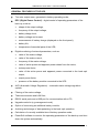
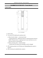
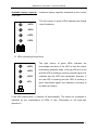
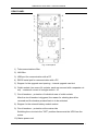
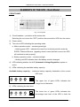
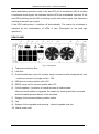
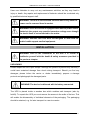
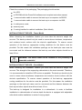
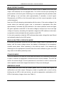
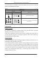
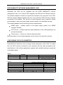
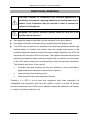
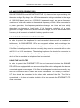
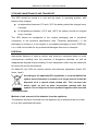
SINLINE Pro series UPS – Instruction Manual TABLE OF CONTENTS INTRODUCTION .................................................................................................................................................. 3 GENERAL INFORMATION ................................................................................................................................. 3 PURPOSE OF THE POWER SUPPLY ............................................................................................................. 3 GENERAL FEATURES OF THE UPS ............................................................................................................. 4 ELEMENTS OF THE UPS - Tower Model ............................................................................................................ 5 FRONT PANEL ................................................................................................................................................. 5 REAR PANEL ................................................................................................................................................... 7 ELEMENTS OF THE UPS - Rack Model .............................................................................................................. 8 FRONT PANEL ................................................................................................................................................. 8 REAR PANEL ................................................................................................................................................... 9 HEALTH AND SAFETY INSTRUCTIONS ....................................................................................................... 10 HANDLING ..................................................................................................................................................... 10 ELECTRIC SAFETY ....................................................................................................................................... 10 INSTALLATION.................................................................................................................................................. 11 UNPACKING .................................................................................................................................................. 11 INSTALLATION OF THE UPS - Tower Model ............................................................................................. 12 INSTALLATION OF THE UPS – Rack Model .............................................................................................. 12 THE BATTERY MODULE ............................................................................................................................. 13 Connecting the module ......................................................................................................................................... 14 Disconnecting the module ..................................................................................................................................... 14 EVER Management CARD .............................................................................................................................. 14 CONNECTING THE UPS ............................................................................................................................... 16 Input installation ................................................................................................................................................... 17 Output installation ................................................................................................................................................. 17 FIRST START ................................................................................................................................................. 19 DESCRIPTION OF THE BACK-UP'S OPERATION ......................................................................................... 19 GENERAL INFORMATION .......................................................................................................................... 19 MAINS OPERATION MODE ......................................................................................................................... 21 BACK-UP (BATTERY) OPERATION MODE .............................................................................................. 21 STAND-BY MODE ......................................................................................................................................... 21 EMERGENCY MODE .................................................................................................................................... 21 SAFEGUARDS ................................................................................................................................................ 22 COMMUNICATION VIA RS232 OR USB .................................................................................................... 23 INSTALLATION AND CONFIGURATION OF THE POWERSOFT PERSONAL SOFTWARE .............. 24 Installation on computers with Windows .............................................................................................................. 24 Installation on computers with Linux/Unix........................................................................................................... 25 Software Updates .................................................................................................................................................. 26 EVER SNMP/HTTP NETWORK MANAGEMENT CARD .......................................................................... 27 CONFIGURING THE UPS PARAMETERS .................................................................................................. 27 ADDITIONAL REMARKS.................................................................................................................................. 28 UPS AND POWER GENERATORS ............................................................................................................... 29 USING THE TELECOMMUNICATIONS FILTER ....................................................................................... 29 USING THE LAN FILTER ............................................................................................................................. 29 STORAGE, MAINTENANCE AND TRANSPORT ....................................................................................... 30 DISPOSAL ....................................................................................................................................................... 30 TECHNICAL PARAMETERS – Tower Model ................................................................................................... 31 TECHNICAL PARAMETERS – Rack Model ..................................................................................................... 32 INFORMATION REGARDING REGULATIONS AND WARRANTY ............................................................ 33 DECLARATION OF CONFORMITY ............................................................................................................ 33 WARRANTY ................................................................................................................................................... 33 2012/03/02 www.ever.eu 2 SINLINE Pro series UPS – Instruction Manual INTRODUCTION Thank you for purchasing the EVER SINLINE PRO UPS. It belongs to the latest series of state-of-the-art power supply devices designed to work with servers, computer networks, as well as workstations. When operating in the battery mode, the UPSs of this series generate true sine wave voltage at their output thanks to the Clear Digital Sinus (CDS) system and offer the feature of remote control of operating parameters via RS232 serial port or USB and optionally via the EVER control network adapter (Telnet, SNMP, HTTP). SINLINE PRO series EVER UPS was designed so as to meet all your expectations for protection against power loss. The UPS was manufactured in Poland and its structure conforms with requirements of the CE symbol. GENERAL INFORMATION PURPOSE OF THE POWER SUPPLY SINLINE PRO series UPS are LINE-INTERACTIVE (VI)-class devices designed for work with equipment powered by monophase ~230V mains. In back-up operation mode they generate true sine wave at their output. It enables a definite improvement of energy compatibility of the UPS and connected receivers. SINLINE PRO UPS do not switch off automatically even when there are no devices connected to the outlet sockets so they may even power devices with extremely low power consumption. Load power of this UPS is limited only at the upper extreme and the overload status is communicated visually, accoustically and via the PC software monitoring the device. Unlike quasi-sine wave UPS, the SINLINE PRO-series may power devices with induction motors. WARNING! SINLINE PRO UPS were not designed to work with life and/or health support medical equipment. 2012/03/02 www.ever.eu 3 SINLINE Pro series UPS – Instruction Manual GENERAL FEATURES OF THE UPS True sine output wave, generated in battery operating mode; DPC (Digital Power Control) – digital control of operating parameters of the back-up, such as: shape of the output voltage, frequency of the output voltage, battery charge level; battery voltage and current; measurement of battery charge (displayed on the front panel); battery life; temperature of essential parts of the UPS; Digital monitoring of external parameters, such as: value of the mains voltage, value of the mains current, frequency of the mains voltage, value of active power and apparent power drawn from the mains, mains power factor, value of the active power and apparent power connected to the back-up's output, output power factor, presence of the battery module connected to the UPS. AVR (Automatic Voltage Regulation) – automatic mains voltage regulation system; Filtering of the mains voltage, Telecommunication and LAN filter; RS232 serial ports and a USB port for communication with a PC; Upgrade card slot (e.g.management card); Option of connecting an additional battery module; Archiving and storage of data pertaining to the back-up's operation; Calculation of currently available time of battery operation mode; PowerSoft software to monitor the operating parameters of the back-up and shut down the system automatically. 2012/03/02 www.ever.eu 4 SINLINE Pro series UPS – Instruction Manual ELEMENTS OF THE UPS - Tower Model FRONT PANEL Fig. 1: Front panel 1) Power switch 2) Two-colour LED indicating the operating mode: a. Mains Operation Mode – constant green light – blinking green LED - indicates the need for a technical periodic review by EVER’s Technical Service (signaling doesn’t mean that fault occurs, the UPS will continue to work properly) b. Battery operation mode – constant red light – blinking red LED indicates that a flat battery must be changed 3) LED indicating whether the AVR (Automatic Voltage Regulation) system is activated. 4) LEDs indicating the available battery capacity. 2012/03/02 www.ever.eu 5 SINLINE Pro series UPS – Instruction Manual Available battery capacity – maximum battery capacity obtainable at the current UPS load. The left column of green LEDs indicates the charge >95% level of batteries. >80% >45% >20% + - 5) LEDs indicating the load level The right column of green LEDs indicates the >85% >60% >30% percentage load level of the UPS in both the mains and battery operation mode. If the top LED is lit in red and the UPS is emitting a continous sound signal, this indicates that the UPS has overloaded. However, if the red LED is blinking and the UPS is emitting a >5% quick intermittent signal, this indicates a shorting at the back-up's output. If the UPS malfunctions, it switches off automatically. The reason for shutdown is indicated by the combinations of LEDs lit (see "Description of the back-up's operation"). 2012/03/02 www.ever.eu 6 SINLINE Pro series UPS – Instruction Manual REAR PANEL Fig. 2: Rear panel 1) Telecommunications filter 2) LAN filter 3) USB port for communication with a PC 4) RS232 serial port for communication with a PC 5) Stopper for the upgrade card opening – internal upgrade card slot 6) Outlet sockets (two rows of 4 sockets, each row secured with a separate cutout) – maximum current of a single socket < 10 7) Circuit breakers – protection of individual rows of outlet sockets After the circuit breaker is triggered, the reason for shorting should be removed and the breaker pressed back in to be activated. 8) Stopper for the external battery module socket. 9) Circuit breakers – protection at the mains side Switching the cut-outs to the "OFF" position disconnects the UPS from the mains. 10) Mains power cord. 2012/03/02 www.ever.eu 7 SINLINE Pro series UPS – Instruction Manual ELEMENTS OF THE UPS - Rack Model FRONT PANEL Fig. 3: Front panel 1) Circuit breakers – protection at the mains side Switching the cut-outs to the "OFF" position disconnects the UPS from the mains. 2) Power switch 3) Two-colour LED indicating the operating mode: a. Mains operation mode – constant green light – blinking green LED - indicates the need for a technical periodic review by EVER’s Technical Service (signaling doesn’t mean that fault occurs, the UPS will continue to work properly) b. Battery operation mode – constant red light – blinking red LED indicates that a flat battery must be changed 4) LED indicating whether the AVR (Automatic Voltage Regulation) system is active. 5) LEDs indicating the available battery capacity. Available battery capacity – maximum battery capacity obtainable at the current UPS load. >20% >45% >80% >95% The upper line of green LEDs indicates the charge level of batteries. 6) LEDs indicating the load level The lower line of green LEDs indicates the >5% 2012/03/02 >30% >60% >85% percentage load level of the UPS in both the www.ever.eu 8 SINLINE Pro series UPS – Instruction Manual mains and battery operation mode. If the last LED is lit in red and the UPS is emitting a continous sound signal, this indicates that the UPS has overloaded. However, if the red LED is blinking and the UPS is emitting a quick intermittent signal, this indicates a shorting at the back-up's output. If the UPS malfunctions, it switches off automatically. The reason for shutdown is indicated by the combinations of LEDs lit (see "Description of the back-up's operation"). REAR PANEL Fig. 4: Rear panel 1) Telecommunications filter 2) LAN filter 3) Outlet sockets (two rows of 4 sockets, each row secured with a separate cut-out) – maximum current of a single socket < 10A 4) USB port for communication with a PC 5) RS232 serial port for communication with a PC 6) Circuit breakers – protection of individual rows of outlet sockets After the circuit breaker is triggered, the reason for shorting should be removed and the breaker pressed back in to be activated. 7) Stopper for the external battery module socket. 8) Fan 9) Stopper for the upgrade card opening – internal upgrade card slot 10) Mains power cord 2012/03/02 www.ever.eu 9 SINLINE Pro series UPS – Instruction Manual HEALTH AND SAFETY INSTRUCTIONS HANDLING exercise utmost caution when handling the device; do not handle heavy equipment by yourself; storage and operation of the device should take place in conditions conforming to its specification. ELECTRIC SAFETY Never work alone in conditions that may be hazardous to health and/or life; Even a momentary shorting of a strong current may lead to severe burns; Prior to connecting the device to the mains inspect the condition of power cords, plugs and sockets, as well as the condition of the device itself; To minimize the risk of electric shock, in cases when there is no way of verifying the earthing, the device should be disconnected from the mains before installation or connection of other equipment to the back-up – reconnect the power cord only after all connections are made; To avoid the risk of electric shock when connecting and disconnecting signal cables and touching two surfaces with differing electric potential, if possible use only one hand; The device must be plugged in to a three-lead installation (two poles and earthing) – failure to meet this requirement may result in electric shock; The installation must enable a complete disconnection of the UPS from the mains, e.g. by switching the S-type fuse; The device receiving the current must be connected with an appropriate circuit protection (manual cut-out or circuit breaker); The device has an earthing lead that carries away the leakage current from the receivers (e.g. computer equipment) – the total leakage current must not exceed 3.5mA. 2012/03/02 www.ever.eu 10 SINLINE Pro series UPS – Instruction Manual Users are forbidden to carry out any maintenance activities, as they may lead to injury or death. Any repairs and replacement of batteries should be conducted only by qualified technical support staff. WARNING! The UPS is disconnected from the mains only when the power cord is removed from its socket. WARNING! Since the device is equipped with internal power source (batteries) the output may provide hazardous voltage even though the device itself is not connected to the mains. WARNING! SINLINE PRO UPS were not designed to work with life and/or health support medical equipment. INSTALLATION WARNING! Prior to the installation of the UPS it is crucial to familiarise yourself with the health & safety measures provided in the previous chapter. UNPACKING Please inspect the UPS upon receipt. Although the product is packed very carefully it could have sustained damage from shock during transport. Should you find any damages, please inform the carrier or dealer immediately, prepare a damage protocol and photograph the damaged parts. WARNING! The device is delivered with its battery connected. The UPS is placed inside a wooden box which enables safe transport (also by forklift). To unpack the UPS you must remove the screws in the walls of the box. This will enable the disassembly of individual elements of the packaging. The packaging should be retained, e.g. for later transport to a service centre. 2012/03/02 www.ever.eu 11 SINLINE Pro series UPS – Instruction Manual Check the contents of the packaging. The packaging should contain: the UPS. a CD-ROM with the PowerSoft software and complete instruction manual, 1 communication cable to connect the back-up to a computer via RS232, 1 communication cable to connect the back-up to a computer via USB, 4 outlet power cords, warranty card, 2 moving handles for cabinet installation (Rack Model). INSTALLATION OF THE UPS - Tower Model When choosing the installation location you must take the device's weight into account. The back-up should only be used in rooms whose dustiness, temperature and moisture levels conform with the device's specification. To ensure correct operation of the back-up, appropriate cooling conditions for the device must be provided. For this reason the ventilation openings on the back-up's case must be uncovered and the distance between the back-up and other objects should be at least 10 cm. WARNING! The device must not be installed in the proximity of flammable materials! INSTALLATION OF THE UPS – Rack Model When choosing the installation location you must take the device's weight into account. The strength of the supporting cabinet/rack is the most essential. Therefore, it is recommended to install the UPS as low as possible. The back-up should only be used in rooms whose dustiness, temperature and moisture levels conform with the device's specification. To ensure correct operation of the back-up, appropriate cooling conditions for the device must be provided. For this reason the ventilation openings on the back-up's case must be uncovered and the distance between the back-up and other objects should be at least 10 cm. The back-up is designed for installation in a cabinet/rack. In order to facilitate installation in cabinets/racks of various depth the device is equipped with adjustable rails which enable installation in racks of varying depth. 2012/03/02 www.ever.eu 12 SINLINE Pro series UPS – Instruction Manual To install the UPS take the following steps: 1. Install the moving handles in the back section of the cabinet. 2. Supporting the back-ups base with your hand, slide UPS onto the previouslyinstalled handles. 3. Screw the front (fixed) handles of the UPS to the rack's frame. Fig. 5: SINLINE PRO 19" RACK 3U – Top View WARNING! The device must not be installed in the proximity of flammable materials! THE BATTERY MODULE SINLINE PRO UPS have the option of connecting an additional battery module. For this, the special connector located on the rear panel is used. Connecting a battery module extends the time of battery operation mode. The battery module is protected by an additional cut-out located inside the module. Replacement of cut-outs should be conducted only by a qualified representative of the technical support. WARNING! The given model of UPS may only be enhanced with battery modules recommended by the manufacturer (see: "Technical parameters"). 2012/03/02 www.ever.eu 13 SINLINE Pro series UPS – Instruction Manual Connecting the module 1. Turn the UPS off with the power switch on the front panel and switch the circuit breakers to the "OFF" position. 2. Remove the stopper covering the connector (rear panel). 3. Connect the battery module to the UPS. 4. Switch the circuit breakers to the "ON" position and then turn the UPS on with the power switch on the front panel. 5. Configure the number of battery modules in the PowerSoft software (for SINLINE PRO UPSs the maximum number is 1). 6. After the batteries are charged the UPS is ready for operation. WARNING! During the first charging of batteries the UPS must not be turned off with the power switch located on the front panel. This may lead to errors in the UPS calibration. Disconnecting the module 1. Turn the UPS off with the power switch on the front panel and switch the circuit breakers to the "OFF" position. 2. Disconnect the battery module from the UPS. 3. Secure the connector by replacing the protective stopper. 4. Switch the circuit breakers to the "ON" position and then turn the UPS on with the power switch on the front panel. 5. Configure the number of battery modules in the PowerSoft software (in the case of no modules set the parameter to 0). 6. After the batteries are charged the UPS is ready for operation. EVER Management CARD The EVER management card is an optional component that may be installed by the user. Installing the card renders the communication via RS232 and USB impossible. 2012/03/02 www.ever.eu 14 SINLINE Pro series UPS – Instruction Manual Installing the management card – Tower Model 1. Turn the UPS off with the power switch on the front panel and disconnect it from the mains by removing the power cord plug from the mains socket. 2. Remove the screws holding the cover of the card slot and remove the cover (Fig. 6a). 3. Connect the cable located in the opening to the card (Fig. 6b). 4. Slide the card into the slot (Fig. 6c). 5. Replace the screws, fixing the card to the rear panel (Fig. 6d). a. b. c. d. Fig. 6: Installation of the management card Installing the management card – Rack Model 1. Turn the UPS off with the power switch on the front panel and disconnect it from the mains by removing the power cord plug from the mains socket. 2. Remove the screws holding the cover of the card slot and remove the cover (Fig. 7a). 3. Connect the cable located in the opening to the card (Fig. 7b). 4. Slide the card into the slot (Fig. 7c). 5. Replace the screws, fixing the card to the rear panel (Fig. 7d). 2012/03/02 www.ever.eu 15 SINLINE Pro series UPS – Instruction Manual a. b. c. d. Fig. 7: Installation of the management card CONNECTING THE UPS The power cord that comes with the UPS has no plug and it needs to be connected to the mains by fixing the tips of individual wires to the connector. All wires are marked appropriately: L – live wire (brown), N – neutral wire (blue), PE – earthing (yellow-green). Wire diameter – 2.5 sq mm. The arrangement of the installation must enable disconnecting the section where the UPS is connected from the mains, e.g. by turning overcurrent switches. WARNING! Connecting of the UPS to the mains should be performed only by qualified and authorised personnel. WARNING! The UPS is disconnected from the mains only when the power cord is removed from its socket. 2012/03/02 www.ever.eu 16 SINLINE Pro series UPS – Instruction Manual It is recommended to use the safety circuits of the building as one of the protection measures. Protection parameters of the buildings' installations should be adjusted accordingly to the type and size of load connected to the installation. Differing characteristics of protections of installations in the building and the UPS may in extreme cases lead to quicker responses of the former. Input installation Fig. 8 presents the ways of correct connection of the UPS to different types of mains (TN-S or TN-C-S) that vary with regard to the manner of earthing. Fig. 8: Input installation of the UPS Output installation Even though the input side allows both types of terminals, the output installation arranged inconsistently with this instruction may damage the UPS. The diagram of correctly arranged output connections is presented in Fig. 9. WARNING! The output side of the back-up only allows the TN-S mains configuration. 2012/03/02 www.ever.eu 17 SINLINE Pro series UPS – Instruction Manual Fig. 9: Output installation of the UPS The arrangement of terminals of output sockets of the UPS is presented on Fig. 10. Fig. 10: Arrangement of terminals of output sockets After unpacking the device should be placed in the chosen location, power supply to the connection should be cut off and the UPS connected to the mains. After the backup is correctly connected to the mains, the power supply may be switched back on. Make sure the S-type circuit breakers located on the UPS are switched to the "ON" position. 2012/03/02 www.ever.eu 18 SINLINE Pro series UPS – Instruction Manual FIRST START At the first start the UPS may require to be left connected to the mains in order to allow the internal batteries to charge. The power switch on the front panel should be turned to the "ON" position. Charging time of batteries is presented in the technical parameters table. Afterwards, the user may continue with the installation procedure. Take the following steps: Turn the UPS off with the power switch on the front panel (only if it was turned on), connect the devices that require buffer power supply (e.g. computer and monitor) to the outlet sockets on the UPS, connect the UPS to the computer (use one of the two available connections: RS232 or USB), turn on the UPS with the switch on the front panel, turn on the devices connected to the UPS, install the monitoring software on the control computer (see chapter "Installation of the PowerSoft software"). With all of the above actions complete the UPS is ready for operation. WARNING! The UPS reach their full capacity after approximately a month of mains operating mode. DESCRIPTION OF THE BACK-UP'S OPERATION GENERAL INFORMATION The SINLINE PRO UPS is a state-of-the-art electronic device constituting an autonomous source of true sine wave voltage of 230V. This device belongs to the group of LINE-INTERACTIVE (VI)-class UPSs, which includes UPS that synchronise with the mains. The UPS is equipped with the CLEAR DIGITAL SINUS (CDS) system, which generates a precisely stabilised output voltage in the shape of sinusoid, which enables supplying power to a wide range of equipment that do not tolerate quasi-sine wave voltages. This system increases the reliability of the device and guarantees stable operation of the UPS. 2012/03/02 www.ever.eu 19 SINLINE Pro series UPS – Instruction Manual With the help of the Automatic Voltage Regulation (AVR) system the UPS instantly corrects slight drops in mains voltage to provide the receivers with appropriate power supply conditions without tapping into the energy reserves stored in the batteries. The back-up also uses the system of advanced DIGITAL POWER CONTROL (DPC) which precisely shapes the oscillation of the output voltage to obtain a clear sinus. In the mains operating mode the system filters the mains voltage to remove the noise and distortions that may be dangerous for the receivers. The dedicated DPC system monitors the operation of the UPS; it has a precise and very quick-reacting system of detecting overloads and outlet shorting in the backup operation mode. In mains operation mode the shorting safeguard is provided by cutouts and overloads are signalled both visually and acoustically. When the UPS is started in the back-up operation mode a special soft start mode is used in order to launch with high loads that draw high starting current, e.g. laser printers. Moreover, the DPC system enables long operation in battery mode by allowing connection of an additional battery module and control of internal temperature by means of an active cooling system, which is activated as necessary. This manner of switching on the cooling reduces the amount of noise generated by the UPS. The DPC system offers various modes of communication between the UPS and the computer via a communication port or a special slot for The EVER management card (HTTP, telnet, SNMP). The UPS conducts precise measurements of its basic parameters, such as battery voltage, mains input voltage, output voltage of the UPS, power of the load connected, temperature and advanced parameters (measurement of available battery capacity, remaining time of battery operation mode with the current load). This UPS utilises an innovative charging method reserved only for the most advanced UPS (CBC - COOL BATTERY CHARGING) which utilises the elements of an internal inverter. During the mains operation mode it charges the batteries and in the back-up operation mode it converts the internal energy of the battery into the alternating current to power the protected devices. 2012/03/02 www.ever.eu 20 SINLINE Pro series UPS – Instruction Manual MAINS OPERATION MODE Connecting the UPS to the mains does not cause current to appear at the back-up's output. UPS batteries are not charged either. The UPS is turned upon pressing the power switch on the front panel. Switching on is accompanied by the operation mode LED lighting in red and then (after approximately 3 seconds) a sound signal. Subsequently, all LEDs on the front panel light up so their correct operation can be verified (autotest). Next, the UPS will attempt synchronisation with the mains. If the mains voltage of the socket where the back-up's power cord is connected is appropriate then after approximately 5 seconds the UPS switches to the mains operation mode and lights the green operation mode LED. If the mains voltage is incorrect (too low or too high voltage or frequency exceeding the operation range) the UPS switches to the backup operation mode and lights the red operation mode LED. In the mains operation mode the UPS outlet provides mains voltage that was filtered and optionally raised by the AVR system. BACK-UP (BATTERY) OPERATION MODE In the back-up operation mode the true sine wave voltage output is generated by the battery until the mains voltage returns, the battery is discharged or an emergency situation takes place. When operating in the back-up mode, if the batteries are discharged or the appropriate command from the control software is given, the UPS may switch to the battery stand-by mode. STAND-BY MODE The UPS switches to STAND-BY mode when the batteries are completely discharged or when it receives an appopriate command from the control software. The UPS will wait for the mains voltage of correct parameters to come back in order to return to the mains operation mode and charges the batteries if they were discharged. EMERGENCY MODE In this mode the UPS cuts the power power from its outlets and signals all malfunctions and their origins. Emergency mode is signalled with a sound and by blinking the red LED in the load column, as well as appropriate combinations of lit LEDs in the battery charge column (see Table 1). 2012/03/02 www.ever.eu 21 SINLINE Pro series UPS – Instruction Manual The UPS remains in emergency mode until switched off by the user or until the batteries are completely discharged. Table 1 ERROR TABLE Signalling Type of error Tower Rack UPS connected incorrectly - + Internal errors (a combination of lit LEDs indicates + - + - + - various errors) 1) 1) Information for the tech support SAFEGUARDS Against overloads An overload is signalled by constant shining of the last LED (red) in the load indication column and a continuous sound signal. If the UPS is operating in back-up mode and the overload lasts longer than 10 seconds the UPS will switch to emergency operation mode. Outlet sockets are disconnected from the power supply. Against shorting In the mains operation mode the safeguard against shorting is provided by the cutouts located in the rear section of the UPS. In the battery operation mode the electronic shorting safeguard reduces the shortcircuit current to a safe level by lowering the output voltage. When the shorting occurs in the back-up operation mode, it is signalled by the UPS with a quick blinking of the last LED (red) in the load indication column and a quick, intermittent sound signal. If the shorting lasts longer than 1 second, the UPS will switch to the emergency operation mode. 2012/03/02 www.ever.eu 22 SINLINE Pro series UPS – Instruction Manual Against overvoltage The UPS is equipped with anti-overvoltage safeguard at the input which protects the circuits of receivers and the internal circuits of the UPS against high-energy current rushes caused by atmospheric phenomena and power grid disruptions. Against incorrect connection Incorrect connection of the UPS causes it to switch to emergency operation mode the moment it is switched on. This is signalled by slow blinking of the last LED (red) in the load indication column and an intermittent sound signal mirroring the rate of blinking. In addition, the layout of lit LEDs in the battery charge level column indicates the type of error. (see the Error Codes table) COMMUNICATION BETWEEN THE UPS AND A COMPUTER COMMUNICATION VIA RS232 OR USB SINLINE PRO series UPS come with enhanced control features. The UPS is delivered with a built-in RS232 and USB communication port and the PowerSoft software package. To ensure correct cooperation the UPS must be connected to the computer with the provided cable. WARNING! The communication connection between the UPS and the computer should be made only if the user intends to use the control software. If the software is not installed while the connection is made then the RS232 or USB port may receive random conditions (PNP or others) which may lead to incorrect operation of the UPS. WARNING! Only one type of connection may be used at any given time. 2012/03/02 www.ever.eu 23 SINLINE Pro series UPS – Instruction Manual INSTALLATION AND CONFIGURATION OF THE POWERSOFT PERSONAL SOFTWARE Installation on computers with Windows Prior to beginning the installation of PowerSoft: Uninstall the current version of PowerSoft or any other control software (in situations where the user is changing the UPS protecting the computer), If the installed UPS communicates with the PC via a USB cable, this cable should be disconnected from the computer. The software installer will prompt the user to connect the communication cable at the appropriate time. To install PowerSoft on a computer with Windows (the list of operating systems compatible with the application is available at www.ever.eu) just run the software installer and follow the instructions onscreen. During the installation you will be asked to select the model of the UPS connected to the computer on which the software is being installed. This setting may also be changed when the application is running. In the case of a UPS connected to the computer via a USB cable, when the software installation is complete, the PowerSoft installer will ask the user to connect the USB cable to the computer. The system will announce that a new device has been found and will propose to install the drivers. Select the option to install the drivers from a chosen location and on the next screen indicate the installation folder of the PowerSoft software (usually C:\Program Files\PowerSoft) to be searched. Next, the operating system will locate and install the appropriate driver. In the case of Windows Vista the operating system will not initiate automatic installation of the drivers from the hard drive. After connecting the USB cable to the computer you will need to open the control panel from the Start Menu and select system properties. On the device tree displayed find the USB bus branch (in most cases it will be already expanded) and select the ups. Update the device's driver from it's "Properties" window by right-clicking it in the list and following the instructions onscreen. As the driver's location you should indicate the PowerSoft installation folder (usually C:\Program Files\PowerSoft). To uninstall PowerSoft select the "Uninstall PowerSoft" option in Start Menu. You can also uninstall PowerSoft from the "Add and remove programs" menu in the control panel. 2012/03/02 www.ever.eu 24 SINLINE Pro series UPS – Instruction Manual Installation on computers with Linux/Unix The binary version of the application for Linux/Unix systems is provided in the following formats: CentOS, RedHat, Suse Linux, Fedora Core For the CentOS, RedHat, Suse Linux, and Fedora Core systems the software is provided in the form of a RPM package. The software can be installed by using any package manage available for the system installed. If you are using the command line, the software is installed by entering the following command: rpm –ivh PowerSoftpersonal-x.x.x.i386.rpm Users working with the PowerSoft must have root privileges to install the software and use it. After installation the application may be found in the /usr/local/PowerSoft directory. To uninstall the application enter the following command: rpm –ev PowerSoftpersonal-x.x.x Debian For Debian systems the software is provided in the form of a DEB package. The software is installed via the following command: dpkg –-install PowerSoftpersonal-x.x.x.deb To uninstall the application enter the following command: dpkg –-remove PowerSoft FreeBSD For FreeBSD systems the software is provided in the form of the default package format designed for FreeBSD systems. The software is installed via the following command: pkg_add PowerSoftpersonal-x.x.x.tbz To uninstall the application enter the following command: pkg_delete PowerSoft 2012/03/02 www.ever.eu 25 SINLINE Pro series UPS – Instruction Manual WARNING! FreeBSD systems do not support communication with the UPS via the USB cable. Starting the software When the installation is complete, the system service is started automatically, while the control panel application can be found at /usr/local/PowerSoft. Please note that for the Polish diacritics to be correctly displayed the system locale should be Polish. Software Updates Windows systems The software installer for Windows systems has a built-in automatic updater. PowerSoft can regularly check for new software versions and notify the user when updates are available. By default the software checks for updates after the user logs in. This setting can be changed under the "Update configuration" tab in the system's programme menu. Linux/Unix systems In the case of Linux/Unix systems PowerSoft can be updated by downloading the new package from www.ever.eu. In the case of CentOS, RedHat, Suse Linux, and Fedora Core PowerSoft can be updated by entering the following command: rpm –Uv PowerSoftlite-x.x.x In the case of Debian and FreeBSD systems we recommend uninstalling the old version and then installing the new version of the software. Commands which enable these operations are described in the instruction manual available at www.ever.eu. 2012/03/02 www.ever.eu 26 SINLINE Pro series UPS – Instruction Manual EVER SNMP/HTTP NETWORK MANAGEMENT CARD Optionally, the UPS can be upgraded with the EVER SNMP/HTTP network management card. It is a device that integrates the UPS with an Ethernet network. The network adapter is located in a special slot located on the rear panel of the UPS. With the network adapter installed, the user can control the UPS from any computer connected to the network. This solution is most frequently used in cases of central power supply or when the power supply system needs to be controlled remotely. The network adapter has the following services implemented: SNMP agent – enables control of the power supply system via a SNMP manager software; HTTP server – enables inspection and modification of the UPS parameters via an Internet browser; Telnet server – control via a Telnet network terminal. More information on the network adapter can be found in its instruction manual. CONFIGURING THE UPS PARAMETERS PowerSoft Plus allows the user to change certain parameters of the UPS. To enable this, the UPS must be connected to the computer with the cable provided by the manufacturer. A list of these parameters together with available settings is presented in the tables below. Table 2 Acoustic signalling FACTORY SETTING On Delay before standby mode 90 sec. PARAMETER/FUNCTION USER CHOICE On/off 0 – 1000 sec. DESCRIPTION Only for the battery operation mode Time between system shutdown and the UPS switching to standby mode Table 3 THRESHOLD (SWITCHING) VOLTAGE Range Default setting BAT → MAINS + AVR ~155 ÷175 V ~165 V MAINS + AVR → BAT ~150 ÷170 V ~160 V MAINS + AVR → MAINS ~200 ÷210 V ~205 V MAINS → MAINS + AVR ~195 ÷205 V ~200 V MAINS → BAT ~250 ÷280 V ~265 V BAT → MAINS ~245 ÷275 V ~260 V BAT – battery operation mode; MAINS – mains operation mode; MAINS + AVR – mains operation mode with AVR system engaged UPS STATUS 2012/03/02 www.ever.eu 27 SINLINE Pro series UPS – Instruction Manual ADDITIONAL REMARKS CAUTION: Product for commercial and industrial applications in secondary environment. Applying additional preventive measures or limiters in the installation may be required in order to prevent the emission of disruptions. WARNING! No service elements located inside the UPS are to be modified by the end user. Damaging the warranty seal shall void the warranty for the given device. Any repairs should be conducted only by qualified technical support staff. The UPS may not perform as expected if the powered equipment draws high impulse power. In practice, this means that even though mean power of the protected equipment does not exceed the power range accepted by the UPS, the equipment will cause the UPS to shut down. This happens because the protected equipment temporarily draws power that significantly exceeds the nominal power of the UPS, which causes an overload detection and consequently a shutdown. This situation may occur in the case of: Television sets and monitors (as they are switched on the picture tube is degaussed which temporarily requires a lot of power), Laser printers (drum warming cycle), Other products with similar operating features. Therefore, if a UPS is to be used with equipment other than computers, its compatibility with equipment used must be verified. In order to do this, all devices should be connected to the UPS and its operation should be observed in all modes, i.e. start-up, shutdown, stand-by, etc. 2012/03/02 www.ever.eu 28 SINLINE Pro series UPS – Instruction Manual UPS AND POWER GENERATORS SINLINE PRO UPSs are LINE-INTERACTIVE (VI) class devices synchronising with the mains voltage. By design, the UPS tolerates mains voltage variations in the range of ~160-264V (basic range) or ~150÷280V (enhanced range), as well as frequency variations of ±5Hz with relation to the nominal frequency of 50Hz. When connected to a power generator, the frequency variations change over time and are strictly dependent on changes in load levels. If the frequency variations of a power generator's voltage exceed the allowed tolerance range, the UPS will consider such frequency to be incorect and switch to battery operation mode. USING THE TELECOMMUNICATIONS FILTER In order to protect the telephone line and connected devices such as modems or telephones, the SINLINE PRO UPSs are equipped with an anti-overvoltage filter which safeguards the devices connected against overvoltages in the telephone line. If the filter is to safeguard the devices correctly, they must be connected with a cable with RJ11 or RJ12 terminators. The existing telephone line should be connected to the other outlet socket of the filter. The filter is symmetrical, so it does not matter to which of the two sockets the telephone line is connected. USING THE LAN FILTER In order to protect the ETHERNET UTP line and connected devices, the SINLINE PRO UPSs are equipped with an anti-overvoltage filter which safeguards the devices connected against overvoltages. If the filter is to safeguard the devices correctly, they must be connected with a cable with RJ45 terminators. The existing ETHERNET UTP line should be connected to the other outlet socket of the filter. The filter is symmetrical, so it does not matter to which of the two sockets the ETHERNET UTP line is connected. 2012/03/02 www.ever.eu 29 SINLINE Pro series UPS – Instruction Manual STORAGE, MAINTENANCE AND TRANSPORT The UPS should be stored in a cool and dry place, in operating position, with batteries fully charged: In temperatures between 0°C and +30°C the battery should be charged every 6 months; In temperatures between +30°C and +45°C the battery should be charged every 3 months. The UPS should be transported in the original packaging and in conditions conforming to the product's specification (see "Technical parameters"). If the packaging is missing or a non-original or incomplete packaging is used, EVER Sp. z o.o. shall not be liable for any mechanical damages that occur in transport. DISPOSAL Appropriate disposal of used-up electric and electronic equipment helps to avoid consequences resulting from the presence of dangerous materials, as well as inappropriate disposal and processing of such equipment, which may be hazardous to human life and the environment. Act dated 29 July 2005 on used-up electric and electronic equipment, Article 22.1 items 1 and 2. According to the applicable EU regulations, a crossed rubbish bin symbol means that when a product is no longer used it should be disposed of at a special waste pickup site. This concerns the device itself, as well as other accessories marked with this symbol. Do not dispose of those products together with unsorted household waste. Method of safe removal of the batteries from the appliance: The batteries should be removed from the appliance by an authorised service outlet or by a duly authorised electrician. 2012/03/02 www.ever.eu 30 SINLINE Pro series UPS – Instruction Manual TECHNICAL PARAMETERS – Tower Model PARAMETERS / UPS TYPE Output power 1) Working environment Operating temperature 2) Storage temperature Relative humidity for operation Relative humidity for storage Altitude (above sea level) 3) Maximum length of outgoing cables MAINS OPERATION MODE Input voltage 4), 5) Frequency of input voltage Range of output voltage 5) Switching thresholds: Mains – UPS 4), 5) Shape of output voltage Filtering of output voltage Time to switch to UPS BACK-UP (BATTERY) OPERATION MODE Output voltage (effective value) Shape of output voltage Switching thresholds: UPS– mains 4), 5) Frequency of output voltage Filtering of output voltage Shorting safeguard Overload protection Time to switch back to mains operation Support time with internal batteries only (100%/80%/50%Pmax) Support time with battery module installed (100%/80%/50%Pmax) Battery Additional modules Maximum charging time of internal batteries SINLINE PRO SINLINE PRO SINLINE PRO SINLINE PRO model 2200 model 3000 model 4000 model 5000 2200 VA 3000 VA 4000 VA 5000 VA 2000 W 2800 W 3000 W 3250 W Office or industrial rooms with low level of pollution +10 ÷ +35 °C 0 ÷ +45°C 20 ÷ 80 % (without condensation) 20 ÷ 95 % (without condensation) up to 1000 m < 10 m ~150 ÷ 280 V (~160 ÷ 265 V) ± 2 % 45 ÷ 55 Hz ± 1 Hz ~172 ÷ 280 V (~184 ÷ 265 V) ± 2 % ~150 ÷170 V (~160 V) / ~255 ÷280 V (~265 V) ± 2 % Same as input Noise filter RFI/EMI varistor damper <3 ms ~230 V ± 5 % Sinus ~155 ÷175 V (~165 V) / ~250 ÷275 V (~260 V) ± 2 % 50 Hz ± 1 Hz LC Electronic Electronic 0 ms 8/11,5/28 5,5/7,5/16 5/7/14 4,5/6,5/12 min min min min 60/65/130 34/39/88 30/36/80 28/32/75 min min min min 2x 4x VRLA 12V/9 Ah 4x 4x VRLA 12V/9 Ah 6) Maximum charging time of internal batteries + battery module 6) MECHANICAL PARAMETERS Dimensions (h x w x d) UPS weight Battery module weight EQUIPMENT Outlet sockets Signalling <3h < 10 h 380 x 170 × 600 mm 65 kg 65 kg 8 x IEC320 C13 Acoustic and visual (LEDs) 2 x 15A circuit breaker – protection of outlet sockets Cut-out 2 x 32A circuit breaker – protection at the mains side Available Telecommunications filter Available LAN filter RS232, USB, SNMP/HTTP network management card – optional Communication interface Note: The manufacturer reserves the right to change the abovementioned parameters without prior notice. Notes: 1) For normal operation of the UPS the load connected to its output should not exceed 80% of value indicated in the table. Reserve power is essential to ensure continuous operation of connected devices in case of momentary rushes in load current. 2) Continued exposure of the UPS to the temperature of the surrounding exceeding +25°C will shorten the life of batteries. 3) If the altitude above sea level increases beyond the provided limit the permitted load power of the batter back-up decreases. 4) The User may modify the switching thresholds. 5) Factory setting is provided in parentheses. 6) After discharging the UPS with power 80% Pmax, charging the battery to 90% capacity 2012/03/02 www.ever.eu 31 SINLINE Pro series UPS – Instruction Manual TECHNICAL PARAMETERS – Rack Model PARAMETERS UPS TYPE Output power 1) Working environment Operating temperature 2) Storage temperature Relative humidity for operation Relative humidity for storage Altitude (above sea level) 3) Maximum length of outgoing cables MAINS OPERATION MODE Input voltage 4), 5) Frequency of input voltage Range of output voltage 5) Switching thresholds: Mains – UPS 4), 5) Shape of output voltage Filtering of output voltage Time to switch to UPS BACK-UP (BATTERY) OPERATION MODE Output voltage (effective value) Shape of output voltage Switching thresholds: UPS– mains 4), 5) Frequency of output voltage Filtering of output voltage Shorting safeguard Overload protection Time to switch back to mains operation Support time with internal batteries only (100%/80%/50%Pmax) Support time with battery module installed (100%/80%/50%Pmax) Battery Additional modules Maximum charging time of internal batteries 6) Maximum charging time of internal batteries + battery module 6) MECHANICAL PARAMETERS Dimensions (h x w x d) UPS weight Battery module weight EQUIPMENT Outlet sockets Signalling SINLINE PRO SINLINE PRO SINLINE PRO SINLINE PRO 19” RACK 3U 19” RACK 3U 19” RACK 3U 19” RACK 3U model 2200 model 3000 model 4000 model 5000 2200 VA 3000 VA 4000 VA 5000 VA 2000 W 2800 W 3000 W 3250 W Office or industrial rooms with low level of pollution +10 ÷ +35 °C 0 ÷ +45°C 20 ÷ 80 % (without condensation) 20 ÷ 95 % (without condensation) up to 1000 m < 10 m ~150 ÷ 280 V (~160 ÷ 265 V) ± 2 % 45 ÷ 55 Hz ± 1 Hz ~172 ÷ 280 V (~184 ÷ 265 V) ± 2 % ~150 ÷170 V (~160 V) / ~255 ÷280 V (~265 V) ± 2 % Same as input Noise filter RFI/EMI varistor damper <3 ms ~230 V ± 5 % Sinus ~155 ÷175 V (~165 V) / ~250 ÷275 V (~260 V) ± 2 % 50Hz ± 1 Hz LC Electronic Electronic 0 ms 8/11,5/28 5,5/7,5/16 5/7/14 4,5/6,5/12 min min min min 60/65/130 34/39/88 30/36/80 28/32/75 min min min min 2x 4x VRLA 12V/9 Ah 4x 4x VRLA 12V/9 Ah <3h < 10 h 3U × 19” × 660 mm 63 kg 63 kg 8 x IEC320 C13 Acoustic and visual (LEDs) 2 x 15A circuit breaker – protection of outlet sockets Cut-out 2 x 32A circuit breaker – protection at the mains side Available Telecommunications filter Available LAN filter RS232, USB, SNMP/HTTP network management card – optional Communication interface Note: The manufacturer reserves the right to change the abovementioned parameters without prior notice. Notes: 1) For normal operation of the UPS the load connected to its output should not exceed 80% of value indicated in the table. Reserve power is essential to ensure continuous operation of connected devices in case of momentary rushes in load current. 2) Continued exposure of the UPS to the temperature of the surrounding exceeding +25°C will shorten the life of batteries. 3) If the altitude above sea level increases beyond the provided limit the permitted load power of the batter back-up decreases. 4) The User may modify the switching thresholds. 5) Factory setting is provided in parentheses. 6) After discharging the UPS with power 80% Pmax, charging the battery to 90% capacity. 2012/03/02 www.ever.eu 32 SINLINE Pro series UPS – Instruction Manual INFORMATION REGARDING REGULATIONS AND WARRANTY DECLARATION OF CONFORMITY The UPS was manufactured in Poland and its structure conforms to appropriate subject matter standards. WARRANTY A separate document attached to the product constitutes the warranty. The document must meet all formal requirements (e.g. the following fields must be populated: serial number, model/type, date of sale, and dealer stamp). The manufacturer made all efforts to ensure that products offered are free of material and workmanship defects throughout the term specified in the warranty document. The company's liability under the warranty shall be limited to repairs or replacement of products with such defects. The manufacturer shall make the decision as to how the defect is removed. The warranty shall not cover devices with mechanical damages that occurred as a result of negligence of incorrect use nor devices subjected to any modifications made by the user. Apart from the arrangements included in the warranty card EVER Sp. z o.o. shall not grant any guarantee or warranty, including warranty of merchantability or fitness for particular purpose. Apart from the arrangements included in the warranty card EVER Sp. z o.o. shall not be liable for direct, indirect, specific, incidental or consequential losses incurred in the course of using the UPS, even in cases when the buyer was warned about such losses being a possibility. The company shall not be liable for any costs, such as loss of profit or revenue, cost of equipment, costs of equipment use, costs of software, data, replacement products, claims of third parties or other costs. A separate document attached to the product constitutes the warranty. The document must meet all formal requirements (e.g. date of sale, dealer stamp). 2012/03/02 www.ever.eu 33