1
Instruction manual for Powerline RT
TABLE OF CONTENTS
TABLE OF CONTENTS ........................................................................................................................................ 2
PRODUCT INTRODUCTION ............................................................................................................................... 3
HOW IT WORKS .............................................................................................................................................. 3
SYMBOLS USED.............................................................................................................................................. 6
INSTRUCTIONS ABOUT FRONT PANEL INDICATORS ............................................................................. 7
REAR PANEL.................................................................................................................................................. 12
PRODUCT SPECIFICATIONS ....................................................................................................................... 17
INSTALLATION .................................................................................................................................................. 21
SAFETY DURING INSTALLATION ............................................................................................................. 21
UNPACKING AND CONTROL...................................................................................................................... 23
UPS and external battery pack vertical installation............................................................................................... 25
POWER SUPPLY CONNECTION.................................................................................................................. 26
Connecting an external battery pack ..................................................................................................................... 26
UPS power connection.......................................................................................................................................... 27
OPERATION ........................................................................................................................................................ 27
SAFE OPERATION INSTRUCTIONS ........................................................................................................... 27
STARTING THE UPS...................................................................................................................................... 28
Initial UPS start procedure .................................................................................................................................... 28
Regular UPS start procedure................................................................................................................................. 29
BYPASS MODE PROCEDURES.................................................................................................................... 29
ECO MODE PROCEDURE ............................................................................................................................ 30
FREQUENCY CONVERTER MODE PROCEDURE .................................................................................... 30
UPS STOP PROCEDURE ............................................................................................................................... 30
REMOTE POWER SUPPLY OFF (EPO) / REMOTE ON/OFF (ROO) ......................................................... 30
BATTERY MAINTENANCE............................................................................................................................... 31
CLEANING ..................................................................................................................................................... 31
UPS STORAGE ............................................................................................................................................... 31
BATTERY TESTING....................................................................................................................................... 32
BATTERY REPLACEMENT .......................................................................................................................... 32
External UPS battery pack replacement................................................................................................................ 32
TROUBLESHOOTING........................................................................................................................................ 36
TRANSPORT AND STORAGE ........................................................................................................................... 37
LAWS, REGULATIONS AND THE WARRANTY............................................................................................. 37
WARRANTY ................................................................................................................................................... 37
2011/04/19
www.ever.eu
2
Instruction manual for Powerline RT
PRODUCT INTRODUCTION
HOW IT WORKS
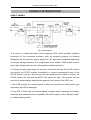
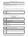
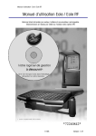
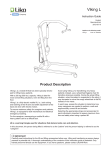
Fig.1: Block diagram
● A series of double-conversion on-line topology UPS, which provides excellent
protection for the connected receivers, such as computer systems, by filtrating
disruptions on the receiver's power supply line. AC input can be adjusted depending
on the grid voltage waveform; it is a high-power factor system. PWM control ensures
that output voltage can have an undisrupted and stable waveform.
● If the power grid parameters are incorrect, the driver will stop the AC/DC section
and launch the DC/DC section immediately to ensure uninterrupted work of the
DC/AC section (inverter). When the power grid parameters are back to regular, the
DC/DC section will stop and the AC/DC will resume its work. This ensures that the
receiver is uninterruptedly supplied with power by the inverter if the UPS is on.
● The UPS ensures an internal bypass to allow the receivers to obtain power grid
input when the UPS is damaged.
● The UPS is fitted with an internal battery charger, which recharges the battery
when the grid parameters are acceptable, with the exception of the "backup mode",
or "battery testing mode".
2011/04/19
www.ever.eu
3
Instruction manual for Powerline RT
MODE DESCRIPTION
● Stand-by mode
The UPS is deactivated, output disconnected (no power supply).
● Bypass mode
The bypass mode means that the UPS provides power supply to the receiver directly
through the internal bypass, without regulation. If the driver detects incorrect power
supply parameters, the output is disconnected and the UPS goes into the bypass
mode to protect the receiver. The user can enforce the bypass mode using buttons
on the front panel. In the bypass mode, most UPS settings can be changed with the
panel or communication software.
● Power grid mode
In the power grid mode, the input current is rectified/converted by the AC/DC section,
and then converted into stable output current by the DC/AC section, supplying the
current to the receivers. If the grid parameters become incorrect, the UPS
uninterruptedly switches to the backup mode.
● Backup mode
In the backup mode, power supply from the battery goes through the DC/DC section
to the inverter (DC/AC), where stable output voltage is generated. If the grid
parameters go back to normal, the UPS uninterruptedly switches to the grid mode.
● Frequency conversion mode
UPS may be used as a frequency converter, providing 50 Hz or 60 Hz at the output
(depending on the choice), on the condition that the frequency of the input current is
within 40 – 70 Hz.
If the device operates in the frequency conversion mode, the available supply power
is reduced by 50%. This means that only 50% of the UPS rated power can be used
when the device is in this mode.
If the device is used as a frequency converter, the ECO mode cannot be activated,
and the bypass mode cannot be used.
NOTE: The frequency conversion mode can be switched on/off only
when the device is in the standby mode.
2011/04/19
www.ever.eu
4
Instruction manual for Powerline RT
● ECO mode
When the ECO mode is one and the grid supply parameters are within the tolerance,
the output is supplied with power directly from the input, using the internal bypass.
The device in this mode is highly efficient while saving the energy. When the ECO
mode is on and the grid supply parameters are not within the tolerance, the device
automatically begins to supply power to the receiver using the inverter.
If the UPS is in the ECO mode, the internal battery charger is working.
● Error mode
If there is an internal error in the UPS and it is necessary to switch off the inverter, the
UPS switches to the error mode, producing a sound, and the relevant message on
the LCD panel is displayed. In the error mode, there is a risk of losing the power
supply by receivers, because the output voltage will be generated through the bypass
only after the error is actually encountered by the UPS.
● Extra functions
a) Green Power function (energy saving mode) If the device is in the backup mode
and no receiver is connected to the output, or the load is smaller than the predefined
threshold (see table of parameters), the UPS will switch off automatically after five
minutes in order to save the battery and energy.
b) Cold Start – if the function is switched on, it is possible to start the UPS without
power supplied from the grid, and the receiver is supplied directly from the battery.
NOTE: If the UPS is started for the first time, AC power supply must be
connected.
c) Automatic restart - if the function is switched on, after the autonomous power
supply time has lapsed, the device automatically starts when the grid power supply
resumes. If it doesn't, it is necessary to start the device manually.
2011/04/19
www.ever.eu
5
Instruction manual for Powerline RT
NOTE: if the function is activated and a failure of power supply occurs immediately
after the automatic start of the device, the autonomous power supply time will be
short, because the batteries have not been fully charged.
d) The battery test can be performed in two ways: manually or automatically, with a
fixed break between the tests.
e) Controlled outputs: the UPS is provided with two groups of controlled output
sockets (output 1 and output 2). Each group can be configured so that it
automatically switches off when the battery charging status drops below a specific
value (75%, 50%, 25% or 0%), or on the user's demand.
NOTE: It is recommended that key devices should be connected to the
main outputs, and less important ones to the controlled outputs.
f) Remote control - there are terminals on the rear panel of the UPS which enable the
user to switch on/off the device remotely (ROO), or switch off the device remotely
without the automatic restart option (EPO).
g) Compatibility with power generators – the UPS can work with most power
generators available on the market.
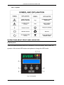
SYMBOLS USED
Some or all of the symbols below may be used in this instruction manual. It is
recommended that the user is familiar with the symbols and their meanings.
2011/04/19
www.ever.eu
6
Instruction manual for Powerline RT
Table 1. Symbols
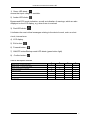
INSTRUCTIONS ABOUT FRONT PANEL INDICATORS
Control panel
There are several switches and LED indicators on the front panel, which notify the
operator of the current UPS status and options to change the UPS mode:
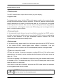
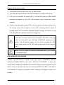
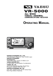
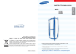
Fig. 2: Front panel
2011/04/19
www.ever.eu
7
Instruction manual for Powerline RT
1) Green LED diode means that input voltage is available.
2) Amber LED diode Bypass and ECO mode indication, as well as indication of warnings, which are also
displayed on the LCD display, e.g. when there is overload
3) Red LED diode It indicates the most critical messages relating to the device's work, such as: short
circuit, internal error
4) LCD display
5) Exit button 6) Forward button 7) ON/OFF button/Backup mode LED diode (green button light)
8) Confirm button Table 2. Description of diodes
LED diode number
1
Standby mode - correct input power
●
2
3
7
Standby mode - no correct input power
Bypass mode (output connected)
●
Power grid mode
●
●
●
Backup mode
ECO mode
●
●
●
Critical error mode
●
● Continuous light
2011/04/19
www.ever.eu
8
Instruction manual for Powerline RT
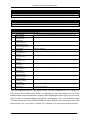
Menu and functions
Functions available in the menu and submenu are explained below.
Fig.3: Menu
2011/04/19
www.ever.eu
9
Instruction manual for Powerline RT
INFORMATION SCREEN
Function
Displays the current working mode, messages about warnings and errors
MENU 1.- STATUS
Function
Displays input and output values (voltages, frequency, load...)
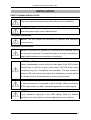
MENU 2.- LOGGING
Function
Displays five most recent events (errors, warnings...)
1
2
3
4
5
6
7
8
9
10
11
12
13
14
15
EPO RELEASE
BATT. ERROR
CALL SERVICE
OVERLOAD
CHECK OUTPUT
BYPASS OVERLOAD
OUTPUT UNPROTECT.
FAN ERROR
CHARGER
TOO HIGH VOLT.
DC BUS
TOO HIGH VOLT.
DC BUS
TOO LOW VOLT.
DC BUS
UNSTABLE
INVERTER
TOO HIGH VOLT.
INTERVERT
TOO LOW VOLT.
SHORT CIRCUIT
CHECK OUTPUT
PHASE ERROR
CHECK AC INPUT
OVERHEAT
REDUCE TEMP.
NO EVENTS
UPS stopped working, because EPO was activated (remote power supply off)
Battery error detected
Inverter overload detected (grid power or backup mode)
Overload detected when the device is in the bypass mode.
Fan failure detected
The charger supplies too high voltage (internal error)
DC voltage in the DC bus is too high (internal error)
DC voltage in the DC bus is too low (internal error)
DC voltage in the DC bus is unstable (internal error)
The inverter supplies too high voltage (internal error)
The inverter supplies too low voltage (internal error)
Inverter short circuit (internal error)
Reverse input lead sequence detected
Device overheated
No events in the register
The LCD displays shows five most recent events. They are numbered from 1 to 5, where 1 is
most recent, and 5 oldest event. Event 1 is displayed as first, and events from 2 to 5 are
displayed when the forward button is pushed. After displaying the event type, the next screen
tells you when it occurred relative to the device's working time. This is not a calendar date.
The time follows the format: DDDD:HH:MM:SS, where DDDD is the consecutive day of the
device's work, HH – hours, MM – minutes, SS – seconds. The next screen is the next event.
2011/04/19
www.ever.eu
10
Instruction manual for Powerline RT
MENU 3.- CONTROL
Submenu
Function
3.1
BATTERY TEST
After selecting this option, the battery test is performed
3.2
MANUAL BYPASS
UPS switching to the bypass mode and back
3.3
CONTROLLABLE OUTLET 1
Activation/deactivation of output group 1 (first group of controlled output sockets)
3.4
CONTROLLABLE OUTLET 2
Activation/deactivation of output group 2 (second group of controlled output
sockets)
MENU 4.- SETUP
Submenu
Function
Language selection (English, Spanish, Italian, French, Polish, Portuguese,
4.1
LANGUAGE
4.2
ACUSTIC ALARM
Sound alarm activation/deactivation (buzzer)
4.3
OUTPUT VOLTAGE
Selection of rated output voltage (200 V, 208 V, 220 V, 230 V or 240 V)
4.4
OUTPUT FREQUENCY
4.5.
4.6
4.7
German)
Selection of rated output frequency: 50 or 60 Hz (only in the frequency conversion
mode)
FREQUENCY
Activation/deactivation of frequency conversion mode (UPS must be in the standby
CONVERTER
mode)
CONTROLLABLE OUTLET
Selection of the battery charging level (75%, 50%, 25% or 0%) below which output
1 LEVEL
1 (first group of controlled output sockets) is deactivated automatically
CONTROLLABLE OUTLET
Selection of the battery charging level (75%, 50%, 25% or 0%) below which output
2 LEVEL
2 (second group of controlled output sockets) is deactivated automatically
4.8
COLD START
Activation/deactivation of cold start function (start without grid power supply)
4.9
AUTO RE-START
4.10
ECO MODE
4.11
SITE WIRING FAULT
4.12
AUTO BATTERY TEST
4.13
Activation/deactivation of automatic restart function (automatic start after the
autonomy time has lapsed, when the grid power supply resumes).
ECO mode activation/deactivation
Phase detection function activation/deactivation (detection of incorrect input lead
sequence)
Selection of the automatic battery test frequency (every day, every week, every
month...)
PRE-ALARM LEVEL
Selection of the battery charging level (75%, 50%, 25% or 0%) below which
SELECTION
Battery low signal is activated
MENU 5.- ABOUT
Function
Displays rated power of the UPS, software version and UPS working time
2011/04/19
www.ever.eu
11
Instruction manual for Powerline RT
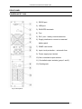
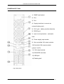
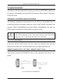
REAR PANEL
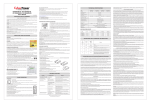
POWERLINE RT 1000
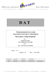
1) RS232 port
2) USB port
3) ROO/EPO terminals
4) Fan
5) RJ11 port – battery module detection
6) Supply interface to connect an external
battery pack
7) SNMP card socket
8) Input circuit protection – automatic fuse
9) Power supply input socket
10) Non-controlled output sockets
11) Controlled output sockets (group 1 and 2)
12) Earthing bolt
Fig.4: Rear panel
2011/04/19
www.ever.eu
12
Instruction manual for Powerline RT
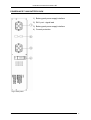
POWERLINE RT 2000
1)
SNMP card socket
2)
Fan
3)
Supply interface to connect an external
battery pack
4)
RJ11 port – battery module detection
5)
RS232 port
6)
Input circuit protection – automatic fuse
7)
Power supply input socket
8)
Non-controlled output sockets
9)
Controlled output sockets (group 1 and 2)
10) ROO/EPO terminals
11) USB port
12) Earthing bolt
Fig.5: Rear panel
2011/04/19
www.ever.eu
13
Instruction manual for Powerline RT
POWERLINE RT 3000
1) SNMP card socket
2) Fan
3) Fan
4) Supply interface to connect an
external battery pack
5) RJ11 port – battery module detection
6) RS232 port
7) Input circuit protection – automatic
fuse
8) Power supply input socket
9) Non-controlled 16A output sockets
10) Controlled 10A output sockets
(group 1 and 2)
11) 16A output sockets
12) ROO/EPO terminals
13) USB port
14) Earthing bolt
Fig.6: Rear panel
2011/04/19
www.ever.eu
14
Instruction manual for Powerline RT
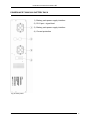
POWERLINE RT 1000 BATTERY PACK
1) Battery pack power supply interface
2) RJ11 port - signal lead
3) Battery pack power supply interface
4) Current protection
Fig.7: Rear panel
2011/04/19
www.ever.eu
15
Instruction manual for Powerline RT
POWERLINE RT 2000/3000 BATTERY PACK
1) Battery pack power supply interface
2) RJ11 port - signal lead
3) Battery pack power supply interface
4) Current protection
Fig. 8: Rear panel
2011/04/19
www.ever.eu
16
Instruction manual for Powerline RT
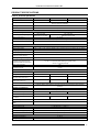
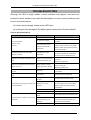
PRODUCT SPECIFICATIONS
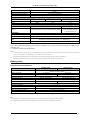
Table 3. Technical parameters
PARAMETERS / MODEL
Output power
1)
POWERLINE RT 1000
POWERLINE RT 2000
POWERLINE RT 3000
1000 VA / 800 W
2000 VA / 1600 W
3000 VA / 2400 W
Casing
Rack / Tower
(Rack Kit optionally available)
Topology
Double conversion VFI
Intended application
Backup for IT devices
INPUT
Rated input voltage
Input voltage operating range
200 - 240 VAC
120 – 275 VAC
(depending on the load)
Rated input frequency
140 – 275 VAC
(depending on the load)
50 / 60 Hz
Input frequency operating range
40 / 70 Hz (input-output synchronisation range: 50 / 60 Hz ± 5%
Power factor
0.99 (batteries charged)
OUTPUT
Voltage waveform
Rated output voltage
Sine
200 (*) / 208 (*) / 220 / 230 VAC (default) / 240 V (configured using user software and LCD display)
Voltage regulation
2%
Ouput frequency
50 / 60 Hz ± 0.5 % (same as for the input or selected in the frequency conversion mode)
Harmonic distortion (THDV)
(linear/non-linear receiver)
≤4%/≤6%
Switching time (grid-backup-grid)
0 ms
Overload range (network power
mode for the load having PF=0.8)
< 110 % warning
111-135 %: 12 seconds (UPS switching to bypass mode)
> 135 %: 1.5 second (UPS off)
Short circuit protection
Yes
GREENPOWER function
activation threshold
< 45 W
BATTERIES
Type
Configuration
Support time with internal batteries
only (100% / 80% / 50% Pmax)
Support time with battery modul
(100% / 80% / 50% Pmax)
Sealed, maintenance-free, lead-acid (VRLA)
1 x 3 x 9 Ah
1 x 6 x 9 Ah
1 x 6 x 9 Ah
7 / 10 / 17,5 min
7 / 10 / 17,5 min
3 / 5 / 10,5 min
27 / 35 / 60 min
27 / 35 / 60 min
17,5 / 22 / 38 min
Advanced battery control
Battery management
Yes
Automatic battery pack detection, automatic autonomy time calculation, deep discharge
protection
GENERAL INFORMATION
Bypass mode
Grid mode efficiency
Yes (automatic)
86%
ECO mode efficiency
Maximum noise level at a distance
of 1 metre
Variable fan speed
Option to connect external battery
packs
88%
90%
> 93%
41 dB
47 dB
47 dB
Yes
Yes (maximum 4 pcs)
CONNECTION
Communication ports
Communication socket
1 x DB9 (RS 232), 1 x USB (**)
1 x socket for SNMP / TCP-IP / Web interface or for voltage-less contact card
Remote power supply off (EPO)
Yes (EPO contact)
Remote on/off
Yes (ROO contact)
ENVIRONMENT
Operating temperature 2)
Storage temperature
2011/04/19
0 ÷ 40 ºC
-25 ÷ 50 ºC (without batteries)
www.ever.eu
17
Instruction manual for Powerline RT
-15 ÷ 40 ºC (with batteries)
Altitude (above sea level)
3)
0 - 3000 m
Relative humidity when working
< 95 % (without condensation)
Relative humidity during storage
< 95 % (without condensation)
MECHANICAL PARAMETERS
Dimensions W x H x D
438 x 86 (2U) x 483 mm
438 x 86 (2U) x 658 mm
Rack cabinet deepth
438 x 86 (2U) x 658 mm
≤ 800 mm
Weight
18.5 kg
30.5 kg
31 kg
CONNECTIONS
Input
Output
1 x IEC320 C14 (10 A)
1 x IEC320 C20 (16 A)
6 x IEC320 C13 (10 A), of which 3 are controlled (2 groups)
6 x IEC320 C13 (10 A), of which
3 are controlled (2 groups)
1 x IEC320 C19 (16 A)
STANDARDS
CE mark
Yes
Safety
EMC
EN 62040-1, EN 60950 (RD)
IEC62040-2 C2, IEC61000-3-2, IEC61000-4-2, IEC61000-4-3, IEC61000-4-4, IEC61000-4-5
IEC61000-4-6, IEC61000-4-8, IEC61000-4-11, IEC61000-2-2
Efficiency
EN62040-3
Note: The manufacturer reserves the right to change the abovementioned parameters without notice.
(*) For 200V output rated voltage, the output power is reduced by 20%. For 208 V output rated voltage, the output power is
reduced by 10%.
(**) The ports cannot be used simultaneously.
Notes:
1)
For normal operation of the battery back-up the load connected to its output should not exceed 80% of value indicated in the table. Reserve power is essential to
ensure continuous operation of connected devices in case of momentary rushes in load current.
2)
Continued exposure of the battery back-up to the temperature of the surrounding exceeding +25°C will shorten the life of batteries.
3)
If the altitude above sea level increases beyond the provided limit the permitted load power of the batter back-up decreases.
Battery packs
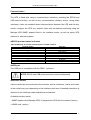
Table 4 Technical parameters
PARAMETERS / MODEL
BATTERY PACK
POWERLINE RT 1000
Rack / Tower
(Rack Kit optionally available)
Casing
Battery configuration
Protection
BATTERY PACK
POWERLINE RT 2000/3000
2 x 3 x 9 Ah
2 x 6 x 9 Ah
70 A / 80 VDC fuse
70 A / 80 VDC fuse
MECHANICAL PARAMETERS
Dimensions W x H x D
438 x 86 (2U) x 438 mm
Rack cabinet deepth
Weight
438 x 86 (2U) x 657 mm
≤ 800 mm
32 kg
52 kg
ENVIRONMENT
Operating temperature 1)
Storage temperature
Altitude (above sea level)
0 ÷ 40 ºC
-15 ÷ 40 ºC
0-3000 m
Relative humidity when working
< 95% (without condensation)
Relative humidity during storage
< 95% (without condensation)
Note: The manufacturer reserves the right to change the abovementioned parameters without notice.
Note:
1)
Continued exposure of the battery back-up to the temperature of the surrounding exceeding +25°C will s horten the life of batteries.
2)
If the altitude above sea level increases beyond the provided limit the permitted load power of the batter back-up decreases.
2011/04/19
www.ever.eu
18
Instruction manual for Powerline RT
Communication
The UPS is fitted with various communication interfaces, including the RS232 and
USB serial interface, as well as the communication interface socket. Using those
interfaces, users can establish direct communication between the UPS and the duty
server, configure the UPS as a network client with centralised monitoring using the
Manage UPS SNMP adapter fitted in the interface socket, as well as report UPS
statuses to external systems.
RS232 port and status indication
Table 5. Matching of contacts and description of DB-9 interface:
Terminal number
4
2
3
5
1
6
7
8
9
Definition
Not connected
RXD (input)
TXD (output)
GND
Battery low
Grid power parameters out of range
Bypass mode
SUM alert
Grid power parameters correct
USB port
The USB port is compatible with the USB 1.1 protocol
NOTE: RS232 and USB ports cannot be used simultaneously
Interface socket
Various cards can be connected to the interface socket. Interfaces, marks and codes
in the socket may vary depending on the interface card used. A detailed description is
attached to the interface cards available as accessories.
Available interface cards:
- SNMP adapter card (Manage UPS) to integrate the UPS with the network (option)
- AS400 card. (option)
2011/04/19
www.ever.eu
19
Instruction manual for Powerline RT
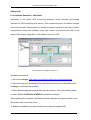
Winpower
Free software download – WinPower
WinPower is the latest UPS monitoring software, which ensures user-friendly
interface for UPS monitoring and control. This exceptional piece of software ensures
safe and automatic disconnection of multiple-computer systems in the case of power
supply failure. Using this software, users can monitor and control each UPS in the
same LAN network, regardless of the distance from the UPS.
Fig. 9:Winpower manager, version 1.0
Installation procedure:
1. Go to the webpage: http://www.ups-software-download.com/winpower.htm.
2. Select the required operating system and follow the instruction described on the
webpage to download the software.
3. When downloading the required files from the Internet, enter the following serial
number: 511C1-01220-0100-478DF2A to install the software.
After restarting the computer, WinPower software appears as a green socket icon in
the system tray, next to the clock.
4. Software installation can also be performed using the supplied CD.
2011/04/19
www.ever.eu
20
Instruction manual for Powerline RT
INSTALLATION
SAFETY DURING INSTALLATION
You must read the following safety information prior to installation!
NOTE! The UPS is completely disconnected from the power grid only
when the power supply cord is disconnected.
● Installation personnel
NOTE! The UPS should be connected by qualified and authorised
personnel only.
● Installation environment
NOTE! This product is intended for commercial and industrial use in
the second environment. To prevent disruptions, it may be necessary to
apply additional preventive measures or limitations.
NOTE! The UPS must not be installed or operated whenever water
vapour condensation occurs, which can take place if the UPS is taken
directly from a cold into a warm environment. The UPS must remain
completely dry prior to installation and operation. The time needed to
adapt to the new environment before the installation proceeds should
be at least 2 hours. Otherwise there is a risk of electrocution!
NOTE! Do not install the UPS in damp environments, next to sources
or heat or whenever it is exposed to direct sunlight. Make sure that the
UPS is kept away from water, flammable gases and corrosion agents.
NOTE! The device should be installed in well-ventilated places. Do not
cover ventilation openings in the UPS casing, keep the relevant
distances from other objects to ensure appropriate air circulations.
2011/04/19
www.ever.eu
21
Instruction manual for Powerline RT
● Cabling and earthing
NOTE! The installation and cable laying should proceed in compliance
with local laws and regulations.
NOTE! The UPS must be earthed. Prior to connecting power supply
cables to the electric system terminal on the premises, make sure that
the earthing connection is reliable. If external UPS battery packs are
connected, the main equipotential connection with the main UPS unit is
provided by the packs' power supply cables.
NOTE! The installation must enable disconnection from the grid power
supply pointe .g. through circuit breakers.
NOTE! In order to ensure that receivers can be disconnected from the
UPS at any time, emergency breaker should be installed between the
UPS output terminals and receivers. To enhance your safety, this can
be an RCD device.
● Battery
NOTE! When serially connecting several battery packs, adhere to the
"same voltage, same type" rule.
2011/04/19
www.ever.eu
22
Instruction manual for Powerline RT
UNPACKING AND CONTROL
After unpacking, check the contents of the package. The package should include:
CONTENTS OF THE PACKAGES
The packages contain:
a) UPS POWERLINE RT 1000, 2000:
- UPS unit,
- 2 sets of tower bases for vertical installation,
- 1 x power supply cord - CEE7/7 - IEC 320 C13, 10A,
- 3 x power supply cord IEC C13 - IEC C14 10A,
- 1 x USB cable,
- 1 x RS232 cable,
- CD with WinPower software,
- warranty card,
- operation manual.
b) UPS POWERLINE RT 3000:
- UPS unit,
- 2 sets of tower bases for vertical installation,
- 1 x power supply cord CEE 7/7 - IEC 320 C19, 16A,
- 2 x power supply cord IEC C13 - IEC C14 10A,
- 1 x power supply cord IEC C19 - IEC C20 16A,
- 1 x USB cable,
- 1 x RS232 cable,
- CD with WinPower software,
- warranty card,
- operation manual.
c) Rack Kit set for UPS/battery pack Rack-type installation (optional)
- set of items for Rack-type installation:
- 2 front braces for rack-type UPS installation and the required assembly tools,
- 2 slides for rack-type UPS installation (along with and angles and screws),
- printed, pictorial instruction manual for UPS/battery pack installation in the rack, and
LCD panel rotation-to-level instruction.
2011/04/19
www.ever.eu
23
Instruction manual for Powerline RT
d) SNMP card:
- SNMP card,
- 1 x RJ cable - RS232,
- CD with software,
- warranty card,
e) POWERLINE RT 1000 & 2000/3000 battery pack:
- 1 battery pack,
- 1 power connection cable,
- 1 battery pack detection cable for automatic detection of connected packs (RJ11),
- 2 sets of tower bases for vertical installation,
- binding element to join a battery pack to another battery pack or UPS,
- warranty card.
Inspect the UPS and battery pack visually to make sure there it was not damaged in
transport.
INSTALLATION
The UPS and battery packs can be installed in a rack with depth up to 800 mm. For
rack-type installation, the Rack Kit assembly set is necessary (optional accessories).
The kit contains an instruction manual and a description of how to change the LCD
panel’s position. In the standard version, the UPS is provided as a tower version
(vertical).
2011/04/19
www.ever.eu
24
Instruction manual for Powerline RT
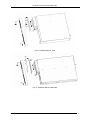
UPS and external battery pack vertical installation
1) Install two sets of tower bases supplied with the UPS and place the device
between the bases as shown on the pictures.
Fig.10: Vertical installation of the UPS
The UPS unit can be mounted in horizontal position. For the necessary information,
see User manual – quick start included in the product packaging.
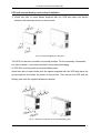
2) UPS Plus mounting with an external battery pack
Install two sets of tower bases with the spacer supplied with the UPS and place the
device between the bases as shown on the picture. Then secure the UPS and the
battery pack with the supplied plates and screws.
Fig.11: UPS Plus connection to an external battery pack
2011/04/19
www.ever.eu
25
Instruction manual for Powerline RT
POWER SUPPLY CONNECTION
Connecting an external battery pack
WARNING! Prior to connecting a battery pack to the UPS, circuit
protection of the pack must be in "OFF". After establishing the electric
connection with the UPS, the protection should be switched to "ON".
NOTE: Each battery pack comes with two battery connections. The first pack is
connected to the UPS with a cable supplied with the UPS set. Each subsequent
battery pack is connected to the previous pack using with the battery pack cable.
External battery packs (if used) should be connected to the UPS prior to its
connection to the power grid.
Follow the procedure below to connect external battery packs:
1.Set battery pack circuit protection (in each pack) to "OFF"
2.Make the connection between the pack and the UPS with the cable supplied.
3.Connect another battery pack to the already connected pack.
4.Make a "chain" of battery packs until you connect the last pack.
5.Connect the battery pack detection cable between the RJ11 port on the UPS rear
panel and the RJ11 port on the back panel of the first battery pack.
6.Connect the module detection cable between one RJ11 port on the back panel of
the first pack with one RJ11 port on the back panel of another pack.
7.Make a "chain" of battery packs using battery pack detection cables until you
connect the last pack.
8.Set battery pack circuit protection (in each pack) to "ON"
When all external battery packs are connected, make the necessary power supply
output/input connections as described below.
2011/04/19
www.ever.eu
26
Instruction manual for Powerline RT
UPS power connection
1.Connect the input power supply cord to the AC input.
NOTE: Batteries are being charged from the moment when the input power supply is
provided.
2.Connect a receiver to the UPS. It is recommended that key devices should be
connected to the main outputs, and less important ones to the controlled outputs.
NOTE: You can select disconnection threshold for controlled output
sockets using the control panel. This helps to save energy for toppriority receivers.
3. To start the UPS and external battery packs when all the connections are made,
following the instructions in the subsequent chapter (operation).
OPERATION
NOTE: UPS intended to provide backup for IT devices.
SAFE OPERATION INSTRUCTIONS
NOTE: You must read the following safety information prior to operation
of the device!
● Warnings about operation
NOTE! The UPS is completely disconnected from the power grid only
when the power supply cord is disconnected.
NOTE: Never disconnect the earthing cable at the UPS device or on
terminals of the building wiring, because this will remove the earthing
connection used to protect the UPS system and all receivers connected
to it.
2011/04/19
www.ever.eu
27
Instruction manual for Powerline RT
NOTE: UPS output sockets may be live even when the UPS system is
not connected to the power grid.
NOTE: Prevent the ingress of liquids and foreign bodies into the UPS.
NOTE: In case of electrocution or fire threat, immediately disconnect
the UPS from the power supply line and set circuit protection of the
battery packs to "OFF".
NOTE: UPS output sockets are live when the power switch on the front
panel is in "ON" position (On/Off LED is lit).
NOTE! As required by the standards, the cords may not be longer than,
respectively: output cords – 10 metres, communication cables - 3
metres, battery pack power cables – 3 metres.
STARTING THE UPS
Initial UPS start procedure
1) When using the UPS for the first time, make sure that power from the grid is
connected, and then press and hold the On/Off button until you hear a beep.
2) The UPS will respond with several sound messages, and the GRID MODE
message, along with the UPS load indication will appear on the LCD. The
connected receivers are power-supplied.
2011/04/19
www.ever.eu
28
Instruction manual for Powerline RT
Regular UPS start procedure
1) Press and hold the On/Off button until you hear a beep.
2) The UPS will respond with several sound messages, and LED’s will light up.
3) If AC grid is connected, the green LED (1) on the UPS lights up. GRID MODE
message will appear on the LCD, which means output sockets are powersupplied.
4) If there is no input power (green LED is not on), and the cold start function is on,
the backup mode LED will light up on the UPS, indicating that the device is
drawing power from the battery. BACKUP MODE message will appear on the
LCD along with the expected autonomous supply time.
NOTE: If the OVERLOAD message is displayed on the panel, this
means that too many devices are connected to the UPS. If only one
device is connected to the UPS and OVERLOAD appears on the
display, then the power demand of the receiver exceeds the UPS
power supply range, and a UPS with greater rated power must be
used.
NOTE: If the UPS does not respond as described above, go to chapter
5 ("Troubleshooting").
BYPASS MODE PROCEDURES
In order to set the device to "bypass" mode, go to menu 3 (CONTROL) and then
submenu BYPASS SWITCH, and select "SWITCH TO BYPASS", or press the
confirm button, keeping it pressed for six seconds. Follow the same procedure for the
UPS to return to the grid mode, this time selecting SWITCH TO GRID. If the UPS is
in the standby or frequency conversion mode, switching to the bypass mode is not
possible.
2011/04/19
www.ever.eu
29
Instruction manual for Powerline RT
ECO MODE PROCEDURE
If the device is off, but connected to the grid, go to menu 4 (SETTINGS), and then to
the submenu ECO MODE and select ECO ON. After the UPS is started, it will launch
in the ECO mode.
FREQUENCY CONVERTER MODE PROCEDURE
The frequency converter can be switched on if the UPS is in the standby mode. To
activate the frequency conversion mode, go to menu 4 (SETTINGS), and then to the
submenu FREQ. CONVERSION and select FREQ. CONVERSION ON. After the
UPS is started, it will launch in the frequency conversion mode.
NOTE: In the frequency conversion mode, the available supply power
of the UPS is reduced by 50%. This means that only 50% of the UPS'
rated power can be used when the device is in this mode.
UPS STOP PROCEDURE
Press and hold the On/Off button until the it goes into standby mode and then
disconnect the power line. The UPS will disconnect all outputs and switch off.
REMOTE POWER SUPPLY OFF (EPO) / REMOTE ON/OFF (ROO)
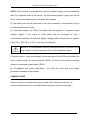
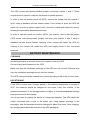
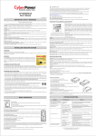
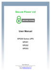
Three-output connector for EPO/ROO circuits is on the rear panel of the device - see
picture.
ROO
EPO
Fig.12: Remote UPS on/off diagrams
2011/04/19
www.ever.eu
30
Instruction manual for Powerline RT
The UPS comes with factory-installed jumper connecting outputs 1 and 2. These
outputs must be joined in order for the device to operate properly.
In order to use the remote power off (EPO), remove the jumper and join outputs 1
and 2 using a standard volt-free closed contact. If the contact is open, the UPS will
switch off. In order to resume regular work, close the contact and restart the device,
following the procedure described previously.
In order to use the remote on function (RPO), join outputs 1 and 2 with the jumper
(UPS comes with factory-made jumper) and then joint outputs 2 and 3 using a
standard volt-free closed contact. Opening of the contact will switch the UPS off.
Closing of the contact will restart the UPS and supply power to the connected
receivers.
BATTERY MAINTENANCE
CLEANING
Scrubbing powders or solvents must not be used to clean the UPS.
Do not let any liquid ingress into the UPS.
Make sure that the ventilation openings on the UPS are not covered. Remove dust
from the ventilation openings using a vacuum cleaner.
The UPS casing should be cleaned from outside by wiping it with a dry or moist cloth.
UPS STORAGE
If the UPS is stored over a longer period in the ambient temperature in excess of
25ºC, the batteries should be charged for five hours, every four months. If the
ambient temperature in the storage location is higher, it is recommended that storage
time is shortened to two months.
You do not need to unpack the device to charge the batteries. The UPS should be
simply connected with a cord to the power grid, using special openings in the
packaging, and the batteries should be charged for about five hours. After charging,
the charging date should be entered on the UPS packaging.
2011/04/19
www.ever.eu
31
Instruction manual for Powerline RT
BATTERY TESTING
Thee UPS does not require maintenance by the user, however the batteries should
be periodically inspected.
The UPS automatically performs battery auto test once a week. If a problem appears,
the error LED will light up, or an error message will be displayed on the LCD.
Testing frequency can be changed using the control panel or user software. The
option BATTERY TEST DAILY, WEEKLY, MONTHLY, or OFF should be selected from
the submenu AUTOMATIC BATTERY TEST in the SETTINGS menu.
BATTERY REPLACEMENT
NOTE: Receivers connected to the UPS will not be protected against
input power loss during the operation.
External UPS battery pack replacement
The UPS does not require user maintenance, although maintenance according to
IEEE Recommended Practice for Maintenance, Testing, and Replacement of ValveRegulated Lead-Acid (VRLA) Batteries for Stationary Applications (IEEE Standard
1188-1996) is recommended. If the batteries run out, personnel trained on battery
operation should replace them.
The replacement is performed in the maintenance access area.
The battery maintenance should be ensured or supervised by personnel familiar with
battery operation, using the appropriate precautions.
During the replacement, the same type and quantity of batteries, or battery sets,
should be used.
2011/04/19
www.ever.eu
32
Instruction manual for Powerline RT
WARNING! Protect the batteries against fire – explosive!
WARNING! Do not open the batteries, and protect them against
damage. Spilt electrolyte is harmful to the eyes and skin, and could be
toxic.
WARNING! The battery set may pose a risk of electrocution.
WARNING! The battery is not isolated from power supply lines.
Dangerous voltage may appear between the battery terminals and
earthing point.
When working with batteries, the following precautions should be applied:
Take off watches, rings and other metal objects.
Use tools with insulated handles.
Put on rubber gloves and footwear.
Do not place tools or metal parts on batteries.
Power source should be disconnected prior to connecting or disconnecting battery
terminals.
A typical battery lifespan is from 3 to 5 years in the ambient temperature of 25ºC.
Nevertheless, battery lifespan also depends on the frequency and duration of grid
power failures and periods in which the batteries are discharged.
After the end of the battery's useful life, follow the battery replacement procedure.
The battery test should be performed periodically (every 6 to 12 months) in order to
check general battery performance.
In order to replace the internal batteries, manually set the UPS to the bypass mode
(see "Bypass mode procedures" and follow the sequence of actions shown on the
pictures:
2011/04/19
www.ever.eu
33
Instruction manual for Powerline RT
Fig.13: POWERLINE RT 1000
Fig.14: POWERLINE RT 2000/3000
2011/04/19
www.ever.eu
34
Instruction manual for Powerline RT
Battery disposal
Disposal/recycling of the UPS and/or batteries should be handled by a company
certified in disposal/recycling. Used rechargeable batteries are classified as
"dangerous toxic waste" and, under the law, must be disposed of or recycled by an
authorised recycling centre.
The manufacturer's service centre is fully equipped to handle such batteries in
compliance with the law and paying utmost attention to environmental protection.
Contact the customer service representative to arrange for battery maintenance
and/or replacement.
After the battery replacement, the certified disposing/recycling company must
dispose of/recycle the used batteries.
The appropriate utilisation of used electric and electronic equipment helps
protect human health and the natural environment against the negative effects
brought about by the presence of hazardous materials and components, and
the improper storage and processing of such equipment.
Act of 29 July 2005, on Waste Electric and Electronic Equipment, Article 22.1, Point
1.2.
The crossed out waste container symbol means that, in the
European Union, a used product should be handed over to a
special waste handling outlet. This concerns both the device itself,
and all the accessories marked with this symbol. Such products should not be
disposed of together with unsorted municipal waste.
2011/04/19
www.ever.eu
35
Instruction manual for Powerline RT
TROUBLESHOOTING
Although the UPS is highly reliable, certain problems may appear, and users are
advised to check whether they match the descriptions of most common problems and
how to solve them below:
a) is there correct supply voltage at the UPS input,
b) Is the input fuse damaged? Did battery pack fuses switch off automatically?
Table 6. Recommendations
Problem
No recommendation
Possible cause
Corrective measures
Grid power switched off
Switch on the grid power switch
No grid power voltage
No alarm sound
(UPS off)
Burnt input fuse or circuit
protection automatically
switched off
Overload message on the LCD display
Overload error: UPS is
Receiver connected
overloaded
A battery error message is displayed on the
Battery error detected during
LCD.
the automatic battery test
Battery error LED flashes/long sound signal
Battery lifespan is ending,
approx. every hour
battery duty time is reduced
An internal error message is displayed on
the LCD.
Overheat error message is displayed on the
LCD.
UPS error
Overheating
Battery pack protection is set
to "OFF"
Order grid power inspection from a qualified
electrician
Replace with a fuse of the same type, or
switch on circuit protection. If the problem
persists, contact the appropriate customer
service representative
Check the value of the current supplied by
the receivers. Reduce the number of the
connected receivers. Restart the UPS
Inspect if the battery connector is properly
connected.
Replace the battery pack
Switch off the alarm by pressing the ESC
button for 3 seconds
Replace the battery pack
Contact the authorised customer service
representative
Reduce the ambient temperature
Set battery pack protection to "ON"
Charge up the batteries and test their duty
Autonomous power supply time shorter than
Batteries are not fully
time in the backup mode. If the problem
in the specifications
charged
persists, contact the customer service
representative.
Batteries are damaged
Contact the customer service representative
The charger is damaged
Contact the customer service representative
Incorrect serial connection
cable
Check whether the correct cable was used
Communication error between the UPS and
Computer interface is used
Check whether other software/service has
a computer
by another process or is
access to the computer interface, try to
damaged.
select another serial interface
Disruptions on data cable
Relay the cable/reinstall the cabling
2011/04/19
www.ever.eu
36
Instruction manual for Powerline RT
TRANSPORT AND STORAGE
The UPS should be transported only in the original packaging.
The UPS should be stored in a ventilated and dry place.
LAWS, REGULATIONS AND THE WARRANTY
DECLARATION OF CONFORMITY
The UPS structure complies with the provisions of the pertinent standards.
WARRANTY
The warranty for the device constitutes a separate document enclosed with the
product. This document must meet all the formal requirements (e.g. the following field
should be filled in: manufacturing number, model/type, date of sale, and stamp of the
seller).
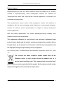
The manufacturer has made every effort to ensure that the offered products are free
of defects in materials and workmanship. The liability of the company under the
warranty is limited to the repair or replacement of products containing such defects.
The method for removal of defects shall be determined by the manufacturer. The
warranty shall not cover those appliances with mechanical damage that were
improperly maintained or used, or that were modified in any way by the user.
EVER Sp. z o.o. does not provide any guarantees or warranties, including the
guarantees of fitness for sale or for any specific purpose, other than what is set out in
the warranty card.
EVER Sp. z o.o. shall not be liable for any direct, indirect, extraordinary, coincidental,
or consequential losses resulting from the use of the power supply unit, even if the
possible occurrence of such losses has been notified. The company shall not be held
liable for any costs, such as the loss of profits or earnings, equipment, equipment
usage, software, data, costs of replacement products, claims of third parties, or for
any other costs whatsoever.
Information on warranty and post-warranty repairs as well as other maintenance
services, as well as this instruction in English, Czech and Slovak can be obtained on
our website at www.ever.eu.
2011/04/19
www.ever.eu
37