1
Operation/Reference Guide
UDM-0808-SIG
8x8 Signature Series Multi-Format Distribution Hub
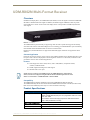
UDM-RX02N
Multi-Format Receiver
UDM-ABB-8-SIG
Signature Series Audio Breakout Box
Universal Distribution Matrix
Last Revised: 11/15/2010
AMX Limited Warranty and Disclaimer
This Limited Warranty and Disclaimer extends only to products purchased directly from AMX or an AMX Authorized Partner which
include AMX Dealers, Distributors, VIP’s or other AMX authorized entity.
AMX warrants its products to be free of defects in material and workmanship under normal use for three (3) years from the date of
purchase, with the following exceptions:
•
Electroluminescent and LCD Control Panels are warranted for three (3) years, except for the display and touch overlay components are warranted for a period of one (1) year.
•
Disk drive mechanisms, pan/tilt heads, power supplies, and MX Series products are warranted for a period of one (1) year.
•
AMX lighting products are guaranteed to switch on and off any load that is properly connected to our lighting products, as long
as the AMX lighting products are under warranty. AMX also guarantees the control of dimmable loads that are properly connected to our lighting products. The dimming performance or quality there of is not guaranteed, impart due to the random combinations of dimmers, lamps and ballasts or transformers.
•
AMX software is warranted for a period of ninety (90) days.
•
Batteries and incandescent lamps are not covered under the warranty.
•
AMX AutoPatch Epica, Modula, Modula Series4, Modula CatPro Series and 8Y-3000 product models will be free of defects in
materials and manufacture at the time of sale and will remain in good working order for a period of three (3) years following the
date of the original sales invoice from AMX. The three-year warranty period will be extended to the life of the product (Limited
Lifetime Warranty) if the warranty card is filled out by the dealer and/or end user and returned to AMX so that AMX receives it
within thirty (30) days of the installation of equipment but no later than six (6) months from original AMX sales invoice date. The
life of the product extends until five (5) years after AMX ceases manufacturing the product model. The Limited Lifetime Warranty
applies to products in their original installation only. If a product is moved to a different installation, the Limited Lifetime Warranty
will no longer apply, and the product warranty will instead be the three (3) year Limited Warranty.
All products returned to AMX require a Return Material Authorization (RMA) number. The RMA number is obtained from the AMX
RMA Department. The RMA number must be clearly marked on the outside of each box. The RMA is valid for a 30-day period. After
the 30-day period the RMA will be cancelled. Any shipments received not consistent with the RMA, or after the RMA is cancelled, will
be refused. AMX is not responsible for products returned without a valid RMA number.
AMX is not liable for any damages caused by its products or for the failure of its products to perform. This includes any lost profits, lost
savings, incidental damages, or consequential damages. AMX is not liable for any claim made by a third party or by an AMX Authorized Partner for a third party.
This Limited Warranty does not apply to (a) any AMX product that has been modified, altered or repaired by an unauthorized agent or
improperly transported, stored, installed, used, or maintained; (b) damage caused by acts of nature, including flood, erosion, or earthquake; (c) damage caused by a sustained low or high voltage situation or by a low or high voltage disturbance, including brownouts,
sags, spikes, or power outages; or (d) damage caused by war, vandalism, theft, depletion, or obsolescence.
This limitation of liability applies whether damages are sought, or a claim is made, under this warranty or as a tort claim (including
negligence and strict product liability), a contract claim, or any other claim. This limitation of liability cannot be waived or amended by
any person. This limitation of liability will be effective even if AMX or an authorized representative of AMX has been advised of the
possibility of any such damages. This limitation of liability, however, will not apply to claims for personal injury.
Some states do not allow a limitation of how long an implied warranty last. Some states do not allow the limitation or exclusion of incidental or consequential damages for consumer products. In such states, the limitation or exclusion of the Limited Warranty may not
apply. This Limited Warranty gives the owner specific legal rights. The owner may also have other rights that vary from state to state.
The owner is advised to consult applicable state laws for full determination of rights.
EXCEPT AS EXPRESSLY SET FORTH IN THIS WARRANTY, AMX MAKES NO OTHER WARRANTIES, EXPRESSED OR
IMPLIED, INCLUDING ANY IMPLIED WARRANTIES OF MERCHANTABILITY OR FITNESS FOR A PARTICULAR PURPOSE. AMX
EXPRESSLY DISCLAIMS ALL WARRANTIES NOT STATED IN THIS LIMITED WARRANTY. ANY IMPLIED WARRANTIES THAT
MAY BE IMPOSED BY LAW ARE LIMITED TO THE TERMS OF THIS LIMITED WARRANTY. EXCEPT AS OTHERWISE LIMITED
BY APPLICABLE LAW, AMX RESERVES THE RIGHT TO MODIFY OR DISCONTINUE DESIGNS, SPECIFICATIONS, WARRANTIES, PRICES, AND POLICIES WITHOUT NOTICE.
Table of Contents
Table of Contents
Important Safety Markings ................................................................................. a
Markings Used In This Manual .................................................................................. a
Voltage............................................................................................................................ a
Rating Label.............................................................................................................. a
Important Instructions .............................................................................................. b
Compliance ............................................................................................................... b
FCC and IEC .................................................................................................................... b
Environmental Conditions......................................................................................... b
Temperature ................................................................................................................... b
Ventilation....................................................................................................................... b
Humidity.......................................................................................................................... b
Water / Liquids................................................................................................................ b
External use ..................................................................................................................... b
UDM-0808-SIG 8x8 Signature Series Multi-Format Distribution Hub .................1
Overview .................................................................................................................. 1
Features.................................................................................................................... 1
Common Application....................................................................................................... 1
Compatibility................................................................................................................... 1
Product Specifications ............................................................................................. 2
Configuration Options .............................................................................................. 3
Rack-Mounting the UDM-0808-SIG........................................................................... 3
Ventilation....................................................................................................................... 4
UDM-0808-SIG Wiring and Connections .............................................................5
Overview .................................................................................................................. 5
UDM-0808-SIG Front Panel Components ................................................................. 5
Power Status bar............................................................................................................. 5
Status LEDs ..................................................................................................................... 5
UDM-0808-SIG Rear Panel Components................................................................... 6
Connecting UDM-RX02N Receivers to the UDM-0808-SIG ............................................. 6
UDM Output Ports (RJ45) ......................................................................................... 6
UDM Port Pinouts ........................................................................................................... 6
A/V Source Input Connectors ................................................................................... 7
VIDEO IN Connectors (HD15).......................................................................................... 7
Connecting a VGA Video Input ....................................................................................... 7
Connecting a Composite Video Input ............................................................................. 7
Connecting a Component Video Input ............................................................................ 8
UDM-0808-SIG, UDM-RX02N and UDM-ABB-8-SIG Operation /Reference Guide
i
Table of Contents
Connecting an S-Video Input........................................................................................... 8
Video Adapter Cables ..................................................................................................... 8
Audio & Video Formats/Resolutions/Distance................................................................. 8
NETWORK Port (RJ45).............................................................................................. 9
SERIAL (RJ12) Port.................................................................................................... 9
Serial Port - Default Communication Settings ............................................................... 10
DB9-to-RJ12 Adapter Cable Pinouts ............................................................................. 10
CASCADE Ports ...................................................................................................... 10
IEC Power Connector.............................................................................................. 11
Powering the UDM-0808-SIG Hub On........................................................................... 11
Powering the UDM-0808-SIG Hub Off .......................................................................... 11
UDM-0808-SIG NetLinx Programming ..............................................................13
Overview ................................................................................................................ 13
Device Numbering .................................................................................................. 13
LEVELs ................................................................................................................... 14
SEND_COMMANDs .............................................................................................. 15
"'?FWVERSIOND'" .................................................................................................................... 15
"'?TEMP'" ................................................................................................................................. 15
"'AI"' ......................................................................................................................................... 15
"'?A'" ........................................................................................................................................ 16
"'CI"' ......................................................................................................................................... 16
"'CL'" ........................................................................................................................................ 17
"'?C'" ........................................................................................................................................ 17
"'MMOFF'" ............................................................................................................................... 18
"'MMON'" ................................................................................................................................ 18
"?MM" ...................................................................................................................................... 18
"'RESET'" .................................................................................................................................. 18
"'RESETFACTORY'" .................................................................................................................. 19
"'RPUOFF'" ............................................................................................................................... 19
"'RPUON'" ................................................................................................................................ 19
"?RPU" ...................................................................................................................................... 19
"'SAI'" ....................................................................................................................................... 20
"'?SAI'" ..................................................................................................................................... 20
"'SFI'" ....................................................................................................................................... 20
"'?SFI'" ...................................................................................................................................... 21
"'SVI'" ....................................................................................................................................... 21
"'?SVI'" ..................................................................................................................................... 21
"'VI"' ......................................................................................................................................... 22
"'?V'" ........................................................................................................................................ 22
UDM-0808-SIG WebConsole ............................................................................23
Overview ................................................................................................................ 23
Determining the IP Address of the UDM-0808-SIG ................................................ 23
Bonjour (Zero-Configuration) Client .............................................................................. 23
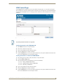
Accessing the WebConsole ........................................................................................... 24
ii
UDM-0808-SIG, UDM-RX02N and UDM-ABB-8-SIG Operation /Reference Guide
Table of Contents
Admin Menu ........................................................................................................... 24
UDM Control Page.................................................................................................. 25
Sending Commands to the UDM-0808-SIG ................................................................... 25
Sending Commands to a Connected UDM-RX02N........................................................ 25
Device Configuration Page ..................................................................................... 26
Device Configuration tab .............................................................................................. 26
Master Connection tab.................................................................................................. 26
Changing the Connection Mode ................................................................................... 27
Changing the Mode Settings ........................................................................................ 27
Authentication Settings................................................................................................. 27
Security Settings ..................................................................................................... 27
Enable / Disable Security Settings ............................................................................... 28
Login Information.......................................................................................................... 28
Logging Into the Configuration Manager (With Security Enabled)................................ 28
IP Settings............................................................................................................... 29
Port Settings........................................................................................................... 30
Clock Manager........................................................................................................ 30
Clock Manager - Mode Manager................................................................................... 31
Clock Manager - Daylight Savings ................................................................................. 32
Clock Manager - NIST Servers ....................................................................................... 33
UDM-0808-SIG Firmware Upgrades .................................................................35
Overview ................................................................................................................ 35
Before You Start ..................................................................................................... 35
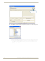
Sending a Firmware (*.KIT) File To the UDM-0808-SIG ................................................. 35
Firmware Readme.TXT .................................................................................................. 37
Additional Documentation ............................................................................................ 37
UDM-RX02N Multi-Format Receiver .................................................................39
Overview ................................................................................................................ 39
Common Application..................................................................................................... 39
Features ........................................................................................................................ 39
Compatibility................................................................................................................. 39
Product Specifications ........................................................................................... 39
Configuration Options ............................................................................................ 40
UDM-RX02N Wiring and Connections ..............................................................41
Overview ................................................................................................................ 41
Power Connector .................................................................................................... 41
Powering on the UDM-RX02N ...................................................................................... 41
UDM HUB (RJ-45) Port............................................................................................ 42
Connecting the UDM-RX02N to a UDM-0808-SIG Hub................................................. 42
UDM-0808-SIG, UDM-RX02N and UDM-ABB-8-SIG Operation /Reference Guide
iii
Table of Contents
UDM Port LEDs ............................................................................................................. 42
CONTROL Connectors ............................................................................................ 43
SERIAL (RJ12) Port ........................................................................................................ 43
IR Rx (IR Receiver) Port.................................................................................................. 44
Using the UDM-RC05 for Video Compensation............................................................. 45
IR Tx (IR Transmitter) Port ............................................................................................. 45
AUDIO & VIDEO Output Connectors...................................................................... 46
CVBS (Composite) Video Output Port .......................................................................... 46
S-VIDEO Video Output Port ......................................................................................... 46
VGA Video Output Port ............................................................................................... 47
Component (Y/Pb/Pr) Video Output Port ..................................................................... 47
Video Compensation .............................................................................................. 48
UDM-RX02N NetLinx Programming .................................................................49
Overview ................................................................................................................ 49
Device Numbering .................................................................................................. 49
CHANNELs ............................................................................................................. 50
LEVELs .................................................................................................................... 50
SEND_COMMANDs ................................................................................................ 50
"'RP'" ........................................................................................................................................ 50
"'?RP'" ...................................................................................................................................... 51
"'SB'" ........................................................................................................................................ 51
"'?SB'" ...................................................................................................................................... 51
"'SD'" ........................................................................................................................................ 51
"'SKB'" ...................................................................................................................................... 51
"'SKG'" ..................................................................................................................................... 51
IR SEND_COMMANDs ............................................................................................ 52
IR CHANNELs ................................................................................................................ 52
IR SEND_COMMANDs ................................................................................................. 52
"'CAROFF'" ............................................................................................................................... 52
"'CARON'" ................................................................................................................................ 52
"'SKR'" ...................................................................................................................................... 52
"'?SK'" ...................................................................................................................................... 52
"'SS'" ........................................................................................................................................ 52
"'?SS'" ...................................................................................................................................... 52
"'CH'" ....................................................................................................................................... 53
"'CP'" ........................................................................................................................................ 53
"'CTOF'" ................................................................................................................................... 53
"'CTON'" .................................................................................................................................. 53
"'IROFF'" .................................................................................................................................. 53
"'SP'" ........................................................................................................................................ 54
"'XCH'" ..................................................................................................................................... 54
"'XCHM'" .................................................................................................................................. 54
Serial SEND_STRING............................................................................................... 55
iv
UDM-0808-SIG, UDM-RX02N and UDM-ABB-8-SIG Operation /Reference Guide
Table of Contents
Serial SEND_COMMANDs ...................................................................................... 55
"'CHARD'" .................................................................................................................................55
"'CHARDM>'" ...........................................................................................................................55
"'GET BAUD'" ...........................................................................................................................55
"'RXCLR'" ..................................................................................................................................55
"'RXOFF'" .................................................................................................................................55
Serial Control Considerations With UDM-0808 and UDM-RX02N ................................. 56
"'RXON'" ...................................................................................................................................56
"'SET BAUD'" ............................................................................................................................56
"'TXCLR'" ..................................................................................................................................56
UDM-RX02N Firmware Upgrades .....................................................................59
Overview ................................................................................................................ 59
Before You Start ..................................................................................................... 59
Sending a Firmware (*.KIT) File To the UDM-RX02N .................................................... 59
Additional Documentation ............................................................................................ 61
UDM-RX02N IR File Transfers ...........................................................................63
Overview ................................................................................................................ 63
Sending a IR Library (*.IRL) File To the UDM-RX02N .............................................. 63
Additional Documentation ............................................................................................ 65
UDM-RC05 Multi-Format IR Remote Control ....................................................67
Overview ................................................................................................................ 67
IR Codes / UDM-RC05 Pushbuttons .............................................................................. 67
Using the UDM-RC05 for Video Compensation ............................................................ 69
UDM-ABB-8-SIG Audio Breakout Box ...............................................................71
Overview ................................................................................................................ 71
Common Application..................................................................................................... 71
Features ........................................................................................................................ 71
Compatibility................................................................................................................. 71
Product Specifications ........................................................................................... 72
Connecting the UDM-ABB-8-SIG to an UDM-0808-SIG........................................... 72
Connecting Audio Outputs ........................................................................................... 73
UDM-ABB-8-SIG Configuration ............................................................................... 73
"SFI" Send Command.................................................................................................... 73
"SAI" Send Command ................................................................................................... 75
Cascading Hubs ................................................................................................77
Overview ................................................................................................................ 77
Cascade In/Out Connectors .................................................................................... 77
Cascading Guidelines.............................................................................................. 78
Maximum Number of Cascaded 0808 Hubs .................................................................. 78
Applications With a Mix of Component and VGA Inputs .............................................. 78
UDM-0808-SIG, UDM-RX02N and UDM-ABB-8-SIG Operation /Reference Guide
v
Table of Contents
Signage Applications..................................................................................................... 78
Maximizing Performance Of Cascaded UDM-0808-SIG Hubs........................................ 79
Configuring a UDM-0808-SIG Hub For Cascading......................................................... 79
Using the UDM-ABB-8-SIG Audio Breakout Box ........................................................... 79
Cascading Two Hubs - Cable Connections..................................................................... 81
Cascading up to Four Hubs - Cable Connections........................................................... 81
Configuring the Source Hub ................................................................................... 82
"MMON" Send Command............................................................................................. 82
Configuring the Hub as a Target Hub ..................................................................... 83
"MMOFF" Send Command............................................................................................ 83
Specifying Cascaded Ports...................................................................................... 83
"SVI" Send Command ................................................................................................... 83
Cascading Hubs - Code Examples........................................................................... 84
Appendix ..........................................................................................................85
Ascii / Hex Conversion ............................................................................................ 85
vi
UDM-0808-SIG, UDM-RX02N and UDM-ABB-8-SIG Operation /Reference Guide
Important Safety Markings
Important Safety Markings
Markings Used In This Manual
The following symbols are used on the UDM hardware and throughout this Installation Guide to advise you of
important instructions. All maintenance must be carried out by an AMX trained and qualified installer.
Voltage
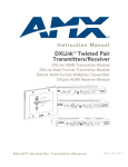
This symbol (FIG. 1) warns the presence of a voltage of sufficient magnitude to cause a severe or fatal electric
shock. Follow the appropriate instructions carefully to avoid the risk of injury.
FIG. 1 Voltage symbol
There are NO user serviceable parts within the UDM Hub.
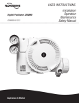
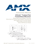
Rating Label
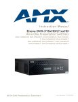
The rating label (FIG. 2), containing important safety information, is found on the underside of the UDM Hub.
Symbols used on this label are explained below;
The UDM Hub is powered from a suitable 24 VDC supply.
FCC (Federal Communications Commission) Standards;
TESTED TO COMPLY
WITH FCC STANDARDS
FOR HOME OR OFFICE USE
This device complies with part 15 of the FCC rules.
Operation is subject to the following two conditions:
(1) This device may not cause harmful interference.
(2) This device must accept any interference received
including interference that may cause undesirable operation.
Conforms to particular European Directives.
FIG. 2 Rating Label
UDM-0808-SIG, UDM-RX02N and UDM-ABB-8-SIG Operation /Reference Guide
a
Important Safety Markings
Important Instructions
This symbol, used within this manual, indicates an important instruction for the
correct and safe installation, operation or maintenance of your UDM Hub.
Failure to comply with such instruction may result in injury to person or damage to the
UDM hardware.
Compliance
FCC and IEC
Compliance with FCC and IEC standards are found within the rating label; see above.
Environmental Conditions
The criteria on this page must be observed for the installation of the UDM-0808-SIG.
Temperature
DO NOT install or operate the UDM Hub in an area where the ambient temperature exceeds 35ºC (95ºF) or
falls below 5ºC (35ºF).
Ventilation
DO NOT obstruct the side ventilation grilles during operation as this will restrict the airflow and may cause
the main board to overheat.
The UDM Hub is fitted with two cooling fans. These draw cool air through the right side ventilation grille and
expel warm air through the grilles on the left side ventilation grilles.
Humidity
DO NOT install or operate the UDM Hub in an area in which the ambient relative humidity exceeds 85% or an
area that is prone to condensation.
Water / Liquids
DO NOT install or operate the UDM Hub near water or in a location which may be prone to water seepage,
dripping or splashing.
DO NOT place objects containing liquids on the appliance.
The Hub is not waterproof.
External use
DO NOT operate the UDM Hub externally.
b
UDM-0808-SIG, UDM-RX02N and UDM-ABB-8-SIG Operation /Reference Guide
UDM-0808-SIG 8x8 Signature Series Multi-Format Distribution Hub
UDM-0808-SIG 8x8 Signature Series
Multi-Format Distribution Hub
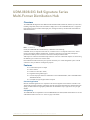
Overview
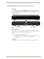
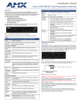
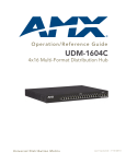
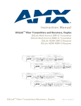
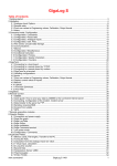
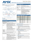
The UDM-0808-SIG Signature Series Multi-Format Distribution Hub (FG1402-01) delivers any video source,
including Component, RGB, VGA and S-Video to display devices. The UDM-0808-SIG (FIG. 1) supports 8
high-resolution input ports and 8 UDM output ports, and supports delivery of bidirectional serial and IR to/
from remote devices.
FIG. 1 UDM-0808-SIG
In total, the UDM-0808-SIG can distribute any combination of the following:
8 RGBHV sources, 8 Component video sources, 8 S-Video sources or 8 Composite video sources. Source
inputs to the UDM are industry standard VGA, Composite, Component or S-Video feed, and output is
presented as an RJ45 port for connection to Cat5/5e/6/7 twisted-pair Ethernet cable.
Video inputs are connected via the HD15 Input connector on the rear of the UDM. Adapters are used to bring
the different types of video source into the UDM.
Each UDM has an Ethernet network port to provide connectivity to a central management system. A Serial
connection is also provided for CLI diagnostic purposes.
Features
8 multi-format inputs x 8 outputs
Native NetLinx
End device control (IR + Serial)
Digital and Analog audio support
Cascade output ports allow A/V distribution to other UDM-0808 Hubs, and to UDM-ABB-8-SIG
Audio Breakout Box.
Cascadable to support higher number of outputs
Common Application
Ideal for residential applications as a companion to the NI-3101 Signature Series NetLinx Controller or the
Tango Audio Controller as all three components share the same elegant finish and mirror matched showroom
styling. An ideal solution for high quality whole home AV distribution of up to eight sources to up to eight
displays.
Compatibility
The UDM-0808-SIG is compatible for use with UDM-RX02N (FG-1402-20) Multi-Format Receivers. See the
UDM-RX02N Multi-Format Receiver section on page 39 for details.
UDM-0808-SIG, UDM-RX02N and UDM-ABB-8-SIG Operation /Reference Guide
1
UDM-0808-SIG 8x8 Signature Series Multi-Format Distribution Hub
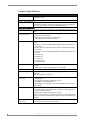
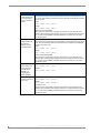
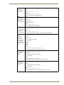
Product Specifications
UDM-0808-SIG Specifications
Power Requirements:
• 3 PIN IEC, 100 to 240Vac 50/60Hz
• Dissipation: 130W
Front Panel Components
LEDs
• Power Status bar - Blue light bar on front panel indicates unit is powered.
• Status LEDs - Eight blue LEDs light to indicate which of the eight outputs are
currently routing video to a connected UDM-RX02N Receiver.
Rear Panel Components
UDM Output Ports (1-8): Eight RJ45 ports provide connectivity to up to 8 UDM-RX02N receivers via Cat5/
5e/6/7.
A/V Source Input
Connectors (A-H):
Eight sets of Input connections for up to 8 A/V inputs with the following connectors:
• Video (see Video Inputs below)
• Analog audio Left / Right (see Audio Inputs below)
• SPDIF digital audio (see Audio Inputs below)
Video Inputs:
HD15 female connector supports the following formats:
• VGA
• Component - requires an UDM-HD15RCA3 Breakout Cable (FG-HD15RCA3,
not included)
• S-Video - requires an UDM-SVID01 HD15 to SVideo cable (FG-UDM-SVID01,
not included)
• Composite - requires an UDM-HD15RCA3 Breakout Cable (FG-HD15RCA3, not
included)
• Max Video Input:
• 8 x RGBHV (or)
• 8 x S-Video (or)
• 8 x component (or)
• 24 composite inputs
Audio Inputs:
• Analog Audio In - RCA female analog audio connectors (white = Left, red =
Right).
• SPDIF Audio In - RCA female digital audio connector (black).
NETWORK Port:
RJ45 Ethernet port provides 100 BaseT network connectivity.
SERIAL Port:
RJ12 port allows an administrator to receive debugging and diagnostic information
via RS232.
Note: Serial Interface: 115200, 8, N, 1
CASCADE Ports
(1-4 / 5-8):
• Cascade Out and In ports send and receive cascaded A/V signals to other UDM0808-SIG Hubs.
• The Cascade Out ports also provide audio-only to an
UDM-ABB-8-SIG Audio Breakout Box.
Note: Depending on the application, up to four UDM-0808-SIG Hubs can be cascaded together.
IEC Power Connector:
Universal switch-mode power supply.
• As a Class 1 appliance the Hub should be connected to a mains supply with a
protective earthing connection.
• On/Off switch is located beside the power connector.
Note: The rating label found on the bottom left of the rear panel (beneath the IEC
connector) contains important information applicable to the Hub’s installation environment.
Operating
Environment:
2
• 35°F to 95°F (5°C to 35°C)
• Max. relative humidity - 85% (non-condensing)
UDM-0808-SIG, UDM-RX02N and UDM-ABB-8-SIG Operation /Reference Guide
UDM-0808-SIG 8x8 Signature Series Multi-Format Distribution Hub
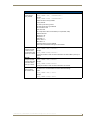
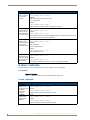
UDM-0808-SIG Specifications (Cont.)
Dimensions:
• 3.5" x 19" x 12 1/2" (889 mm x 440 mm x 320 mm)
• 2 RU
Weight:
13.6 lbs. (6.16 kg)
Certifications:
• CE
• FCC part 15 Class A
Included Accessories:
• IEC power cord
• 19" mounting brackets
• UDM-RC05 Multi-Format IR Remote Control (FG1402-70)
• IR03 External Infrared Receiver Module (FG-IR03)
Note: No A/V interface cables supplied.
Other AMX Equipment:
• HD15 to S-Video Cable (FG-UDM-SVID01)
• HD15 to 3x RCA Breakout Cable (FG-HD15RCA3)
• UDM-RX02N Multi-Format Receiver (FG-1402-20)
• UDM-ABB-8-SIG Audio Breakout Box (FG1402-60)
• IR01 IR Emitter Module (FG-IR01)
• UDM-EXP-02 Cascade Cable (FG1402-71)
• RS-232 DB-9/RJ-12 connection cable (FG-RS01)
• 6' Ethernet Crossover Cable
Configuration Options
Use NetLinx SEND_COMMANDs to configure and control the UDM-0808-SIG. Refer to the
UDM-0808-SIG NetLinx Programming section on page 13 for programming details.
The UDM-0808-SIG WebConsole can be used to configure master connection, networking, and
time settings. Refer to the UDM-0808-SIG WebConsole section on page 23 for details.
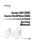
Rack-Mounting the UDM-0808-SIG
The UDM-0808-SIG occupies two rack spaces in a standard 19" equipment rack. Rack mounting brackets and
screws are located in the accessories box supplied with the UDM-0808-SIG.
Exercise extreme care when lifting or moving the Hub within the rack to avoid injury. It
is recommended that you seek the assistance of another person when rack mounting
the UDM-0808-SIG.
1. Remove the aluminum feet from the bottom of the Hub.
2. Attach one rack mounting bracket to each side of the UDM-0808-SIG using two M4 screws for each
bracket (FIG. 2).
Rack-Mounting Brackets
FIG. 2 Attach the mounting brackets to each side of the Hub (2 brackets per side)
To prevent injury the Hub must be securely attached to the rack in accordance with
the installation instructions.
Always use the special rack mount brackets supplied and high quality fixing screws to
ensure the Hub is installed in the rack correctly.
3. Place the UDM-0808-SIG in the equipment rack and hold steady.
UDM-0808-SIG, UDM-RX02N and UDM-ABB-8-SIG Operation /Reference Guide
3
UDM-0808-SIG 8x8 Signature Series Multi-Format Distribution Hub
4. Two Mounting holes are located on each side of the UDM-0808-SIG. Screw the Hub into the rack using
the Mounting holes (FIG. 3).
Mounting holes (2 per side)
FIG. 3 Screw the Hub into the rack using the fixing holes
DO NOT stand other units directly on top of the Hub when it is rack mounted, as this
will place excessive strain on the mounting brackets.
Ventilation
ALWAYS ensure that the rack enclosure is adequately ventilated.
Sufficient airflow must be achieved (by convection or forced-air cooling) to satisfy the ventilation
requirements of all the items of equipment installed within the rack.
4
UDM-0808-SIG, UDM-RX02N and UDM-ABB-8-SIG Operation /Reference Guide
UDM-0808-SIG Wiring and Connections
UDM-0808-SIG Wiring and Connections
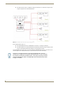
Overview
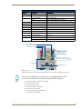
The system diagram in FIG. 4 illustrates a basic installation using the UDM-0808-SIG Hub, UDM-RX02N
receivers, UDM-ABB-8-SIG audio breakout box, and attached display and audio playback devices:
Video Projector Screen
1500VG Touch Panel
NI-3101-SIG
NetLinx Master
Plasma
UDM-0808-SIG
LCD
UDM-RX02N
UDM-RX02N
VCR
TV
DVD
UDM-RX02N
UDM-RX02N
UDM-ABB-8-SIG
PC
Laptop
Ethernet
Serial
Audio/Video
Cat5
IR Control
SWT
Internet
Tango Audio Controller
C-Series In-Ceiling Speakers
(Speaker Wire Technology)
FIG. 4 UDM-0808-SIG System Diagram
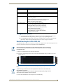
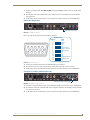
UDM-0808-SIG Front Panel Components
The components on the front panel of the UDM-0808-SIG are described below (FIG. 5).
Power Status
8 Output Port Status LEDs
(front)
FIG. 5 UDM-0808-SIG - Front Panel Components
Power Status bar
The blue light bar on front panel indicates that the unit is powered.
Status LEDs
The eight blue LEDs on the front panel light to indicate which of the eight outputs are currently routing video
to a connected UDM-RX02N Receiver.
UDM-0808-SIG, UDM-RX02N and UDM-ABB-8-SIG Operation /Reference Guide
5
UDM-0808-SIG Wiring and Connections
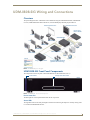
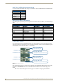
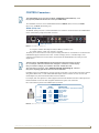
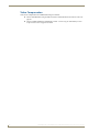
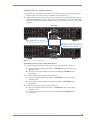
UDM-0808-SIG Rear Panel Components
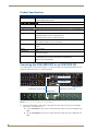
FIG. 6 shows the components on the rear panel of the UDM-0808-SIG:
Serial port (RJ12)
UDM OUTPUT Ports 1-8 (RJ45)
ETHERNET port (RJ45)
Input connections
Input connections
Cascade In/Out
Power connector/switch
FIG. 6 UDM-0808-SIG - Rear Panel Components
Connecting UDM-RX02N Receivers to the UDM-0808-SIG
1. Connect a standard Cat 5/5e/6/7cable to a UDM OUTPUT port (1-8) on the UDM-0808-SIG.
2. Connect the other end of the Cat 5/5e/6/7 cable to the “UDM Hub” port on the UDM-RX02N Receiver.
3. When the power is switched on 2 LEDs will be visible at the Hub port – Amber (phantom power enabled)
and Green (UDM receiver connected to Hub port).
UDM Output Ports (RJ45)
The eight RJ45 ports on the rear panel of the UDM-0808 (see "UDM Output Ports 1-8" in FIG. 6 above)
provide connectivity to a UDM-RX02 Multi-Format Receiver.
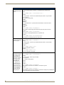
UDM Port Pinouts
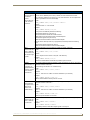
The following table provides detailed pinout information for the UDM port:
A/V Transmission Over UTP (UDM)
RJ45
Pin #
568A
Termination
Color
A/V Signals
568B
Termination
Pair #
RGB
YPbPr
CVBS
S-Video
1
3
Red +
Y+
CVBS S1 +
Y+
Color
Pair #
2
3
Red -
Y-
CVBS S1 -
Y-
2
3
2
Blue +
Pr +
CVBS S3 +
C+
3
2
4
1
Green +
Pb +
CVBS S2 +
1
5
1
Green -
Pb -
CVBS S2 -
1
6
2
Blue -
Pr -
CVBS S3 -
C-
7
4
Audio, Data, Power +
Audio, Data, Power +
Audio, Data, Power +
Audio, Data, Power +
4
8
4
Audio, Data, Power -
Audio, Data, Power -
Audio, Data, Power -
Audio, Data, Power -
4
3
An incorrectly terminated cable will result in the following scenarios:
Incorrectly Terminated Cable Results
RJ45
Pin #
6
RGBHV Video
Component Video
Composite Video
SVideo
UDM Audio & Data RX
Green LED
1-2
No RED
No Y
No Video 1
No Y
On With Audio & Data RX
3-6
No BLUE
No Pr
No Video 2
No C
On With Audio & Data RX
4-5
No GREEN
No Pb
No Video 3
NONE
On With Audio & Data RX
7-8
NONE
NONE
NONE
NONE
Always OFF
UDM-0808-SIG, UDM-RX02N and UDM-ABB-8-SIG Operation /Reference Guide
UDM-0808-SIG Wiring and Connections
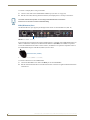
A/V Source Input Connectors
There are eight sets of input connectors to the rear panel of the UDM-0808-SIG, labelled A - H (FIG. 7).
Digital Audio Input (SPDIF)
RCA Audio Inputs (L/R)
Video Input (female HD15)
FIG. 7 A/V Source Input connectors (A and B shown)
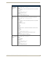
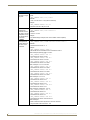
VIDEO IN Connectors (HD15)
FIG. 8 provides the pin layout for the VIDEO IN HD15 Connectors:
HD15 Pinouts
5
4
10
15
3
9
14
2
8
13
1
7
12
6
11
Input Pin
1
2
3
4
5
6
7
8
9
10
11
12
13
14
15
VGA
Component
Red
Pr
Green
Y
Blue
Pb
n/c
n/c
Ground
n/c
Red - Ground
Pr - Ground
Green - Ground Y - Ground
Blue - Ground
Pb - Ground
n/c
n/c
Ground
n/c
n/c
n/c
n/c
n/c
Horz. Synch
n/c
Vert. Synch
n/c
n/c
n/c
S-Video
Luminance
n/c
Chrominance
n/c
n/c
Luminance - Ground
n/c
Chrominance - Ground
n/c
n/c
n/c
n/c
n/c
n/c
n/c
Composite
CVBS1
CVBS2
CVBS3
n/c
n/c
CVBS1 - Ground
CVBS2 - Ground
CVBS3 - Ground
n/c
n/c
n/c
n/c
n/c
n/c
n/c
FIG. 8 VIDEO IN HD15 Connector
Connecting a VGA Video Input
1. Connect one end of a VGA cable to the source device’s VGA output port.
2. Attach the other end of the cable to the appropriate VIDEO IN connection (A-H) on the UDM-0808-SIG.
3. Connect the source audio to the analog (RCA) audio jacks, or digital (SPDIF) Input connector.
Ensure the UDM Hub port to which the RX02N Receiver is attached is configured
correctly (via NetLinx programming). Also ensure the correct Audio Type (Analog L/R,
S/PDIF, or None) is selected for the relevant input.
Connecting a Composite Video Input
1. Connect the UDM-HD15RCA3 Breakout Cable (FG-HD15RCA3, not included) to the source device’s
Composite output ports:
A1 = red RCA
2. Attach the other end of the cable to the appropriate VIDEO IN connector (A-H) on the UDM-0808-SIG.
3. Connect the source audio to the analog (RCA) audio jacks, or digital (SPDIF) Input connector.
UDM-0808-SIG, UDM-RX02N and UDM-ABB-8-SIG Operation /Reference Guide
7
UDM-0808-SIG Wiring and Connections
Connecting a Component Video Input
1. Connect the UDM-HD15RCA3 Breakout Cable (FG-HD15RCA3, not included) to the video source
device’s Component video output connectors (Red, Green and Blue).
2. Attach the other end of the cable to the appropriate VIDEO IN connector (A-H) on the UDM.
3. Connect the source audio to the analog (RCA) audio jacks, or digital (SPDIF) Input connector.
Connecting an S-Video Input
1. Connect the UDM-SVID01 HD15 to SVideo Cable (FG-UDM-SVID01, not included) to the video
source’s S-Video connection.
2. Attach the other end of the cable to the appropriate VIDEO IN connector (A-H) on the UDM.
3. Connect source audio to the analog (RCA) audio jacks, or digital (SPDIF) Input connector.
Video Adapter Cables
The following adapter cables are available from AMX, to allow connecting various video input types to the
UDM-0102:
Video Adapter Cables
Name
FG #
Description
UDM-HD15RCA3 FG-HD15RCA3
UDM-SVID01
HD-15 to 3x RCA Breakout Cable
FG-UDM-SVID01 HD-15 to S-Video Cable Breakout Cable
Audio & Video Formats/Resolutions/Distance
The following table provides recommended maximum distances for cable runs, based on video class type at
various resolutions:
Audio & Video Formats/Resolutions/Distance
Class
Format
Name
UDM-RX02N
Composite/S-Video
720 x 480
NTSC
300 m / 1000’
720 x 576
PAL
300 m / 1000’
720 x 480
480p
300 m / 1000’
720 x 576
576p
300 m / 1000’
1280 x 720
720p
300 m / 1000’
1920 x 1080
1080i
300 m / 1000’
1920 x 1080
1080p
300 m / 1000’
640 x 480
VGA
300 m / 1000’ *
800 x 600
SVGA
300 m / 1000’ *
1024 x 768
XGA
300 m / 1000’ *
1280 x 1024
SXGA
300 m / 1000’ *
1600 x 1200
UXGA
140 m / 460’
1920 x 1080
HD
140 m / 460’
Component
RGBHV
* When using VGA modes with audio enabled, the
maximum cable distance is approximately 200 m / 650’ (UDM-RX02N).
It is important to note that the maximum distances indicated above are not absolute, but are recommended
distances that have been tested to deliver video at the specified resolutions, without significant signal
degradation. In particular, lower resolutions (640 x 480, 720 x 480 and 800 x 600) can often be delivered
significantly further than what is indicated in the table.
Several factors affect the overall quality of the displayed video, including the quality of the twisted pair cable
and connectors used, the nature of the video image itself, as well as the particulars of the installation and how
the video is displayed and viewed.
8
UDM-0808-SIG, UDM-RX02N and UDM-ABB-8-SIG Operation /Reference Guide
UDM-0808-SIG Wiring and Connections
Two major factors that can affect the quality of signal transmission include:
Cable Distance: Long distance cable runs (in excess of 300 meters/1000 feet) are subject to
resistance and capacitance losses which can negatively impact the quality of the image.
Skew: "Skew" represents the slight delay that results from the variation in wiring lengths for each
of the twisted pairs. The effects of skew on A/V signals increases with cable length. Excessive skew
can adversely affect video image quality, especially at long cable lengths and high signal
resolutions.
NETWORK Port (RJ45)
The NETWORK (RJ45) port provides 10/100 BaseT network connectivity. The following table lists the
pinouts, signals, and pairing for the Network port.
Ethernet Pinouts and Signals
Pin
1
Signals
TX +
Connections
Pairing
1 --------- 1
1 --------- 2
Color
White-Orange
2
TX -
2 --------- 2
3
RX +
3 --------- 3
Orange
4
no connection
4 --------- 4
Blue
5
no connection
5 --------- 5
White-Blue
3 --------- 6
White-Green
6
RX -
6 --------- 6
Green
7
no connection
7 --------- 7
White-Brown
8
no connection
8 --------- 8
Brown
FIG. 9 diagrams the pinouts and signals for the Network RJ45 connector and cable.
FIG. 9 RJ45 wiring diagram
By default, the UDM-0808-SIG is configured for DHCP. Refer to the IP Settings section on page 29 for
details.
Consult the Network Administrator for correct cabling from the UDM-0808-SIG onto
the network. For remote connectivity, the Firewall may have to be configured to open
port 2008 for remote connectivity over UDP
SERIAL (RJ12) Port
Connecting the SERIAL port on the UDM-0808-SIG is not an essential step in the
installation process.
The SERIAL (RJ12) port on the rear panel is available for diagnostic and troubleshooting purposes. The Serial
port on the UDM-0808-SIG is an RJ12 connector, and requires a DB9-to-RJ12 adapter cable (FG-RS01, not
included) to connect to a PC for Terminal control.
UDM-0808-SIG, UDM-RX02N and UDM-ABB-8-SIG Operation /Reference Guide
9
UDM-0808-SIG Wiring and Connections
Serial Port - Default Communication Settings
Use hyper terminal with default serial settings to communicate with the UDM-0808-SIG (and UDM-RX02N):
Default Serial Settings
Baud Rate:
115200
Data Bits:
8
Parity:
None
Stop Bits:
1
Flow Control:
None
DB9-to-RJ12 Adapter Cable Pinouts
The following table provides the pinout configuration for the DB9-to-RJ12 (FG-RS01, not included) adapter
cable:
DB9-to-RJ12 Adapter Cable Pinouts
DB9 connector
Function
Abbreviation
Pin 1
Not used
NC
RJ12 connector
Pin 2
Transmit Data
TD or TX or TXD
Pin 2
Pin 3
Receive Data
RD or RX or RXD
Pin 3
Pin 4
Data Set Ready
DSR
Pin 1
Pin 5
Signal Ground
GND
Pin 4, 5
Pin 6
Data Terminal Ready
DTR
Pin 6
Pin 7
Not Used
NC
Pin 8
Not Used
NC
Pin 9
Not Used
NC
CASCADE Ports
The CASCADE ports allow UDM-0808-SIG Hubs to be chained together to increase the number of outputs
which can be delivered to the end points. The CASCADE IN and OUT connectors on the UDM Hubs require a
UDM-EXP-02 Cascade Cable (FG-1402-71 - not included).
From source UDM Hub
(CASCADE OUT port)
CASCADE 5-8 IN
To another UDM Hub or
CASCADE 5-8 OUT
CASCADE 1-4 IN
UDM-ABB-8-SIG (CASCADE IN port)
From source UDM Hub
(CASCADE OUT port)
CASCADE 1-4 OUT
To another UDM Hub or
UDM-ABB-8-SIG (CASCADE IN port)
FIG. 10 Cascade 5-8, 1-4 Ports
The CASCADE (Out) ports can also be used to send audio to the UDM-ABB-8-SIG Signature Series Audio
Breakout Box (FG1402-60). Refer to the UDM-ABB-8-SIG Audio Breakout Box section on page 71 for
details.
Refer to the Cascading Hubs section on page 77 for details on configuring cascaded Hubs.
10
UDM-0808-SIG, UDM-RX02N and UDM-ABB-8-SIG Operation /Reference Guide
UDM-0808-SIG Wiring and Connections
IEC Power Connector
The UDM-0808-SIG uses a universal switch-mode power supply, which operates from 90-264V AC,
50/60Hz, with a power consumption of 130W fully loaded.
The rating label found to the bottom left of the Hub, beneath the IEC connector, contains important
information applicable to the Hub's installation environment.
The Power On/Off switch is located beside the IEC power connector.
As a Class 1 appliance the UDM-0808-SIG should be connected to a wall socket with
a protective earthing connection.
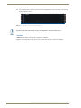
Powering the UDM-0808-SIG Hub On
1. Ensure a standard PC mains lead has been connected to the 3-pin power connection, and then connected
to a mains power source.
2. Flip the power switch down to its On (|) position.
The Power Status light bar indicates that the Hub is receiving power.
While the Hub boots, the left-most front panel LED (FIG. 11) will blink until the Hub is fully booted and
connected to a NetLinx Master. If the Hub is not configured to properly connect to a master it will continue to
blink indefinitely until the configuration is changed.
Power Status
This LED blinks to indicate that Hub is booting up and
connecting to a Master.
FIG. 11 UDM-0808-SIG - LED blinks to indicate
Powering the UDM-0808-SIG Hub Off
Where a mains plug (or appliance coupler) is used in the event of a fault, the Hub can
be disconnected from the mains by removing the lead from the IEC inlet or from the
mains socket.
It is important that the Hub is installed in such a way that this method remains readily
operable.
The user should have easy access to either the IEC inlet or the mains socket in the
event of a fault.
To turn the UDM-0808-SIG off, flip the Power switch to it’s Off (0) position.
UDM-0808-SIG, UDM-RX02N and UDM-ABB-8-SIG Operation /Reference Guide
11
UDM-0808-SIG Wiring and Connections
12
UDM-0808-SIG, UDM-RX02N and UDM-ABB-8-SIG Operation /Reference Guide
UDM-0808-SIG NetLinx Programming
UDM-0808-SIG NetLinx Programming
Overview
There are a select number of LEVELs and SEND_COMMANDs recognized by the UDM-0808-SIG. Use
NetLinx Studio to send these commands to the UDM Hub.
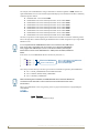
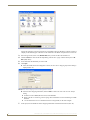
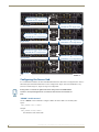
Device Numbering
By default, the Device Number assigned to the UDM-0808-SIG is 05600.
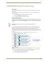
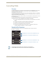
In NetLinx Studio’s online device tree, the UDM-0808-SIG is listed as a device with a single port, and each
UDM-RX02N Receiver connected to the Hub is listed as a separate device immediately following the Hub
(FIG. 12).
UDM-0808-SIG Hub, with device
number assigned to 05600 (default)
UDM-RX02N Receiver
number auto-assigned to 05601
Ports 1-3 on UDM-RX02N
(device number 05601)
UDM-RX02N Receiver
number auto-assigned to 05603
Ports 1-3 on UDM-RX02N
(device number 05603)
UDM-RX02N Receiver
number auto-assigned to 05605
Ports 1-3 on UDM-RX02N
(device number 05605)
FIG. 12 NetLinx Studio Online Tree - indicating UDM-0808-SIG hubs and connected RX02N receivers
Only UDM-RX02N units that are physically connected to the Hub will be represented
in the Online Tree.
Note that the device number for each UDM-RX02N Receiver currently connected to the Hub is automatically
designated a device number, based on the device number of the Hub to which it is connected, and the number
of the UDM Output RJ45 port on the Hub (1-8) to which it is physically connected.
UDM-0808-SIG, UDM-RX02N and UDM-ABB-8-SIG Operation /Reference Guide
13
UDM-0808-SIG NetLinx Programming
For example, if the UDM-0808-SIG is using it’s default device number assignment of 05600, and there are
eight UDM-RX02N receivers connected to all eight UDM Output ports on the Hub, then the device numbering
would be assigned as follows:
UDM-0808-SIG = device number 05600
UDM-RX02N connected to UDM Output Port #1 = device number 05601
UDM-RX02N connected to UDM Output Port #2 = device number 05602
UDM-RX02N connected to UDM Output Port #3 = device number 05603
UDM-RX02N connected to UDM Output Port #4 = device number 05604
UDM-RX02N connected to UDM Output Port #5 = device number 05605
UDM-RX02N connected to UDM Output Port #6 = device number 05606
UDM-RX02N connected to UDM Output Port #7 = device number 05607
UDM-RX02N connected to UDM Output Port #8 = device number 05608
Therefore, it important to avoid assigning device numbers that will conflict with this auto-numbering scheme.
Reserve the eight device numbers following the UDM Hub’s device number assignment for up to eight UDMRX02N receivers.
It is not required that the UDM-RX02N receivers are connected to the UDM Output
ports on the Hub in sequential order. For example, if you had three UDM-RX02N
units, plugged into UDM Outputs 2, 5 and 7, the device numbers (assuming the
default device number of the UDM-0808-SIG - 05600) would be 05602, 05605 and
05607.
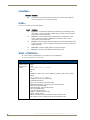
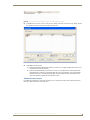
In the device tree, each UDM-RX02N Receiver shows three ports (FIG. 13)
Ports 1-3 on UDM-RX02N
(device number 06931)
Port 1 - main device port / IR Receiver
Port 2 - Serial (RS232) port
Port 3 - IR device port
FIG. 13 NetLinx Studio Online Tree - Ports 1-3 on each connected UDM-RX02N
These three ports relate directly to the three types of NetLinx commands recognized by the UDM-RX02N:
Port 1 - SEND_COMMANDS/LEVELS and Button Pushes
Port 2 - SERIAL (RS232) SEND_COMMANDS
Port 3 - IR SEND_COMMANDS
When transferring files to RX02Ns, the UDM-0808-SIG Hub to which the RX02Ns are
connected must be rebooted in order for the files to be transferred from the Hub to
the Receivers.
Refer to the UDM-RX02N NetLinx Programming section on page 49 for instructions on programming the
UDM-RX02N.
LEVELs
Level Function
33
14
Internal temperature (in deg C)
UDM-0808-SIG, UDM-RX02N and UDM-ABB-8-SIG Operation /Reference Guide
UDM-0808-SIG NetLinx Programming
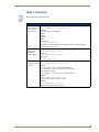
SEND_COMMANDs
All text is based on a Unicode index.
UDM-0808-SIG SEND COMMANDs
"'?FWVERSIOND'"
Syntax:
Returns the firmware
version of various
Hub components.
Variables:
SEND_COMMAND <DEV>, "'?FWVERSIOND<D#>'"
• D# = Hub component description:
"MAIN",
"PORT",
"INPUT",
"AUX",
Return Value:
"FWVERSION-<version>"
If the D and component description is omitted then the command will return the
version number of the Hub.
"'?TEMP'"
Syntax:
Returns internal
temperature in
degrees (Celsius).
Example:
SEND_COMMAND <DEV>,"'?TEMP""
SEND_COMMAND dvUDM,"'?TEMP'"
Return value:
"TEMP-<temperature>"
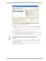
"'AI"'
Syntax:
SEND_COMMAND <DEV>,'"AI<I#>O<O#>"'
Connect audio inputs
to outputs.
Variables:
• I# = input number - initial 'I' may be omitted if desired
1-8 = Inputs A-H - a value of 0 means no input (disconnect)
• O# = output port number:
1-8 = Outputs 1-8 - a value of 0 or "ALL" means all outputs
Example 1:
SEND_COMMAND dvUDM,'"AI4O4,5,6"'
Connect input D audio to outputs 4, 5 and 6.
Example2:
SEND_COMMAND dvUDM,'"A0O1,4,5"
Disconnect audio from outputs 1,4 and 5.
UDM-0808-SIG, UDM-RX02N and UDM-ABB-8-SIG Operation /Reference Guide
15
UDM-0808-SIG NetLinx Programming
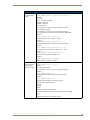
UDM-0808-SIG SEND COMMANDs (Cont.)
"'?A'"
Syntax:
Returns connection
status for audio
outputs in the Hub.
Variables:
SEND_COMMAND <DEV>, "'?A<O#>'"
• O# = output port number:
1-8 = Outputs 1-8 - a value of 0 or "ALL" means all outputs
Example 1:
SEND_COMMAND dvUDM,"'?A'"
Returns which audio inputs are connected for all outputs.
Example 2:
SEND_COMMAND dvUDM,"'?A1"
Returns which audio input is connected to output 1.
The returned string is of the form
AO#-II#
Where:
• O# is the queried output port number
• I# is the connected input number (zero if disconnected)
For example:
A6-I3
Indicates that audio output 6 was connected to input 3.
"'CI"'
Syntax:
Connect video and
audio inputs to
outputs.
Variables:
SEND_COMMAND <DEV>,'"CI<I#>O<O#>"'
• I# = input number
1-8 = Inputs A-H - a value of 0 means no input (disconnect)
• O# = output port number:
1-8 = Outputs 1-8 - a value of 0 or "ALL" means all outputs
• S# = optional sub input number (1-3) for selection of CVBS inputs
Example 1:
SEND_COMMAND dvUDM,'"CI2O4"'
Connect input B video and audio to output 4.
Example 2:
SEND_COMMAND dvUDM,'"CI3O0"
Connect input C video and audio to all outputs.
Example 3:
SEND_COMMAND dvUDM,'"C0O0"'
Disconnect all outputs from inputs.
16
UDM-0808-SIG, UDM-RX02N and UDM-ABB-8-SIG Operation /Reference Guide
UDM-0808-SIG NetLinx Programming
UDM-0808-SIG SEND COMMANDs (Cont.)
"'CL'"
Syntax:
Connects inputs to
outputs.
Variables:
SEND_COMMAND <DEV>, "'CL<L#>I<I#>O<O#>S<S#>'"
• L# = level:
"ALL" - both video and audio
"VIDEO" - video only
"AUDIO" - audio only
• I# = input number
1-8 = Inputs A-H - a value of 0 means no input (disconnect)
• O# = output port number:
1-8 = Outputs 1-8 - a value of 0 or "ALL" means all outputs
• S# = optional sub input number (1-3) for selection of CVBS inputs
Example 1:
SEND_COMMAND dvUDM,"'CLALLI3O5'"
Connects audio & video on input C to output 5.
Example 2:
SEND_COMMAND dvUDM,'"CLALLI2O4,5,6,7,8'"
Connects audio and video on input B to outputs 4 through 8.
Example 3:
SEND_COMMAND dvUDM,'"CLAUDIOI4O1,2,6,7,8'"
Connects audio only on input D to outputs 1, 2,6, 7 and 8.
Example 4:
SEND_COMMAND dvUDM,'"CLAUDIOI0O1,4,5"'
Disconnect audio source from outputs 1,4,5.
Example 5:
SEND_COMMAND dvUDM,'"CLVIDEOI2O0"
Connect video on input B to all outputs.
"'?C'"
Syntax:
Returns connection
status for video
outputs in the Hub.
Variables:
SEND_COMMAND <DEV>, "'?C<O#>'"
• O# = output port number:
1-8 = Outputs 1-8 - a value of 0 or "ALL" means all outputs
Example 1:
SEND_COMMAND dvUDM,"'?C'"
Returns which video inputs are connected for all outputs.
Example 2:
SEND_COMMAND dvUDM,"'?C1"
Returns which video input is connected to output 1
The returned strings are of the form:
• VO#-II#
• AO#-II#
Where:
• O# is the queried output port number
• I# is the connected input number (zero if disconnected), for example
V4-I2
A4-I2
Indicates that output 4 is connected to input 2.
UDM-0808-SIG, UDM-RX02N and UDM-ABB-8-SIG Operation /Reference Guide
17
UDM-0808-SIG NetLinx Programming
UDM-0808-SIG SEND COMMANDs (Cont.)
"'MMOFF'"
Configures the Hub
as a Target (Slave)
Hub in a cascaded
system.
This command configures the cascade video inputs and outputs to be correctly driven
and designates this Hub to receive audio and data clocks from a cascaded Source Hub.
This command takes effect the next time the Hub is rebooted (via the RESET command
or a power cycle).
Syntax:
SEND_COMMAND <DEV>,"'MMOFF'"
Example:
SEND_COMMAND dvUDM,"'MMOFF'"
Sets this Hub to Target Mode.
Note: If Source or Target mode is changed, then the Hub must be rebooted via the
"'RESET'" Send Command. When changing a Hub from a Target Hub back to a Source
Hub, you must send the MMON command, RESET the unit, allow it to come online,
then RESET it again.
"'MMON'"
Configures the Hub
as the Source
(Master) Hub in a
cascaded system.
There can only be one Source Hub in a chain. This command configures the cascade
video outputs to be correctly driven and designates this Hub to generate audio and data
clocks. This command takes effect the next time the Hub is rebooted (via the RESET
command or a power cycle).
Syntax:
SEND_COMMAND <DEV>,"'MMON'"
Example:
SEND_COMMAND dvUDM,"'MMON'"
Sets this Hub to Master Mode.
Note: If Source or Target mode is changed, then the Hub must be rebooted via the
"'RESET'" Send Command. When changing a Hub from a Target Hub back to a Source
Hub, you must send the MMON command, RESET the unit, allow it to come online,
then RESET it again.
"?MM"
Shows whether the
Hub is set to be a
cascade Master
(MMON) or a
cascade Target
(Slave) (MMOFF).
Syntax:
SEND_COMMAND <DEV>,"'?MM'"
Example:
SEND_COMMAND dvUDM,"'?MM'"
"'RESET'"
Syntax:
Performs a soft boot
on the Hub.
Example:
SEND_COMMAND <DEV>,"'RESET'"
SEND_COMMAND dvUDM,"'RESET'"
Reboots the Hub.
Note: If Source or Target mode is changed, then the Hub must be rebooted via the
"'RESET'" Send Command. When changing a Hub from a Target Hub back to a Source
Hub, you must send the MMON command, RESET the unit, allow it to come online,
then RESET it again.
18
UDM-0808-SIG, UDM-RX02N and UDM-ABB-8-SIG Operation /Reference Guide
UDM-0808-SIG NetLinx Programming
UDM-0808-SIG SEND COMMANDs (Cont.)
"'RESETFACTORY'" Syntax:
Resets values to
factory defaults.
SEND_COMMAND <DEV>, "'RESETFACTORY'"
Example:
SEND_COMMAND dvUDM, "'RESETFACTORY'"
Resets the Hub to factory defaults
Factory Defaults:
• All video inputs set to type VGA
• All audio inputs set to type ANALOG
• All connections reset
• RPU set to ON
• All compensation values set to default (no compensation, SD0)
Default values are:
Brightness = 48
Sharpness = 0
Red Skew = 0
Green Skew = 0
Blue Skew = 0
• IR Remote Protocol is set to RPAMX
• After reboot: All webserver settings are set to default.
"'RPUOFF'"
Syntax:
SEND_COMMAND <DEV>,"'RPUOFF'"
Configures the Hub
to clear all connecExample:
tions and status after
SEND_COMMAND dvUDM,"'RPUOFF'"
a power up or reboot.
Configures the Hub so that connections and status are cleared after a power up or
reboot.
"'RPUON'"
Configures the Hub
to restore status and
connections after a
power up or reboot.
"?RPU"
Returns whether
RPU is ON or OFF.
Syntax:
SEND_COMMAND <DEV>,"'RPUON'"
Example:
SEND_COMMAND dvUDM,"'RPUON'"
Configures the Hub so that connections and status are restored.
If RPU is ON, the Hub restores connections and settings internally. If RPU is OFF, the
Hub relies on the connected Master to restore status and settings.
Syntax:
SEND_COMMAND <DEV>,"'?RPU'"
Example:
SEND_COMMAND dvUDM,"'?RPU'"
UDM-0808-SIG, UDM-RX02N and UDM-ABB-8-SIG Operation /Reference Guide
19
UDM-0808-SIG NetLinx Programming
UDM-0808-SIG SEND COMMANDs (Cont.)
"'SAI'"
Configures an audio
input.
Configures an audio input to accept signals of a certain type, and sets the source as
either the local (back panel) connection or cascaded from an upstream Hub.
Syntax:
SEND_COMMAND <DEV>, "'SAI<I#>T<T#>C<C#>'"
Variables:
• I# = input number - a value of zero indicates all inputs, initial 'I' may be omitted
1-8 = Inputs A-H
• T# = type of incoming audio:
"NONE"
"ANALOG"
"DIGITAL"
• C# = Cascade selector - if present assume CASCADE, if not assume LOCAL
"LOCAL"
"CASCADE"
Example 1:
SEND_COMMAND dvUDM,"'SAI2TANALOG'"
Sets input B to accept analog stereo signals from the back panel connectors.
Example 2:
SEND_COMMAND dvUDM,"'SA3TDIGITALC'"
Sets input C to accept digital audio from an upstream Hub.
Example 3:
SEND_COMMAND dvUDM,'"SAI7DIGITALCLOCAL"'
Sets input G to accept digital audio from back panel.
"'?SAI'"
Syntax:
SEND_COMMAND <DEV>, "'?SAI<I#>'"
Returns configuration
of audio inputs.
Variables:
• I# = input number - a value of zero indicates all inputs, initial 'I' may be omitted
1-8 = Inputs A-H
Example 1:
SEND_COMMAND dvUDM,"'?SA3'"
Returns configuration of input C.
Example 2:
SEND_COMMAND dvUDM,"'?SA'"
Returns configuration of all inputs.
"'SFI'"
Determines whether
the cascade audio
output follows the
local input or follows
whichever input is
connected to the
associated port.
For example, the
cascade output for
input A can be the
signal on the local
input A connector, or
it can be whatever
signal is switched
through to port 1.
20
Syntax:
SEND_COMMAND <DEV>, "'SFI<I#>F<F#>'"
Variables:
• I# = input number - initial 'I' may be omitted
1-8 = Inputs A-H
• F# = Output to follow selector
"INPUT"
"PORT"
Example 1:
SEND_COMMAND dvUDM,"'SFI2FINPUT'"
Sets expansion channel 2 to be whatever is connected to input B.
Example 2:
SEND_COMMAND dvUDM,"'SF2FPORT'"
Sets expansion channel 2 to be whatever is connected to output port 2 (it follows port
2 as it is switched from one input to another).
UDM-0808-SIG, UDM-RX02N and UDM-ABB-8-SIG Operation /Reference Guide
UDM-0808-SIG NetLinx Programming
UDM-0808-SIG SEND COMMANDs (Cont.)
"'?SFI'"
Syntax:
Returns cascade
configuration of
inputs.
Variables:
SEND_COMMAND <DEV>, "'?SF<I#>'"
• I# = input number - a value of zero indicates all inputs, initial 'I' may be omitted
1-8 = Inputs A-H
Example 1:
SEND_COMMAND dvUDM,"'?SF2'"
Returns configuration of input B.
Example 2:
SEND_COMMAND dvUDM,"'?SF'"
Returns cascade configuration of all inputs.
"'SVI'"
Configures a video
input.
Configures a video input to accept signals of a certain type, and sets the source as
either the local (back panel) connection or cascaded from an upstream Hub.
Syntax:
SEND_COMMAND <DEV>, "'SVI<I#>T<T#>C<C#>'"
Variables:
• I# = input number - a value of zero indicates all inputs, initial 'I' may be omitted
1-8 = Inputs A-H
0 = All inputs
• T# = type of incoming video:
"VGA"
"CVBS"
"SVIDEO"
"COMP"
• C# = Cascade selector - if present assume CASCADE, if not assume LOCAL
"LOCAL"
"CASCADE"
Example 1:
SEND_COMMAND dvUDM,"'SV2TVGA'"
Sets input B to accept VGA signals from the back panel connectors.
Example 2:
SEND_COMMAND dvUDM,"'SVI0TCVBSC'"
Sets all inputs to CVBS from the cascade inputs.
"'?SVI'"
Syntax:
SEND_COMMAND <DEV>, "'?SVI<I#>'"
Returns configuration
of inputs.
Variables:
• I# = input number
1-8 = Inputs A-H
Example 1:
SEND_COMMAND dvUDM,"'?SV2'"
Returns configuration of input B.
Example 2:
SEND_COMMAND dvUDM,"'?SV'"
Returns configuration of all inputs.
UDM-0808-SIG, UDM-RX02N and UDM-ABB-8-SIG Operation /Reference Guide
21
UDM-0808-SIG NetLinx Programming
UDM-0808-SIG SEND COMMANDs (Cont.)
"'VI"'
Syntax:
Connect video inputs
to outputs.
Variables:
SEND_COMMAND <DEV>,'"VI<I#>O<O#>S<S#>"'
• I# = input number
1-8 = Inputs A-H - a value of 0 means no input (disconnect)
• O# = output port number:
1-8 = Outputs 1-8 - a value of 0 or "ALL" means all outputs
• S# = optional sub input number (1-3) for selection of CVBS inputs
Example 1:
SEND_COMMAND dvUDM,'"VI6O4"'
Connect input F video to output 4.
Example2:
SEND_COMMAND dvUDM,'"VI3O0"
Connect input C video to all outputs.
"'?V'"
Syntax:
Returns connection
status for video
outputs in the Hub.
Variables:
SEND_COMMAND <DEV>, "'?V<O#>'"
• O# = output port number:
1-8 = Outputs 1-8 - a value of 0 or "ALL" means all outputs
Example 1:
SEND_COMMAND dvUDM,"'?V'"
Returns which video inputs are connected for all outputs.
Example 2:
SEND_COMMAND dvUDM,"'?V3,4"
Returns which video input is connected to output 3 and which video input is connected
to output 4.
The returned string is of the form:
VO#-II#
Where:
• O# is the queried output port number
• I# is the connected input number (zero if disconnected)
For example
V6-I3
Indicates that output 6 is connected to input 3.
22
UDM-0808-SIG, UDM-RX02N and UDM-ABB-8-SIG Operation /Reference Guide
UDM-0808-SIG WebConsole
UDM-0808-SIG WebConsole
Overview
UDM-0808-SIG hubs have a built-in WebConsole that allows you to make various configuration settings via a
web browser on any PC that has access to the Hub. The web console consists of a series of web pages that are
collectively called the "Configuration Manager" (FIG. 14).
Click here to log in
Hover mouse here to access
the Admin drop-down menu
FIG. 14 Configuration Manager - IP Settings Page (initial view)
Determining the IP Address of the UDM-0808-SIG
UDM-0808-SIG hubs feature a built-in zero-configuration networking client that allows you to determine the
unit’s IP address via Bonjour or a similar zero-configuration client. Zero-configuration (or Zeroconf, also
known as "Bonjour") technology provides a general method to discover services on a local area network. In
essence, it allows you to set up a network without any configuration, as described below.
Bonjour (Zero-Configuration) Client
You will need a zero-configuration client to determine the IP address of the UDM-0808-SIG. There are many
zero-configuration clients available. However, for the purposes of this document, we will refer to Bonjour for
Windows. It is free and widely available for download.
If you don’t already have it installed on your PC, download and install Bonjour for Windows before you begin.
The UDM-0808-SIG is set to DHCP by default.
1. With Bonjour for Windows running on a PC that has access to the LAN that the UDM-0808-SIG resides
on, connect the Hub to the network (see the UDM-0808-SIG Wiring and Connections section on page 5).
2. In Bonjour, you will see the UDM-0808-SIG join the network at power up.
3. In Bonjour, double-click on the UDM-0808-SIG link to access the selected unit's Configuration Manager
(IP Settings page).
4. The unit’s IP Address is displayed in the IP Settings page (FIG. 15).
At this point you can assign a new IP Address if necessary.
UDM-0808-SIG, UDM-RX02N and UDM-ABB-8-SIG Operation /Reference Guide
23
UDM-0808-SIG WebConsole
UDM-0808-SIG
FIG. 15 Bonjour for Windows - example screen
As shown in FIG. 15, Bonjour for Windows operates as a plug-in to Internet Explorer
(version 7 shown), and is displayed in the IE Explorer Bar. If you have installed
Bonjour for Windows, but don’t see the Bonjour toolbar icon, you may need to
"unlock" and expand the toolbars to see it.
Accessing the WebConsole
From any PC that has access to the LAN that the UDM-0808-SIG resides on:
1. Open a web browser and type the IP Address of the target UDM-0808-SIG Hub in the Address Bar.
2. Press Enter to access the WebConsole for the specified UDM-0808-SIG Hub. The initial view is the IP
Settings page (see FIG. 14 on page 23).
Note that this view is display-only, because you have not yet logged in. You must log in before making
changes to the IP Settings page, and to access the other pages described in this section.
Admin Menu
There are several configuration pages included in the Configuration Manager, all of which are accessed via the
Admin drop-down menu (FIG. 16):
FIG. 16 Configuration Manager -Admin menu
Click on an option in this menu to access each of the configuration pages, as described in the following subsections:
24
UDM-0808-SIG, UDM-RX02N and UDM-ABB-8-SIG Operation /Reference Guide
UDM-0808-SIG WebConsole
UDM Control Page
Select Control from the Admin menu to access the UDM Control page (FIG. 17). The options on this page
allow commands to be directly entered and replies (notifications) to be displayed for the UDM-0808-SIG hub
and connected UDM-RX02N receivers. This page provides a rudimentary control method if there is no master
connection.
FIG. 17 UDM Control Page
Only ASCII-printable characters are supported.
Sending Commands to the UDM-0808-SIG
1. Select Hub from the Device drop-down menu.
2. Select Port 1 from the Port drop-down.
3. Type a send command into the Commands window.
4. Click the Accept button to send the command.
5. Click the Refresh button to receive new replies (notifications). New replies are added to the bottom of the
list. Press the Clear button to clear the Replies window.
Sending Commands to a Connected UDM-RX02N
1. Select the target receiver (RX1 - RX8) from the Device drop-down menu.
2. Check the Send as string option.
3. Select the appropriate port on the RX02N to receive the command(s):
Port 1 - SEND_COMMANDS/LEVELS
Port 2 - SERIAL (RS232) SEND_COMMANDS
Port 3 - IR SEND_COMMANDS
4. Type a send command into the Commands window.
5. Click the Accept button to send the command.
6. Click the Refresh button to receive new replies (notifications). New replies are added to the bottom of the
list. Press the Clear button to clear the Replies window.
UDM-0808-SIG, UDM-RX02N and UDM-ABB-8-SIG Operation /Reference Guide
25
UDM-0808-SIG WebConsole
Device Configuration Page
Select Device Configuration from the Admin menu to access the Device Configuration page (FIG. 18). Use
this page to view/edit the device configuration for the UDM-0808-SIG. Note that this page consists of two
tabs: Device Configuration and Master Connection.
Click to open the
Master Connection tab
FIG. 18 Device Configuration Page (Device Configuration tab)
Device Configuration tab
The Device Number field in this tab allows you to manually change the device number of the
UDM-0808-SIG.
By default, the Device Number assigned to the UDM-0808-SIG is 05600.
To change the device number, enter the new device number and click Accept (or click Cancel to discard
changes).
Master Connection tab
Click the Master Connection tab in the Device Configuration page to view/edit the Master Connection for the
Hub (FIG. 19).
FIG. 19 Device Configuration Page (Master Connection tab)
Use the options on this page to view/edit the Connection Mode, Mode Settings and Authentication Settings for
the UDM-0808-SIG’s connection to the NetLinx Master.
26
UDM-0808-SIG, UDM-RX02N and UDM-ABB-8-SIG Operation /Reference Guide
UDM-0808-SIG WebConsole
Changing the Connection Mode
The available connection modes are indicated under Connection Mode (default = TCP/IP URL). Click on the
radio buttons to select a different mode.
The options under Mode Settings will change, depending on the Connection Mode
selected.
Changing the Mode Settings
The supported Connection Modes and the available mode settings for each are described below:
Connection Modes and Mode Settings Options
TCP/IP URL
• Master IP/URL • Master Port Number - The default value is 1319, and should not be changed.
TCP/IP Listen
TCP/IP Auto
• Master Port Number - The default value is 1319, and should not be changed.
• System Number • Master Port Number - The default value is 1319, and should not be changed.
UDP/IP URL
• Master IP/URL • Master Port Number - The default value is 1319, and should not be changed.
UDP/IP NDP
• Master IP • Master Port Number - The default value is 1319, and should not be changed.
Accept:
Click to save changes. Changes on this page take effect immediately.
Cancel:
Click to exit this page without saving any changes.
Authentication Settings
If the NetLinx Master requires authentication, enter the Master Username and Master Password here.
Security Settings
Select Security Settings from the Admin drop-down menu to open the Security Settings page (FIG. 20). Use
the options on the page to specify security options and login information for this UDM-0808-SIG Hub.
FIG. 20 Security Settings page
UDM-0808-SIG, UDM-RX02N and UDM-ABB-8-SIG Operation /Reference Guide
27
UDM-0808-SIG WebConsole
Enable / Disable Security Settings
Web Security:
Click this checkbox to enable Web Security.
When Web security is enabled, a username and password are
required to access any system Web pages (default = disabled).
Telnet Security:
Click this checkbox to enable Telnet Security.
With Telnet Security enabled, a username and password are
required to establish a Telnet or SSH connection (default = disabled).
Admin Security:
Click this checkbox to enable Admin Security.
With Admin Security enabled, a username and password are
required to modify any system configuration item (default =
disabled).
Restore Factory Defaults:
Click to restore all security settings to their factory default
(all disabled).
Accept:
Click to save changes. Changes on this page take effect
immediately.
Cancel:
Click to exit this page without saving any changes.
Login Information
Use this set of options to specify a Username and Password. These will be required only if one or more of the
Security Settings are enabled.
Username:
Enter the Username that will be required to login to this unit if security is enabled. The default Username is "administrator".
New Password:
Enter a new password that will be required to login to this unit if
security is enabled. The default Password is "password".
Confirm Password:
Re-enter the new password in this field.
Restore Factory Defaults:
Click to restore the login information to the factory defaults:
• Default Username = administrator
• Default Password = password
Accept:
Click to save changes. Changes on this page take effect
immediately.
Cancel:
Click to exit this page without saving any changes.
Logging Into the Configuration Manager (With Security Enabled)
Login is only required if the Web and/or Admin security options have been enabled on the unit.
1. Click the Login link in the upper-right corner of the initial page (FIG. 14). This invokes the Login popup
page (FIG. 21).
FIG. 21 Configuration Manager - Login popup page
Enter the default login information:
Username = administrator
Password = password
2. Click the Login button.
28
UDM-0808-SIG, UDM-RX02N and UDM-ABB-8-SIG Operation /Reference Guide
UDM-0808-SIG WebConsole
Once you have successfully logged into the Configuration Manager, the IP Settings page is displayed, and can
be edited as needed.
IP Settings
Select IP Settings from the Admin drop-down menu to open the IP Settings page (FIG. 22). Use the options
on the page to specify network/IP settings for this UDM-0808-SIG.
FIG. 22 IP Settings page
DHCP:
Click to toggle DHCP on this unit (default = enabled).
Note that DHCP must be enabled in order for the zero-configuration client (i.e.
Bonjour for Windows) to detect the UDM-0808-SIG on the network.
See the Bonjour (Zero-Configuration) Client section on page 23 for details.
Hostname:
Enter a Hostname for this unit (enabled only if DHCP is disabled).
IP Address:
Enter an IP Address for this unit (enabled only if DHCP is disabled).
Subnet Mask:
Enter a Subnet Mask for this unit (enabled only if DHCP is disabled).
Gateway:
Enter a Gateway for this unit (enabled only if DHCP is disabled).
Domain Suffix:
Enter the Domain Suffix for this unit.
DNS 1, 2, 3:
Enter up to three DNS addresses for this unit.
Accept:
Click to save changes. Note that IP Settings changes require a reboot (see
below).
Cancel:
Click to exit this page without saving any changes.
Reboot:
Click to initiate a system reboot. IP Settings changes only take effect after a
reboot.
UDM-0808-SIG, UDM-RX02N and UDM-ABB-8-SIG Operation /Reference Guide
29
UDM-0808-SIG WebConsole
Port Settings
Select Port Settings from the Admin drop-down menu to open the Port Settings page (FIG. 23). Use the
options on the page to specify various Port settings for this UDM-0808-SIG.
FIG. 23 Port Settings page
The options on this page provide inputs for enabling and disabling of HTTP, HTTPS, Telnet, SSH and FTP
ports, and allow you to change each port number from it’s standard default assignment.
HTTP Port Number:
Default = enabled, default port number = 80.
HTTPS Port Number:
Default = enabled, default port number = 443.
Telnet Port Number:
Default = enabled, default port number = 23.
SSH Port Number:
Default = enabled, default port number = 22.
FTP Port Number:
Default = enabled, default port number = 21.
Restore Factory Defaults:
Click to restore all Port settings to the factory defaults.
Accept:
Click to save changes. Note that Port Settings changes require a
reboot (see below).
Cancel:
Click to exit this page without saving any changes.
Reboot:
Click to initiate a system reboot. Port settings changes only take
effect after a reboot.
Clock Manager
Hover the cursor over the Clock Manager option in the Admin menu to open the Clock Manager sub-menu
(FIG. 24).
FIG. 24 Clock Manager sub-menu
Each of the options listed in the submenu are also accessible via options on the Clock Manager page (FIG. 25).
30
UDM-0808-SIG, UDM-RX02N and UDM-ABB-8-SIG Operation /Reference Guide
UDM-0808-SIG WebConsole
FIG. 25 Clock Manager options
Clock Manager - Mode Manager
Select the main Clock Manager entry in the Admin Menu, or select Mode from the Clock Manager sub-menu,
and the Mode Manager page will be displayed (FIG. 26):
FIG. 26 Clock Manager - Mode Manager page
The options on the Mode Manager page provide inputs for selecting the current mode of the system time:
Time Sync:
Use the radio buttons to select either Network Time or StandAlone.
Note: If using StandAlone mode, the time will be valid only until the unit is
rebooted. Once the unit is rebooted, the time will be lost, and will have to be
reset.
Note that the Daylight Savings and NIST Servers tabs are enabled only if Network Time is selected as the mode.
Re Sync Period:
Select the desired re-synch period for the clock from this drop-down menu. Resynch period options include 5 minutes, 15 minutes, 1, 2 and 4 hours
(default = 1 hour).
Timezone:
Select the appropriate Time Zone from the drop-down menu.
Date:
Use these fields to manually enter today’s date (mm/dd/yyyy).
Time:
Manually enter the current time (hh:mm:ss).
Accept:
Click to save changes. Changes on this page take effect immediately.
Cancel:
Click to exit this page without saving any changes.
Click Accept to save your changes. Note that changes on this page take effect immediately.
Click Cancel to cancel any changes.
UDM-0808-SIG, UDM-RX02N and UDM-ABB-8-SIG Operation /Reference Guide
31
UDM-0808-SIG WebConsole
Clock Manager - Daylight Savings
Select Daylight Savings from the Clock Manager sub-menu (or from the main Clock Manager page), and the
Daylight Savings Manager page will be displayed (FIG. 27):
FIG. 27 Clock Manager - Daylight Savings Manager page
Note that this tab is enabled only if Network Time is selected (on the Mode Manager page).
The options on this page allow you to enable and disable daylight savings, and specify daylight savings start
and end times.
Daylight Savings:
Use these radio buttons to turn daylight savings time on and off
(default = Off).
Offset:
Use these drop-down menus to specify the amount of time to offset the clock
for daylight savings.
Starts:
These options allow you to specify when to start using daylight savings time.
Select a month and time to start from the drop-down menus.
• Select Fixed to start daylight savings at a specific Day, Month and Time (an
additional field for Day is provided when this radio button is selected).
• Select Occurrence to start daylight savings at a specified occurrence
(additional fields for Week of the Month, and Day of the Week are
provided).
Ends:
These options allow you to specify when to stop using daylight savings time.
Select a month and time to start from the drop-down menus.
• Select Fixed to end daylight savings at a specific Day, Month and Time (an
additional field for Day is provided when this radio button is selected).
• Select Occurrence to end daylight savings at a specified occurrence
(additional fields for Week of the Month, and Day of the Week are
provided).
32
Accept:
Click to save changes. Changes on this page take effect immediately.
Cancel:
Click to exit this page without saving any changes.
UDM-0808-SIG, UDM-RX02N and UDM-ABB-8-SIG Operation /Reference Guide
UDM-0808-SIG WebConsole
Clock Manager - NIST Servers
Select NIST Servers from the Clock Manager sub-menu (or from the main Clock Manager page), and the
NIST Server Manager page will be displayed (FIG. 28):
FIG. 28 Clock Manager - NIST Server Manager page
Note that this tab is enabled only if Network Time is selected (on the Mode Manager page).
The options on this page allow you to select the NIST server that will be queried at each clock
synchronization, and allow you to add more NIST servers to the list.
Only one NIST server is selectable at any given time.
To add a NIST server, enter the NIST Server Name, IP Address and Location in the fields provided.
To remove a NIST server from the list, click the Remove button.
Click Accept to save your changes. Note that changes on this page take effect immediately.
Click Cancel to cancel any changes.
UDM-0808-SIG, UDM-RX02N and UDM-ABB-8-SIG Operation /Reference Guide
33
UDM-0808-SIG WebConsole
34
UDM-0808-SIG, UDM-RX02N and UDM-ABB-8-SIG Operation /Reference Guide
UDM-0808-SIG Firmware Upgrades
UDM-0808-SIG Firmware Upgrades
Overview
The NetLinx Studio software application (available for free download from www.amx.com) provides the
ability to transfer KIT firmware files to a NetLinx device such as the UDM-0808-SIG Hub.
To send firmware files, select Tools > Firmware Transfers, then select Send to NetLinx Device from the submenu.
Before You Start
1. Verify you have the latest version of NetLinx Studio on your PC. Use the Web Update option in NetLinx
Studio’s Help menu to obtain the latest version. Alternatively, go to www.amx.com and login as a Dealer
to download the latest version.
2. Go to www.amx.com and download the latest Firmware file. Firmware files are available to download
from www.amx.com - on the product’s page in the online catalog.
3. Verify that an Ethernet cable is connected from the NetLinx Master to the Ethernet Hub.
4. Verify that the NetLinx Master is powered On.
5. Determine the Device Number assigned to the target UDM-0808-SIG.
By default, the Device Number assigned to the UDM-0808-SIG is 05600.
The Device Number can be viewed/edited in the UDM-0808-SIG Configuration Manager - Device
Configuration Page (see the Device Configuration tab section on page 26 for details).
6. Launch NetLinx Studio and open the Online Device Tree.
Sending a Firmware (*.KIT) File To the UDM-0808-SIG
Use the Firmware Transfers options in the Tools menu to update the firmware in the UDM-0808-SIG. NetLinx
Devices such as the UDM-0808-SIG use KIT files for firmware upgrades.
A Kit file (*.KIT) is a package of several files, all of which are required to upgrade the
firmware, and are available online via www.amx.com. Firmware download links are
provided in the relevant product page.
The Online Device Tree (Online Tree tab of the Workspace Window) displays information about
each online device, including the current firmware version.
Before attempting to upgrade the firmware, you must have the appropriate Kit file for your UDM-
0808-SIG.
To update NetLinx firmware:
1. Choose Tools > Firmware Transfers > Send to NetLinx Device to open the Send To NetLinx Device
dialog (FIG. 29).
UDM-0808-SIG, UDM-RX02N and UDM-ABB-8-SIG Operation /Reference Guide
35
UDM-0808-SIG Firmware Upgrades
Browse for folder
containing the KIT file
FIG. 29 Send To NetLinx Device dialog (NetLinx Studio)
2. Click the Browse (...) button to navigate to the target directory in the Browse For Folder dialog (FIG. 30).
FIG. 30 Browse For Folder dialog (NetLinx Studio)
The selected directory path is displayed in the Send To NetLinx Device dialog (Location text box).
Assuming that the specified target directory contains one or more KIT files, the KIT files in the
selected directory are displayed in the Files list box, with the file's last modified date and time
(FIG. 31).
36
UDM-0808-SIG, UDM-RX02N and UDM-ABB-8-SIG Operation /Reference Guide
UDM-0808-SIG Firmware Upgrades
5600
Select the Reboot Device checkbox before proceeding
with a KIT file download to UDM devices
FIG. 31 Send To NetLinx Device dialog (NetLinx Studio)
3. Select the appropriate *.KIT file from the Files list.
4. Enter the Device and System ID numbers for the UDM-0808-SIG in the Device and System text boxes.
By default, the Device Number assigned to the UDM-0808-SIG is 05600.
Use the Online Device Tree to determine the device's assigned ID, if it has been changed.
5. Review the File, Connection, Address, and Target Device information before you send.
6. Select the Reboot Device checkbox.
7. Click the Send button. You can watch the progress of the transfer in the Send to NetLinx Device dialog.
NetLinx Studio transfers the files to the Hub and then tells it to reboot.
After it reboots, the Hub actually goes through its upgrade process. Upgrading the UDM Hub takes ~15
minutes as its individual subcomponents are upgraded.
During the upgrade process, the left most front panel LED(s) will blink, and the device stays
offline.
Telnet to the IP of the UDM Hub, type MSG ON<enter> to see firmware transfer progress of each
of the subcomponents.
Once the upgrade is complete, the LED will stop blinking and the Hub will come online.
If for any reason your Kit file transfer should fail, continue to retry the transfer until
you are successful. DO NOT reboot the Hub, or change connections until the transfer
is complete. Failure to complete this operation successfully may require a factory
repair of the Hub.
Firmware Readme.TXT
For details on any particular firmware release, refer to the Readme.TXT file that is included with the firmware
file(s).
Additional Documentation
For additional information on using NetLinx Studio, refer to the NetLinx Studio online help and Operation/
Reference Guide (available at www.amx.com).
UDM-0808-SIG, UDM-RX02N and UDM-ABB-8-SIG Operation /Reference Guide
37
UDM-0808-SIG Firmware Upgrades
38
UDM-0808-SIG, UDM-RX02N and UDM-ABB-8-SIG Operation /Reference Guide
UDM-RX02N Multi-Format Receiver
UDM-RX02N Multi-Format Receiver
Overview
Installed at the display device, the UDM-RX02N (FG1402-20) converts the signal received from UDM-0808SIG Hubs to standard audio/video signals. In addition, the RX02N supports AMX IR(.irl) files to provide
native AMX device control. Serial control of the display device is also possible via standard asynchronous
serial support.
FIG. 32 UDM-RX02N
The UDM-RX02N is powered locally to support long cable runs and is capable of being powered remotely
when short cable runs are used. With intelligent receiver technology, each UDM-RX02N is powered remotely
from the Multi-Format Distribution Hub via Cat5/5e/6/7 Ethernet cable.
Distances of 1,000 feet/300 meters are supported at 1280x1024; higher resolutions are supported at shorter
distances.
Common Application
Perfect for the receiving end of a variety of sources such as HDTV Satellite tuners, Blu-Ray DVD players and
PCs just to name a few to be displayed in rooms throughout a residence or in classrooms, conference rooms
presentation rooms or other commercial applications.
Features
Video Support for 1600 x 1200 (UXGA), 1920 x 1080 (HDTV), Component Y/Pb/Pr,
S-Video, CVBS-PAL/NTSC
S/PDIF, Digital and analog stereo audio support
IR blaster and receiver ports
Unlike previous versions of the UDM receiver, the UDM-RX02N is a native NetLinx
device, and can be configured using the NetLinx Studio software application in cases
where it is connected to a UDM-0808-SIG or DVX-2100HD.
Compatibility
The UDM-RX02N is primarily intended for use with the UDM-0808-SIG Hub (FG1402-01).
The UDM-RX02N may also be used with the DVX-2100HD Total Environment Controller (FG1905-01/02).
Refer to the DVX-2100HD Operation Reference Guide for details of this usage.
Product Specifications
UDM-RX02N Specifications
Power Requirements:
• 24VDC @ .75A
• Power via UDM-0808-SIG (UTP pins 7 & 8) supported for cable runs of less
than 328' / 100M.
• Local 24VDC, 750mA Power Supply required for cable distances above
328’ / 100M (FG-UDM-PS, included)
Rear Panel Connectors:
Power Socket:
2.1mm barrel-style DC power socket (female)
UDM Hub (RJ45) Port:
Provides a/v transport as well as control via Cat5/5e/6 to an UDM Hub.
UDM-0808-SIG, UDM-RX02N and UDM-ABB-8-SIG Operation /Reference Guide
39
UDM-RX02N Multi-Format Receiver
UDM-RX02N Specifications (Cont.)
Serial (RJ12) port:
Provides bi-directional serial control of remote devices.
It Also allows administrators to control the various functions to the UDMRX02N from a command line prompt and terminal connection.
• Requires a DB9-to-RJ12 adapter cable (FG-RS01) to connect to a PC.
• See the Serial Control Considerations With UDM-0808 and UDMRX02N section on page 56 for details.
IR Rx (3.5mm) Port:
3.5mm input port, for connection of an IR receiver to allow setup of the UDMRX02N, local compensation controls, and remote control of centrally located
IR devices.
IR Tx (3.5mm) Port:
3.5mm IR Transmitter output port allows one IR-controlled device (such as a
DVD or VCR player) to be controlled via optional wired IR emitter.
Audio Connectors:
• Black RCA female connector - Digital audio
• White RCA female connector - Analog audio Left
• Red RCA female connector - Analog audio Right
Video Connectors:
• Yellow RCA female connector - CVBS (supports composite video)
• S-Video - S-video female connector
• VGA - HD15 female connector (supports VGA video)
• Green/Blue/Red RCA female connectors - Component outputs: Y/Pb/Pr
Operating Environment:
• 35°F - 95°F (5°C - 35°C)
• Max. relative humidity - 85% (non-condensing)
Dimensions (HWD):
1" x 8 15/16” x 3 3/8” (25 mm x 227 mm x 85 mm)
Weight:
1.45 lb. (658 g)
Certifications:
• CE
• FCC part 15 Class A
Included Accessories:
UDM-PS 24VDC, 750mA Power Supply (FG-UDM-PS)
Note: No A/V interface cables supplied.
Other AMX Equipment:
• RS232 DB9/RJ12 Connection Cable (FG-RS01)
• UDM-RC05 Multi-Format IR Remote Control (FG-UDM-RC05)
• IR01 IR Emitter Module (FG-IR01)
• IR03 External IR Receiver Module (FG-IR03)
Configuration Options
The UDM-RX02N is configured via the UDM Hub that it is connected to, via NetLinx Studio or via serial
commands. Refer to the UDM-RX02N NetLinx Programming section on page 49 for details.
The UDM-RX02N will appear in NetLinx Studio’s Online Device Tree as being connected to the UDM Hub
(see Device Numbering section on page 13 for details).
By default, the UDM-0808-SIG is assigned device # 05600.
By default, the UDM-RX02N is assigned device # 0560X, where X is the port number used by each
UDM-RX02N.
When adding a UDM Hub to a system, it is highly recommended that you reserve the
next eight device numbers (by default, these would be 05601 - 05608), to
accommodate having an UDM-RX02N connected to each of the eight UDM ports on
the Hub. This will help to avoid overlapping device numbers in the event that
additional RX02Ns are added to the system later.
40
UDM-0808-SIG, UDM-RX02N and UDM-ABB-8-SIG Operation /Reference Guide
UDM-RX02N Wiring and Connections
UDM-RX02N Wiring and Connections
Overview
The UDM-RX02N is designed to connect to the network via a connection to an UDM Hub. In this document,
the UDM-0808-SIG is used as the example, but the UDM-RX02N is compatible with other previous versions
of the UDM Hubs. Refer to the relevant UDM Hub documentation (available at www.amx.com) for more
information on connecting the UDM-RX02N to other UDM Hubs.
UDM HUB port (RJ45) - from an
“OUTPUT” port on the UDM Hub
Serial port (RJ12)
IR Rx port
IR Tx port
Power connector
Component (Pr) port
Component (Pb) port
Component (Y) port
VGA (HD15) port
S-Video port
CVBS port
(rear)
RCA Audio (Left/Right)
SPDIF Digital Audio port
FIG. 33 UDM-RX02N Hub and Serial Ports
Power Connector
Use the 2.1mm barrel-style DC power socket (female) to connect to a 24VDC, 750mA power supply.
While the UDM-RX02N is powered by the Hub for short cable runs; a local (24VDC,
750mA) power supply is required for cable distances above 328’ / 100M. The
recommended power supply is the UDM-PS (FG-UDM-PS, included).
Powering on the UDM-RX02N
To connect the UDM-RX02N to the optional power supply, insert the barrel connector of the power supply into
the power connector on the UDM-RX02N (FIG. 34).
Power connector (required for cable runs of 394’/120M) - use UDM-PS power supply (FG-UDM-PS)
FIG. 34 UDM-RX02N - Power connector
To power down the UDM-RX02N, remove the barrel connector of the power supply from the power connector
and remove the patch cable from the UDM HUB RJ45 connector.
UDM-0808-SIG, UDM-RX02N and UDM-ABB-8-SIG Operation /Reference Guide
41
UDM-RX02N Wiring and Connections
UDM HUB (RJ-45) Port
The following table provides detailed pinout information for the UDM port:
A/V Transmission Over UTP (UDM)
RJ45
Pin #
568A
Termination
Color
A/V Signals
568B
Termination
Pair #
RGB
YPbPr
CVBS
S-Video
1
3
Red +
Y+
CVBS S1 +
Y+
Color
Pair #
2
3
Red -
Y-
CVBS S1 -
Y-
2
3
2
Blue +
Pr +
CVBS S3 +
C+
3
4
1
Green +
Pb +
CVBS S2 +
1
5
1
Green -
Pb -
CVBS S2 -
1
6
2
Blue -
Pr -
CVBS S3 -
C-
7
4
Audio, Data, Power +
Audio, Data, Power +
Audio, Data, Power +
Audio, Data, Power +
4
8
4
Audio, Data, Power -
Audio, Data, Power -
Audio, Data, Power -
Audio, Data, Power -
4
2
3
Connecting the UDM-RX02N to a UDM-0808-SIG Hub
The UDM-0808-SIG Hub features eight UDM OUTPUT RJ45 connectors, each of which support one UDMRX02N. The UDM-RX02N will then be connected to a display device.
UDM OUTPUT Ports 1-8 (RJ45)
UDM-0808-SIG (rear panel)
FIG. 35 UDM-0808-SIG - UDM OUTPUT connectors
1. Connect a UTP patch cable to the appropriate UDM OUTPUT RJ45 connector. The UDM-0808-SIG is
2.
marked with the port number for each output (1- 8).
Connect the other end of the UTP patch cable to the UDM HUB port on the UDM-RX02N.
UDM HUB Port
FIG. 36 UDM-RX02N Hub and Serial Ports
3. When the power is switched on, two LEDs will be visible at the UDM HUB port:
UDM Port LEDs
2 LEDs are visible at the UDM HUB port on the UDM-RX02N, when the Hub is switched on:
Green - Audio/Control Communication from UDM Hub (if UTP patch cable is removed, LED
switches off)
Amber - Power
42
UDM-0808-SIG, UDM-RX02N and UDM-ABB-8-SIG Operation /Reference Guide
UDM-RX02N Wiring and Connections
CONTROL Connectors
The UDM-RX02N can be controlled via SEND_COMMANDS (UDM-0808-SIG), or via
the (optional) UDM-RC05 IR Remote Control (FG-UDM-RC05)
The CONTROL connectors on the UDM-RX02N include the SERIAL (RJ12) connector, the IR Rx
(IR receive), and IR Tx (IR transmit) ports.
SERIAL (RJ12) Port
The SERIAL (RJ12) port (FIG. 37) allows administrators to control the various functions to the UDM-RX02N
from a command line prompt and terminal connection.
SERIAL (RJ12) Port
FIG. 37 UDM-RX02N - SERIAL Port
Requires a DB9-to-RJ12 adapter cable (FG-RS01) to connect to a PC.
Default settings = 9600, 8 bit, No Parity, 1 Stop Bit.
The Serial port can also be used as a control port for sending serial data to a connected device. In this mode the
UDM-RX02N supports baud rates from 1200 - 115200. If a display device is controlled using a serial
connection instead of IR, then a serial cable is connected from the UDM-RX02N to the serial port on the
display device.
The baud rate on the UDM-RX02N must match the baud rate as the receiver is set up
for. For example, if the baud rate has been changed to 115200 for a certain display,
then you’ll need to change your terminal to the same 115200 baud rate.
Also note that you must type ‘setup’ within 30 seconds of powering up - after this
time period, anything typed will be sent back to the UDM Hub.
Depending on the screen manufacturer, it may be necessary to introduce a cross into this connection by instead
using the FG-RS02 cable, or a null modem DB9-DB9 adaptor with the FG-RS01. In some cases the null
modem adaptor may need a link between RTS/CTS at the DB9 end.
For example, NEC LCD panels act as DTE equipment and work with standard serial cable, while Fujitsu and
Panasonic Plasma screens act as DCE equipment and therefore require cross connections.
FIG. 38 describes the pinouts on the SERIAL (RJ12) connector.
RJ12 Pinouts
1
Pin
1
2
3
4
5
6
6 not used
not used
not used
NAME
DCD / DTR
TD
RD
SGND
SGND
DSR
RCS
RTS
RI
DESCRIPTION
Data Carrier Detect / Data Terminal Ready
Transmit Data
Receive Data
Ground
Ground
Data Set Ready
Clear To Send
Request To Send
Ring Indicator
FIG. 38 SERIAL Connector - RJ12 Pinouts/Descriptions
UDM-0808-SIG, UDM-RX02N and UDM-ABB-8-SIG Operation /Reference Guide
43
UDM-RX02N Wiring and Connections
To connect to a display device using a serial cable:
1. Connect a serial cable to the UDM-RX02N’s SERIAL port (see FIG. 37 on page 43).
2. Run the serial cable (observing distance limitations) to the display device’s serial port and connect.
The serial cable must be pinned out according to the Manufacturer’s instructions.
Failure to do so will result in serial commands failing.
IR Rx (IR Receiver) Port
The IR Rx IR Receiver port supports pass-through remote control of connected IR devices (FIG. 39).
IR Rx (IR Receive) Port
FIG. 39 UDM-RX02N - IR Rx Port
If pass-through mode is required (where an IR-controlled device is controlled via the UDM-RX02N using a an
AMX or UDM remote control), then an IR03 External IR Receiver (FG-IR03, not included) is required to
receive IR commands from the remote control. Likewise, an IR Receiver is required to compensate video on
the UDM-RX02N using the UDM RC05 (Endeleo) remote control.
IR03 IR Receiver (FGIR03)
FIG. 40 IR03 IR Receiver (FGIR03 - not included)
To connect an IR Receiver to the UDM-RX02N:
1. Connect the IR03 IR Receiver cable to the IR Rx port on the UDM-RX02N.
2. Run the cable and attach the IR receiver bud such that it has a clear line-of-sight with the intended remote
control device.
44
UDM-0808-SIG, UDM-RX02N and UDM-ABB-8-SIG Operation /Reference Guide
UDM-RX02N Wiring and Connections
Using the UDM-RC05 for Video Compensation
FIG. 41 indicates the buttons on the UDM-RC05 IR Remote Control that can be used for video compensation
n the UDM-RX02N:
Blue skew increase
Green skew increase
Red skew increase
Press AMX then MENU
to enter Setup mode
Press EXIT to exit Setup mode
Sharpness
Gain (Brightness)
FIG. 41 UDM-RC05 IR Remote Control - Video Compensation buttons
Enter setup mode - press AMX, then MENU
Exit setup mode - EXIT
Red skew increase - RED
Green skew increase - GREEN
Blue skew increase - BLUE
Gain (brightness) - LEFT and RIGHT
Sharpness - UP and DOWN
IR Tx (IR Transmitter) Port
The IR Tx IR Transmitter port supports wired control of connected IR devices (FIG. 39).
IR Tx (IR Transmitter) Port
FIG. 42 UDM-RX02N - IR Tx Port
To issue IR commands to a display device, an IR01 External IR Emitter Module (FG-IR01, not included) is
required.
IR01 IR Emitter (FGIR01)
FIG. 43 IR01 IR Emitter
To connect an IR Emitter:
1. Connect an IR01 IR Emitter cable (FG-IR01) to the IR Tx port on the UDM-RX02N.
2. Run the other end of the IRTX cable to the display device and locate the IR window.
3. Attach the IR Emitter bud over the device’s IR sensor by removing the cover of the reverse side of the
Emitter and sticking it directly over the IR window.
UDM-0808-SIG, UDM-RX02N and UDM-ABB-8-SIG Operation /Reference Guide
45
UDM-RX02N Wiring and Connections
AUDIO & VIDEO Output Connectors
The rear of the UDM-RX02N has two sets of output connectors: AUDIO and VIDEO (FIG. 44).
AUDIO connectors
VIDEO connectors
FIG. 44 UDM-RX02N - AUDIO and VIDEO Output Connectors
Each of these sets of outputs has connections for Digital Audio, Analog Audio (L & R) and Video:
UDM-RX02N Output Connectors
Audio:
SPDIF
Digital audio
Left
Analog audio left
Right
Analog audio right
Video:
CVBS
Composite Video Blanking & Sync analog video
S-Video
S-Video
VGA
HD 15 female connector for VGA format
Y
Analog component video output: Y
Pb
Analog component video output: Pb
Pr
Analog component video output: Pr
CVBS (Composite) Video Output Port
CVBS (Composite) Video Output Port
FIG. 45 UDM-RX02N - CVBS Port
1. Attach a composite cable to the CVBS connector on the UDM-RX02N (FIG. 45).
2. Run the other end of the composite cable to the Composite connector on the display device and establish
a firm connection.
3. If the display device has audio feeds, connect its audio to the audio connectors on the UDM-RX02N.
S-VIDEO Video Output Port
S-VIDEO Output Port
FIG. 46 UDM-RX02N - S-VIDEO Port
FIG. 47 describes the pinouts on the S-VIDEO connector:
S-Video Pinouts
11
22
33
44
Input Pin
1
2
3
4
VGA
Ground Y
Ground C
Chrominance (Color)
Luminance (Intensity)
FIG. 47 S-Video Pinouts
46
UDM-0808-SIG, UDM-RX02N and UDM-ABB-8-SIG Operation /Reference Guide
UDM-RX02N Wiring and Connections
1. Connect an S-Video cable (FG-UDM-SVID01) to the 4 pin S-Video connector (FIG. 47) on the UDMRX02N.
2. Run the other end of the S-Video cable to the S-Video connector on the display device and establish a
firm connection.
3. If the display device has audio feeds, connect its audio to the audio connectors on the UDM-RX02N.
VGA Video Output Port
VGA Video Output Port
FIG. 48 UDM-RX02N - VGA Port
FIG. 49 provides the pin layout for the VGA HD15 Connector:
HD15 Pinouts
5
4
10
15
3
9
14
2
8
13
1
7
12
6
11
Input Pin
1
2
3
4
5
6
7
8
9
10
11
12
13
14
15
VGA
Red
Green
Blue
n/c
n/c
Red - Ground
Green - Ground
Blue - Ground
n/c
n/c
n/c
n/c
Horizontal Synch
Vertical Synch
n/c
FIG. 49 VGA HD15 Connector
1. Attach one end of the VGA cable to the UDM-RX02N’s VGA connector.
2. Run the other end to the VGA connector on the display device and make a firm connection.
3. If the display device has audio feeds, connect its audio to the audio connectors on the UDM-RX02N.
Component (Y/Pb/Pr) Video Output Port
Component Video Output Ports
FIG. 50 UDM-RX02N - Component Ports
1. Attach the Component cables to the Y (green), Pb (blue) and Pr (red) connectors on the UDM-RX02N.
2. Run the other end of the Component cable to the Component connectors on the display device and make
3.
sure of a firm connection.
If the display device has audio feeds, connect its audio to the audio connectors on the UDM-RX02N.
UDM-0808-SIG, UDM-RX02N and UDM-ABB-8-SIG Operation /Reference Guide
47
UDM-RX02N Wiring and Connections
Video Compensation
Video can be compensated at the UDM-RX02N using two methods:
Via the UDM-0808-SIG, using the NetLinx LEVEL Commands listed in the LEVELs section on
page 50.
Via the included UDM-RC05 UDM Remote Control - see the Using the UDM-RC05 for Video
Compensation section on page 69 for details.
48
UDM-0808-SIG, UDM-RX02N and UDM-ABB-8-SIG Operation /Reference Guide
UDM-RX02N NetLinx Programming
UDM-RX02N NetLinx Programming
Overview
There are a select number of NetLinx CHANNELs, LEVELs and SEND_COMMANDs recognized by the
UDM-RX02N.
NetLinx programming is supported only if the UDM-RX02N is connected to the UDM-0808-SIG Hub (a
native NetLinx device).
The main Device SEND_COMMANDs are described on page 50.
IR SEND_COMMANDs are described on page 52.
Serial SEND_COMMANDs are described on page 55.
Device Numbering
In NetLinx Studio’s online device tree, the UDM-0808-SIG is listed as a device with a single port, and each
UDM-RX02N receiver connected to the Hub is listed as a separate device immediately following the Hub (the
default device number for the UDM-0808-SIG is 05600 - refer to the Device Numbering section on page 13 for
details).
Only RX units that are physically connected to the Hub will be represented in the
Online Tree.
Note that the device number for each UDM-RX02N currently connected to the UDM-0808-SIG Hub is
automatically designated a device number, based on the device number of the Hub to which it is connected,
and the number of the UDM OUTPUT port on the Hub (1-8) to which it is physically connected.
Therefore, it important to avoid assigning device numbers that will conflict with this auto-numbering scheme.
Reserve the eight device numbers following the UDM Hub’s device number assignment for up to eight UDMRX02Ns.
In NetLinx Studio’s online device tree, each UDM-RX02N receiver shows three ports (FIG. 51)
Ports 1-3 on UDM-RX02N
(device number 06929)
Ports 1-3 on UDM-RX02N
(device number 06931)
Port 1 - main device port
Port 2 - Serial (RS232) port
Port 3 - IR device port
Ports 1-3 on UDM-RX02N
(device number 06933)
FIG. 51 NetLinx Studio Online Tree - Ports 1-3 on each connected UDM-RX02N
These three ports relate directly to the three types of NetLinx commands recognized by the UDM-RX02N:
Port 1 - SEND_COMMANDS/LEVELS (Video Control and IR Receive)
Port 2 - SERIAL (RS232) SEND_COMMANDS
Port 3 - IR SEND_COMMANDS (IR Output)
UDM-0808-SIG, UDM-RX02N and UDM-ABB-8-SIG Operation /Reference Guide
49
UDM-RX02N NetLinx Programming
CHANNELs
Channel Function
255
This channel on shows that the Rx has a valid CAT5 connection to the UDM hub.
If channel is off the Rx is not connected correctly.
LEVELs
Levels are sent to Port 1 on the UDM-RX02N:
Level
Function
10
Brightness - controls the gain applied to the video signal to compensate for CAT5
cable losses - a value of 0 provides no additional gain, whereas a value of 90 would
compensate for around 300m cable
13
Sharpness - controls the high frequency boost applied to compensate for cable
losses - a value of 0 provides no additional boost, whereas a value of 70 will
compensate for around 300m cable
15
Red skew - controls the delay added to a video signal to compensate for different pair
lengths in the cable - a value of 0 applies no delay, whereas a value of 31 (maximum)
applies 62nS delay
16
Green skew - controls the delay added to the green video signal
17
Blue skew - controls the delay added to the blue video signal
SEND_COMMANDs
Device SEND_COMMANDS are sent to Port 1 on the UDM-RX02N.
All text is based on a Unicode index.
UDM-RX02N SEND COMMANDs
"'RP'"
Sets the protocol
used by the IR
remote.
The Rx can support a number of different remotes which are mapped through to button
pushes
Syntax:
SEND_COMMAND <DEV>, "'RP<P#>'"
Variables:
• P#:
"ENDELEO", "AMX", "SKY", "TIVO", "DIRECTV", "MIOR1", "MIO", "RC02", "RC05"
Example:
SEND_COMMAND dvRX, "'RPAMX'"
Configures the Rx to use an AMX remote.
The available remotes are:
•
•
•
•
•
•
•
•
RC02 - grey 33 button and 13 button remotes
ENDELEO (deprecated) - grey 33 button and 13 button remotes
RC05 - beige 43 button remote
AMX (deprecated) - beige 43 button remote
SKY - Sky satellite remote
TIVO - standard Tivo remote
DIRECTV - standard DirecTV remote
MIOR1 - AMX R1 remote
In all the above cases, the push and release codes are endeleo codes.
• MIO - AMX R1 remote - this setting uses all 255 push/release codes.
50
UDM-0808-SIG, UDM-RX02N and UDM-ABB-8-SIG Operation /Reference Guide
UDM-RX02N NetLinx Programming
"'?RP'"
Returns the
protocol used by
the IR remote.
The Rx can support a number of different remotes which are mapped through to button
pushes.
Syntax:
SEND_COMMAND <DEV>, "'?RP'"
Example:
SEND_COMMAND dvRX, "'?RP1'"
The port would respond with RP-ENDELEO.
"'SB'"
Syntax:
SEND_COMMAND <DEV>,"SB<B#>'"
Sets the brightness of the signals Variables:
delivered to a
• B# = brightness
connected display.
0-90 = brightness value
Example:
SEND_COMMAND dvRX1,"'SB46'"
Sets the brightness to 46 (about half way).
"'?SB'"
Syntax:
SEND_COMMAND <DEV>,"?SB'"
Returns the brightness of the signals Example:
delivered to a
SEND_COMMAND dvRX1,"'?SB'"
connected display.
The command would return with SB-nn, where nn is the brightness setting.
"'SD'"
Syntax:
SEND_COMMAND <DEV>,"SD<D#CC#>'"
Sets the
brightness,
Variables:
sharpness and
• D# = distance
skew of the
0-255 = cable length in meters
signals delivered
• C# = cable type
to a connected
"CAT5"
display based on
"CAT5e"
distance and cable
"CAT6"
type.
"CAT7"
Example:
SEND_COMMAND dvRX1,"'SD100CCAT5e'"
Sets the cable compensation for 100m of CAT5e cable
"'SKB'"
Syntax:
Sets the skew on
the blue video
channel
Variables:
SEND_COMMAND <DEV>,"SKB<B#>'"
• B# = skew value (delay in 2nS intervals)
0-31 = skew value
Example:
SEND_COMMAND dvRX1,"'SKB4'"
Sets the blue skew value to 4 (adds 8nS delay to blue video)
"'SKG'"
Syntax:
Sets the skew on
the green video
channel.
Variables:
SEND_COMMAND <DEV>,"SKG<G#>'"
• G# = skew value (delay in 2nS intervals)
0-31 = skew value
Example:
SEND_COMMAND dvRX1,"'SKG17'"
Sets the green skew value to 17 (adds 34nS delay to green video).
UDM-0808-SIG, UDM-RX02N and UDM-ABB-8-SIG Operation /Reference Guide
51
UDM-RX02N NetLinx Programming
UDM-RX02N SEND COMMANDs (Cont.)
"'SKR'"
Syntax:
Sets the skew on
the red video
channel.
Variables:
SEND_COMMAND <DEV>,"SKR<R#>'"
R# = skew value (delay in 2nS intervals)
0-31 = skew value
Example:
SEND_COMMAND dvRX1,"'SKR8'"
Sets the red skew value to 8 (adds 16nS delay to red video).
"'?SK'"
Syntax:
SEND_COMMAND <DEV>,"?SK'"
Returns the skew
values of the sigExample:
nals delivered to a
SEND_COMMAND dvRX1,"'?SK'"
connected display.
The command would return with SK-RrrGggBbb, where rr is the red skew value, gg is the
green skew value and bb is the blue skew value.
"'SS'"
Syntax:
SEND_COMMAND <DEV>,"SS<S#>'"
Sets the sharpness of the signals Variables:
delivered to a
• S# = sharpness
connected display.
0-70 = sharpness value
Example:
SEND_COMMAND dvRX1,"'SS24'"
Sets the sharpness to 24.
"'?SS'"
Syntax:
SEND_COMMAND <DEV>,"?SS'"
Returns the sharpness of the signals Example:
delivered to a conSEND_COMMAND dvRX1,"'?SS'"
nected display.
The command would return with SS-nn, where nn is the brightness setting.
IR SEND_COMMANDs
IR CHANNELS and SEND_COMMANDS and are sent to Port 3 on the UDM-RX02N:
IR CHANNELs
Channel Function
1-255
Generate the IR or serial command assigned to that channel.
IR SEND_COMMANDs
UDM-RX02N IR SEND COMMANDs
"'CAROFF'"
Disable the IR
carrier signal until
a 'CARON'
command is
received.
Syntax:
SEND_COMMAND <DEV>,"'CAROFF'"
Example:
SEND_COMMAND dvRXIR,"'CAROFF'"
Stops transmitting IR carrier signals to the IR port.
"'CARON'"
Syntax:
Enable the IR
carrier signals
(default).
Example:
SEND_COMMAND <DEV>,"'CARON'"
SEND_COMMAND dvRXIR,"'CARON'"
Starts transmitting IR carrier signals to the IR port.
52
UDM-0808-SIG, UDM-RX02N and UDM-ABB-8-SIG Operation /Reference Guide
UDM-RX02N NetLinx Programming
UDM-RX02N IR SEND COMMANDs (Cont.)
"'CH'"
All channels below 100 are transmitted as two digits.
Send IR pulses for
the selected
channel.
If the channel is greater than or equal to (>=) 100, then IR function 127 or 20 (whichever
exists) is generated for the one hundred digit.
Uses 'CTON' and
'CTOF' times for
pulse times.
If the IR code for ENTER (function #21) is loaded, an Enter will follow the number.
Syntax:
SEND_COMMAND <DEV>,"'CH',<channel number>"
Variable:
• channel number = 0 - 199 channels
Example:
SEND_COMMAND dvRXIR,"'CH',18"
The IR port on the UDM Rx performs the following:
•
•
•
•
•
Transmits IR signals for 1 (IR code 11).
The transmit time is set with the CTON command.
Waits until the time set with the CTOF command elapses.
Transmits IR signals for 8 (IR code 18).
Waits for the time set with the CTOF command elapses.
If the IR code for Enter (IR code 21) is programmed, the IRS4 performs the following
steps.
• Transmits IR signals for Enter (IR code 21).
• Waits for the time set with the CTOF command elapses.
"'CP'"
Pulse and Wait times can be set with the 'CTON' and 'CTOF' commands.
Halt and Clear all Syntax:
active or buffered
SEND_COMMAND <DEV>,"'CP',<code>"
IR commands, and Variable:
then send a single
• code = IR port's channel value 0 - 252 (253 - 255 reserved).
IR pulse.
Example:
SEND_COMMAND dvRXIR,"'CP',2"
Clears the active/buffered commands and pulses IR port's channel 2.
"'CTOF'"
Set the duration of
the Off time (no
signal) between IR
pulses for channel
and IR function
transmissions.
This command sets the delay time between pulses generated by the 'CH' or 'XCH' send
commands in tenths of seconds.
Off time settings are stored in non-volatile memory.
Syntax:
SEND_COMMAND <DEV>,"'CTOF',<time>"
Variables:
• time = 0 - 255. Given in 1/10ths of a second. Default is 5 (0.5 seconds).
Example:
SEND_COMMAND dvRXIR,"'CTOF',10"
Sets the off time between each IR pulse to 1 second.
"'CTON'"
Set the total time
of IR pulses transmitted and is
stored in nonvolatile memory.
This command sets the pulse length for each pulse generated by the 'CH' or 'XCH' send
commands in tenths of seconds.
Syntax:
SEND_COMMAND <DEV>,"'CTON',<time>"
Variables:
• time = 0 - 255. Given in 1/10ths of a second. Default is 5 (0.5 seconds).
Example:
SEND_COMMAND dvRXIR,"'CTON',20"
Sets the IR pulse duration to 2 seconds.
"'IROFF'"
Halt and Clear all active or buffered IR commands being output on the designated port.
Halt and Clear all
active or buffered
IR commands.
Syntax:
SEND_COMMAND <DEV>,"'IROFF'"
Example:
SEND_COMMAND dvRXIR,"'IROFF'"
Immediately halts and clears all IR output signals on the IR port.
UDM-0808-SIG, UDM-RX02N and UDM-ABB-8-SIG Operation /Reference Guide
53
UDM-RX02N NetLinx Programming
UDM-RX02N IR SEND COMMANDs (Cont.)
"'SP'"
You can use the 'CTON' to set pulse lengths and the 'CTOF' for time Off between pulses.
Generate a single
IR pulse.
Syntax:
SEND_COMMAND <DEV>,"'SP',<code>"
Variables:
• code = IR code value 1 - 252 (253-255 reserved).
Example:
SEND_COMMAND dvRXIR,"'SP',25"
Pulses IR code 25 on IR port on RX
"'XCH'"
Syntax:
SEND_COMMAND <DEV>,"'XCH <channel>'"
Transmit the
selected channel
Variables:
IR codes in the for- • channel = 0 - 999.
mat/pattern set by
Example:
the 'XCHM' Send
For detailed usage examples, refer to the 'XCHM' command (below).
Command.
"'XCHM'"
Changes the IR
output pattern for
the 'XCH' send
command.
Syntax:
SEND_COMMAND <DEV>,"'XCHM-<extended channel mode>'"
Variables:
• extended channel mode = 0 - 4.
Example:
SEND_COMMAND dvRXIR,"'XCHM 3'"
Sets the IR device's extended channel command to mode 3.
Mode 0 Example (default): [x][x]<x><enter>
SEND_COMMAND dvRXIR,"'XCH 3'" Transmits the IR code as 3-enter.
SEND_COMMAND dvRXIR,"'XCH 34'"
Transmits the IR code as 3-4-enter.
SEND_COMMAND dvRXIR,"'XCH 343'"
Transmits the IR code as 3-4-3-enter.
Mode 1 Example: <x><x><x><enter>
SEND_COMMAND dvRXIR,"'XCH 3'"
Transmits the IR code as 0-0-3-enter.
SEND_COMMAND dvRXIR,"'XCH 34'"
Transmits the IR code as 0-3-4-enter.
SEND_COMMAND dvRXIR,"'XCH 343'"
Transmits the IR code as 3-4-3-enter.
Mode 2 Example: <x><x><x>
SEND_COMMAND dvRXIR,"'XCH 3'"
Transmits the IR code as 0-0-3.
SEND_COMMAND dvRXIR,"'XCH 34'"
Transmits the IR code as 0-3-4.
SEND_COMMAND dvRXIR,"'XCH 343'"
Transmits the IR code as 3-4-3.
Mode 3 Example: [[100][100]....]<x><x>
SEND_COMMAND dvRXIR,"'XCH 3'"
Transmits the IR code as 0-3.
SEND_COMMAND dvRXIR,"'XCH 34'"
Transmits the IR code as 3-4.
SEND_COMMAND dvRXIR,"'XCH 343'"
Transmits the IR code as 100-100-100-4-3.
Mode 4 Example:
• Mode 4 sends the same sequences as the 'CH' command.
• Only use Mode 4 with channels 0 - 199.
54
UDM-0808-SIG, UDM-RX02N and UDM-ABB-8-SIG Operation /Reference Guide
UDM-RX02N NetLinx Programming
Serial SEND_STRING
Use the SEND_STRING keyword to send a string to a controlled device, based on a specified NetLinx device/
port:
Syntax:
SEND_STRING DEV, '<string>'
-orSEND_STRING DEV[ ], '<string>'
Serial SEND_COMMANDs
The following Serial SEND_COMMANDs are used to configure the Serial Port.
Serial (RS232) SEND_COMMANDS and are sent to Port 2 on the UDM-RX02N:
UDM-RX02N Serial SEND COMMANDs
"'CHARD'"
Set the delay time between
all transmitted characters to
the value specified (in 100
Microsecond increments).
Syntax:
SEND_COMMAND <DEV>,"'CHARD-<time>'"
Variables:
• time = 0 - 255. Measured in 100 microsecond increments.
Example:
SEND_COMMAND dvRXRS232,"'CHARD-10'"
Sets a 1 millisecond delay between all transmitted characters.
"'CHARDM>'"
Syntax:
Set the delay time between
all transmitted characters to
the value specified (in 1
Millisecond increments).
Variables:
SEND_COMMAND <DEV>,"'CHARDM-<time>'"
• time = 0 - 255. Measured in 1 millisecond increments.
Example:
SEND_COMMAND dvRXRS232,"'CHARDM-10'"
Sets a 10-millisecond delay between all transmitted characters.
"'GET BAUD'"
Syntax:
Get the Rx serial port's
current communication
parameters.
Example:
SEND_COMMAND <DEV>,"'GET BAUD'"
SEND_COMMAND dvRXRS232,"'GET BAUD'"
The port sends the
parameters to the device
that requested the
information.
(Example):
"'RXCLR'"
Syntax:
Clear all characters in the
receive buffer waiting to be
sent to the Master.
Example:
The port responds with:
<port #>,<baud>,<parity>,<data>,<stop>
Port 1,38400,N,8,1
SEND_COMMAND <DEV>,"'RXCLR'"
SEND_COMMAND dvRXRS232,"'RXCLR'"
Clears all characters in the Rx serial port receive buffer waiting to be sent to
the Master.
"'RXOFF'"
Disable the transmission of
incoming received
characters to the Master
(default).
Syntax:
SEND_COMMAND <DEV>,"'RXOFF'"
Example:
SEND_COMMAND dvRXRS232,"'RXOFF'"
Stops the Rx serial device from transmitting received characters to the Master.
UDM-0808-SIG, UDM-RX02N and UDM-ABB-8-SIG Operation /Reference Guide
55
UDM-RX02N NetLinx Programming
UDM-RX02N Serial SEND COMMANDs (Cont.)
"'RXON'"
Start transmitting received
characters to the Master
(default).
This command is automatically sent by the Master when a 'CREATE_BUFFER'
program instruction is executed.
Syntax:
SEND_COMMAND <DEV>,"'RXON'"
Enables sending incoming
received characters to the
Master.
Example:
"'SET BAUD'"
Syntax:
Set the serial
communication parameters.
SEND_COMMAND dvRXRS232,"'RXON'"
Sets the Rx serial port to transmit received characters to the Master.
SEND_COMMAND <DEV>,"'SET BAUD
<baud>,<parity>,<data>,<stop>'"
Variables:
• baud = baud rates are: 115200, 57600, 38400, 19200, 9600, 4800, 2400,
1200.
• parity = N (none), O (odd), E (even)
• data = 8 data bits
• stop = 1 bit
Example:
SEND_COMMAND dvRXRS232,"'SET BAUD 19200,N,8,1 '"
Sets the Rx serial port's communication parameters to 19200 baud,
no parity, 8 data bits, 1 stop bit.
"'TXCLR'"
Stop and clear all
characters waiting in the
transmit out buffer and
stops transmission.
Syntax:
SEND_COMMAND <DEV>,"'TXCLR'"
Example:
SEND_COMMAND dxRXRS232,"'TXCLR'"
Clears and stops all characters waiting in the Rx serial port transmit buffer.
Serial Control Considerations With UDM-0808 and UDM-RX02N
The UDM-0808 (and DVX) has a native NetLinx interface which exposes the serial ports integrated into the
RX02N as standard NetLinx serial ports. While this makes using these ports a lot simpler than using them with
other UDMs (UDM-1604c, for example), the same physical transport is used, and this has some restrictions
which might not be apparent from the programming model.
The UDM series transports video, audio and data over a single CAT5 cable. Each CAT5 cable has four pairs –
three of these are used to transport the video (one pair for each of the color components).
The fourth pair is used to carry audio, data and power Audio from the hub to the RX02N is carried as a
standard AES3 digital stream. If the hub is operating with analog audio it is digitized in the hub before being
transported – the signal on the CAT5 cable is always digital.
Serial data from the UDM-0808 hub to the RX02N is embedded in the digital audio stream. This embedded
data has a potential throughput of approximately 10kbps. If the serial ports are configured to handle data rates
above this (38400kbps for example) then the hub will buffer incoming data. The buffers in the hub are very
large and dynamic, so this buffering should not be a problem in normal practice.
Rx data from the RX02N to the hub has a much slower data rate. The data is transmitted by modulating the
power supply and so is much more limited in throughput. The average data rate from RX02N to the hub is
around 50bps.
The serial port on the RX02N can be configured to the usual selection of baud rates, but the RX02N must
buffer this data and return it back to the hub at around 50bps (approximately 5 characters per second). The
buffer in the RX02N is limited to 256 bytes, so care must be taken in how return data is handled in order to
avoid buffer overflow.
In controlling most RS232 devices, the host usually sends a command string and the device replies with some
data. Most devices have command strings and replies in the 8-64 character range. Because return feedback
data is very slow, care should be taken programmatically not to depend on real time responses when
programming feedback logic.
The RX02N is primarily designed to control display devices which deliver the media content from the RX02N
via the UDM Hub. Most display devices use simple non-verbose protocol with limited and simple feedback
functionality. As such, the RX02N is ideal for one-way serial control (or IR control) of most display devices.
56
UDM-0808-SIG, UDM-RX02N and UDM-ABB-8-SIG Operation /Reference Guide
UDM-RX02N NetLinx Programming
Additionally, it can control low traffic two-way devices not dependent on real time feedback. An appropriate
2-way example would be a query of lamp hours from a projector once per hour which is dumped into a
variable for viewing on a touch panel page.
An inappropriate use of serial control of a device via a RX02N would be the control of a verbose device via
programming that is heavily dependent on real time feedback. A 32 byte reply from a device would take
around 7 seconds, so this is significant. Because of this, for example, using a Duet module to control a video
conferencing unit will not work.
When using 2-way communication, the serial port on each RX02N connected to a UDM hub operates
independently, so the host need not wait for the reply from one port before sending data to another – they
operate in parallel, but data to and from the same port must be serialized in order to avoid data loss. The UDM
host would have to send the command and then wait until the reply had been received from the device, before
sending the next command. The UDM-0808 handles incoming serial data in the same way as a normal serial
port so data will arrive at the data event in the usual way. However, the next command should not be sent until
the previous reply has been received in order to avoid Rx data loss.
232 traffic considerations above apply to UDM-0808 and other AMX devices which
incorporate RX02N cat5 receivers such as DVX series.
UDM-0808-SIG, UDM-RX02N and UDM-ABB-8-SIG Operation /Reference Guide
57
UDM-RX02N NetLinx Programming
58
UDM-0808-SIG, UDM-RX02N and UDM-ABB-8-SIG Operation /Reference Guide
UDM-RX02N Firmware Upgrades
UDM-RX02N Firmware Upgrades
Overview
The NetLinx Studio software application (available for free download from www.amx.com) provides the
ability to transfer KIT firmware files to a NetLinx device such as the UDM-RX02N Receiver.
To send firmware files, select Tools > Firmware Transfers, then select Send to NetLinx Device from the submenu.
Before You Start
1. Verify you have the latest version of NetLinx Studio on your PC. Use the Web Update option in NetLinx
Studio’s Help menu to obtain the latest version. Alternatively, go to www.amx.com and login as a Dealer
to download the latest version.
2. Go to www.amx.com and download the latest Firmware file. Firmware files are available to download
from www.amx.com - on the product’s page in the online catalog.
3. Verify that an Ethernet/ICSNet cable is connected from the NetLinx Master to the Ethernet Hub.
4. Verify that the NetLinx Master is powered On.
5. Determine the Device Number assigned to the target UDM-RX02N. See the Device Numbering section
on page 49 for details.
6. Launch NetLinx Studio and open the Online Device Tree.
Sending a Firmware (*.KIT) File To the UDM-RX02N
Use the Firmware Transfers options in the Tools menu to update the firmware in the UDM-RX02N. NetLinx
Devices such as the UDM-RX02N use KIT files for firmware upgrades.
A Kit file (*.KIT) is a package of several files, all of which are required to upgrade the
firmware, and are available online via www.amx.com. Firmware download links are
provided in the relevant product page.
The Online Device Tree (Online Tree tab of the Workspace Window) displays information about
each online device, including the current firmware version.
Before attempting to upgrade the firmware, you must have the appropriate Kit file for your RX02N.
To update NetLinx firmware:
1. Choose Tools > Firmware Transfers > Send to NetLinx Device to open the Send To NetLinx Device
dialog (FIG. 52).
UDM-0808-SIG, UDM-RX02N and UDM-ABB-8-SIG Operation /Reference Guide
59
UDM-RX02N Firmware Upgrades
Browse for folder
containing the KIT file
FIG. 52 Send To NetLinx Device dialog (NetLinx Studio)
2. Click the Browse (...) button to navigate to the target directory in the Browse For Folder dialog (FIG. 53).
FIG. 53 Browse For Folder dialog (NetLinx Studio)
The selected directory path is displayed in the Send To NetLinx Device dialog (Location text box).
Assuming that the specified target directory contains one or more KIT files, the KIT files in the
selected directory are displayed in the Files list box, with the file's last modified date and time
(FIG. 54).
60
UDM-0808-SIG, UDM-RX02N and UDM-ABB-8-SIG Operation /Reference Guide
UDM-RX02N Firmware Upgrades
FIG. 54 Send To NetLinx Device dialog (NetLinx Studio)
3. Select the appropriate *.KIT file from the Files list.
4. Enter the Device and System ID numbers for the host UDM-0808-SIG in the Device and System text
boxes.
During the upgrade process, the left most front panel LED(s) will blink, and the device stays
offline.
Telnet to the IP of the UDM Hub, type MSG ON<enter> to see firmware transfer progress of each
of the subcomponents.
5. Review the File, Connection, Address, and Target Device information before you send.
6. Click the Send button. You can watch the progress of the transfer in the Send to NetLinx Device dialog.
NetLinx Studio transfers the files to the Hub and then forces it to reboot.
After it reboots, the Hub goes through its upgrade process which may take several minutes to complete.
When transferring files to RX02Ns, the UDM-0808-SIG Hub to which the RX02Ns are
connected must be rebooted in order for the files to be transferred from the Hub to
the Receivers.
During the upgrade process, the left-most front panel LED blinks, and the device stays offline.
Once the upgrade is complete, the LED will stop blinking and the Hub will come online.
Additional Documentation
For additional information on using NetLinx Studio, refer to the NetLinx Studio online help and Operation/
Reference Guide (available at www.amx.com).
UDM-0808-SIG, UDM-RX02N and UDM-ABB-8-SIG Operation /Reference Guide
61
UDM-RX02N Firmware Upgrades
62
UDM-0808-SIG, UDM-RX02N and UDM-ABB-8-SIG Operation /Reference Guide
UDM-RX02N IR File Transfers
UDM-RX02N IR File Transfers
Overview
The NetLinx Studio software application (available for free download from www.amx.com) provides the
ability to transfer IR Library files to a NetLinx device such as the UDM-RX02N Receiver.
In the case of UDM-RX02Ns, IRL files are transferred to the RX02Ns, via the UDM-0808-SIG Hub.
FIG. 12 on page 13 shows how the UDM-0808-SIG and connected RX02Ns appear in NetLinx Studio’s online
device tree (see the UDM-0808-SIG NetLinx Programming section on page 13 for details).
Use the File Transfer tool in NetLinx Studio to map IRL files to one or more RX02Ns connected to a
UDM-0808-SIG Hub.
Sending a IR Library (*.IRL) File To the UDM-RX02N
Use the File Transfers option in the Tools menu to update the firmware in the UDM-RX02N. NetLinx Devices
such as the UDM-RX02N use IR Library (*.IRL) files.
1. Choose Tools > File Transfer to open the File Transfer dialog (FIG. 55).
FIG. 55 File Transfer dialog (NetLinx Studio)
2. Click the Add command button to open the Select Files For File Transfer dialog, and open the Other tab
(FIG. 56).
UDM-0808-SIG, UDM-RX02N and UDM-ABB-8-SIG Operation /Reference Guide
63
UDM-RX02N IR File Transfers
FIG. 56 Select Files for File Transfer dialog (NetLinx Studio)
Use this tab if the file(s) you want to transfer are not included in the open Workspace. This tab consists of
a display of the different types of files that can be transferred to the Master or System devices on the bus.
3. Select the type of file (in this case, IRL/IRV Files) that you want to add to the Transfer List.
4. Click the Add button. This invokes the Open dialog, with the Files of Type selection already set to "IR
Files (*.irl, *.irv)".
5. Locate and select the IR file that you want to add.
6. Click Open.
a. If the selected file has not been mapped to a device, the Enter Device Mapping Information dialog is
displayed (FIG. 57).
5601
3
FIG. 57 Enter Device Mapping Information dialog (NetLinx Studio)
b. Enter the device mapping information, and click OK to return to the Select Files For File Transfer
dialog.
IR Files are sent to Port 3 (IR Device Port) on the RX02Ns.
Refer to the Device Numbering section on page 49 for information on device numbering for UDM-
RX02Ns.
Use the Online Device Tree to determine the device's assigned ID, if it has been changed.
7. At this point, the selected IR File and it’s mapping information is indicated in the File list (FIG. 58):
64
UDM-0808-SIG, UDM-RX02N and UDM-ABB-8-SIG Operation /Reference Guide
UDM-RX02N IR File Transfers
FIG. 58 Select Files for File Transfer dialog - Files To Send queue (NetLinx Studio)
8. Click OK to close the Select Files For File Transfer dialog, and return to the File Transfer dialog. The IR
file should now appear in the Files To Send queue (FIG. 59).
FIG. 59 File Transfer dialog (NetLinx Studio)
9. Click Send to transfer the file.
If the Host UDM-0808-SIG Hub has Firmware version v0.70 or higher, the Hub does not have to be
rebooted before the IR file transfers.
If the Host UDM-0808-SIG has a Firmware version v0.55, the Hub must be rebooted. When the
UDM-0808-SIG is rebooted, it will transfer IRL files to the target RX02Ns. If you have multiple
RX02Ns connected to the UDM-0808-SIG Hub, complete all file transfers to the RX02Ns first,
then reboot the Hub to update all of the RX02Ns at once.
Additional Documentation
For additional information on using NetLinx Studio, refer to the NetLinx Studio online help and Operation/
Reference Guide (available at www.amx.com).
UDM-0808-SIG, UDM-RX02N and UDM-ABB-8-SIG Operation /Reference Guide
65
UDM-RX02N IR File Transfers
66
UDM-0808-SIG, UDM-RX02N and UDM-ABB-8-SIG Operation /Reference Guide
UDM-RC05 Multi-Format IR Remote Control
UDM-RC05 Multi-Format IR Remote Control
Overview
The UDM-0808-SIG comes with one UDM-RC05 Multi-Format IR Remote Control (FG1402-70).
IR Codes / UDM-RC05 Pushbuttons
FIG. 60 provides the IR Codes associated with each pushbutton on the UDM-RC05.
12
64
81
65
50
51
55
53
63
16
67
56
52
54
17
66
13
15
14
72
70
71
75
73
74
1
2
3
4
5
6
7
8
9
20
10
43
61
58
79
57
59
68
Endeleo IR Codes
FIG. 60 UDM-RC05 IR Remote Control
The UDM-RC05 has 43 buttons available, all of which can be mapped to the IR codes indicated in the
following table:
UDM-0808-SIG, UDM-RX02N and UDM-ABB-8-SIG Operation /Reference Guide
67
UDM-RC05 Multi-Format IR Remote Control
UDM-RC05 - IR Codes
IR Code
68
Function
Description
Source A
N/A
Source B
N/A
Source C
N/A
Source D
N/A
Source E
N/A
Source F
N/A
Source G
N/A
Source H
N/A
Skip back
N/A
Skip forward
N/A
TV
N/A
USER
N/A
1
1
2
2
3
3
4
4
5
5
6
6
7
7
8
8
9
9
10
10
NetLinx (UDM-0808-SIG/DVX-2100HD)
0
Endeleo (UDM-0102)
12
Power
Power Off of local display
13
Mute
Mute Sound of local display
14
Vol Up
Volume Up of local display
15
Vol Down
Volume Down of local display
16
Chan Up
Channel Up of Source X
17
Chan Down
Channel Down of Source X
20
Previous
Sky
43
Go Live
Sky
50
Services/Menu
Sky/DirecTV or Endeleo use
51
Select
Sky/DirecTV or Endeleo use
52
Nav Up
Sky or Endeleo use
53
Nav Down
Sky or Endeleo use
54
Nav Left
Sky or Endeleo use
55
Nav Right
Sky or Endeleo use
56
Exit
Sky/DirecTV or Endeleo use
57
I Information/Info
Sky/DirecTV
58
Help
Sky
59
Text
Sky
61
Box Office/List
Sky/DirecTV
63
Guide
Sky/DirecTV
64
Red
UDM-0808-SIG, UDM-RX02N and UDM-ABB-8-SIG Operation /Reference Guide
UDM-RC05 Multi-Format IR Remote Control
UDM-RC05 - IR Codes (Cont.)
IR Code
Function
Description
65
Green
66
Yellow
67
Enter Passthrough
Endeleo (UDM-0102)
Blue
NetLinx (UDM-0808/SIG, DVX-2100HD)
68
Backup/Back
Sky/DirecTV
70
Play
Control source device/Sky+/DirecTV
71
Pause
Control source device/Sky+/DirecTV
72
Stop
Control source device/Sky+/DirecTV
73
Record
Control source device/Sky+/DirecTV
74
Fast Forward
Control source device/Sky+/DirecTV
75
Rewind
Control source device/Sky+/DirecTV
79
Interactive/Active
Sky/DirecTV
81
Cancel Passthrough
Endeleo (UDM-0102)
AMX
NetLinx (UDM-0808/SIG, DVX-2100HD)
Using the UDM-RC05 for Video Compensation
Blue skew increase
Green skew increase
Red skew increase
Press MENU then AMX
to enter Setup mode
Press EXIT to exit Setup mode
Sharpness
Gain (Brightness)
FIG. 61 UDM-RC05 IR Remote Control - Video Compensation buttons
The UDM-RC05 can also be used with UDM-RX02N receivers for video compensation (FIG. 61):
In order to use the UDM-RC05 to compensate video on the UDM-RX02N, the RX02N
must be set to the AMX remote, via the "RP" command described on page 50.
Enter setup mode - press MENU, then AMX
Exit setup mode - EXIT
Red skew increase - RED
Green skew increase - GREEN
Blue skew increase - BLUE
Gain (brightness) - LEFT and RIGHT
Sharpness - UP and DOWN
UDM-0808-SIG, UDM-RX02N and UDM-ABB-8-SIG Operation /Reference Guide
69
UDM-RC05 Multi-Format IR Remote Control
70
UDM-0808-SIG, UDM-RX02N and UDM-ABB-8-SIG Operation /Reference Guide
UDM-ABB-8-SIG Audio Breakout Box
UDM-ABB-8-SIG Audio Breakout Box
Overview
The UDM-ABB-8-SIG Audio Breakout Box (FG1402-60) delivers analog and digital audio, buffered and
cascaded from the output side of an upstream UDM-0808-SIG Hub. The Audio Breakout Box (ABB) allows
up to eight individual audio streams to be centrally delivered as inputs into distributed audio systems that may
co-exist with the RX02N receivers.
Power Status Bar
(front)
Audio IN (1-4)
(rear)
Audio IN (5-8)
Audio Outputs (1-4)
Audio Outputs (5-8)
FIG. 62 UDM-ABB-8-SIG
Common Application
The ABB is ideal as an optional accessory to the UDM-0808-SIG Hub and NI-3101-SIG Central Controller.
The ABB separates the audio from the eight audio / video inputs received by the UDM Hub, and delivers them
in either analog or digital form to the inputs of a distributed audio system.
Features
8 Audio outputs (RCA analog and SPDIF digital)
The UDM-ABB-8-SIG can be used to interface between the UDM-0808-SIG Hub and an audio
distribution system (such as the DAS-T0808-SIG Distributed Audio unit)
1U rack-mounting
Compatibility
The UDM-ABB-8-SIG is compatible for use with UDM-0808-SIG Multi-Format Distribution Hubs.
UDM-0808-SIG, UDM-RX02N and UDM-ABB-8-SIG Operation /Reference Guide
71
UDM-ABB-8-SIG Audio Breakout Box
Product Specifications
UDM-ABB-8-SIG Specifications
Power Requirements:
• Power is supplied from the cascade output port of the UDM-0808-SIG Hub.
• Power dissipated less than 5W.
Front Panel Components:
Power Status bar:
Blue light bar on front panel indicates unit is powered.
Rear Panel Components:
Audio In Connections: 2 SCSI ports support audio input from the Cascade Out ports on an UDM-0808-SIG
Hub.
Audio Outputs:
• Black RCA female connector - Digital audio (SPDIF)
• White RCA female connector - Analog audio Left
• Red RCA female connector - Analog audio Right
Operating Environment: • 32 - 104°F (0 - 40°C)
• Max. relative humidity - 85% (non-condensing)
Dimensions (HWD):
• 1 3/4" x 19" x 12 1/2" (45 mm x 440 mm x 320 mm)
• 1 RU
Weight:
8.0 lbs (3.62 Kg)
Certifications:
• CE
Included Accessories:
• 19" mounting brackets
• FCC part 15 Class A
• 2 UDM-EXP01 50-Pin Hub Cascade Cables (FG-UDM-EXP01)
Note: No audio cables supplied.
Connecting the UDM-ABB-8-SIG to an UDM-0808-SIG
Use a UDM-EXP01 Cascade cable (FG1402-71) to connect the ABB to the UDM-0808-SIG Hub that will
provide the audio sources (FIG. 63), as described below:
IN
OUT
IN
OUT
CASCADE 5-8
CASCADE 1-4
UDM-0808-SIG
UDM-EXP01 Cascade Cable
UDM-EXP01 Cascade Cable
AUDIO IN (1-4)
AUDIO IN (5-8)
UDM-ABB-8-SIG
FIG. 63 Connecting the UDM-ABB-8-SIG to an UDM-0808-SIG
1. Connect a UDM-EXP01 Cascade Cable to the appropriate CASCADE (OUT) port on the UDM Hub
(CASCADE 1-4 or CASCADE 5-8):
Use the CASCADE 1-4 (OUT) port to cascade audio from outputs A-D on the UDM Hub to the
ABB.
Use the CASCADE 5-8 (OUT) port to cascade audio from outputs E-H on the UDM Hub to the
ABB.
72
UDM-0808-SIG, UDM-RX02N and UDM-ABB-8-SIG Operation /Reference Guide
UDM-ABB-8-SIG Audio Breakout Box
2. Connect the other end of the Cascade Cable to the appropriate AUDIO IN port on the ABB (1-4 or 5-8):
Use the AUDIO IN port labeled 1-4 to connect to the CASCADE 1-4 (OUT) port on the UDM
Hub.
Use the AUDIO IN port labeled 5-8 to connect to the CASCADE 5-8 (OUT) port on the UDM
Hub.
Audio clock data is taken from the AUDIO IN 1-4 port, hence a valid connection must
be made to this input for the ABB to work properly. The AUDIO IN 5-8 port is only
used if you intend to cascade audio from more than four outputs on the UDM Hub.
3. Connect a UDM Cascade cable to the remaining Cascade Out port on the UDM-0808-SIG (CASCADE
1-4 or CASCADE 5-8), and connect the other end of the UDM Cascade cable to the appropriate AUDIO
IN port on the UDM-ABB-8-SIG.
Connecting Audio Outputs
The UDM-ABB-8-SIG provides 8 sets of audio output ports (RCA and SPDIF).
Analog Audio (L/R) Out
Digital Audio (SPDIF) Out
FIG. 64 UDM-ABB-8-SIG - Audio Output connectors
Use standard audio cables to connect the ABB to up to eight audio playback devices.
UDM-ABB-8-SIG Configuration
There is no direct configuration of the ABB. Rather, audio cascade options are configured on the source Hub
itself (via the "SFI" Send Command described below).
Refer to the UDM-0808-SIG NetLinx Programming section on page 13 for a listing of
all Send Commands supported by the UDM-0808-SIG.
"SFI" Send Command
Use the "SFI" Send Command (on the source UDM-0808-SIG Hub) to specify whether the cascaded audio
output on the source Hub will follow either:
the local input (a source device connected directly to the Hub)
- or the input that has been programmatically switched to the associated output port (see the
SEND_COMMANDs section on page 15).
For example, the cascade output for Input A on the source Hub can either be the signal from input A, or it
can be whatever signal is switched through to port 1 from the source Hub.
Syntax:
SEND_COMMAND <DEV>, "'SFI<I#>F<F#>'"
UDM-0808-SIG, UDM-RX02N and UDM-ABB-8-SIG Operation /Reference Guide
73
UDM-ABB-8-SIG Audio Breakout Box
Variables:
I# = Input number (initial 'I' may be omitted):
1-8 = Inputs A-H (on the UDM Hub)
F# = Output (on the UDM Hub) to follow selector:
"INPUT" = local input (default setting)
"PORT" = switched port input
Example 1:
SEND_COMMAND dvUDM,"'SFI2FINPUT'"
Sets expansion channel 2 to be whatever is connected to input B.
Example 2:
SEND_COMMAND dvUDM,"'SFI2FPORT'"
Sets expansion channel 2 to be whatever is connected to output port 2 (it follows port 2 as it is switched
from one input to another).
FIG. 65 illustrates the difference between the INPUT and PORT selectors:
UDM-0808-SIG Hub
Ports (1-8)
Inputs (A-H)
Input A
Input B
A
Input C
B
Input D
C
With the SFI command set to INPUT, the
UDM cascades the audio from the source
device connected to an Input (A-H) on the
UDM.
D
In this example, Input A on the UDM is
cascaded to Output 1 on the ABB, Input B
on the UDM is cascaded to Output 2 on the
ABB, etc...
ABB Output 1
ABB Output 2
ABB Output 3
ABB Output 4
Port 1
Port 2
1
2
Port 3
Port 4
4
3
SFI (selector = INPUT)
This is the default setting for the inputs on
the UDM hub.
SFI (selector = PORT)
With the SFI command set to PORT, the
UDM cascades the audio from a UDM port
rather than the physical Input connectors.
In this example, Port 1 on the UDM is
cascaded to Output 1 on the ABB, Port 2
on the UDM is cascaded to Output 2 on the
ABB, etc...
ABB Output 1
ABB Output 2
ABB Output 3
ABB Output 4
This option allows you to cascade audio
from source devices beyond those that are
physically connected to the UDM Hub.
FIG. 65 "SFI" Send Command - INPUT & PORT Selectors
74
UDM-0808-SIG, UDM-RX02N and UDM-ABB-8-SIG Operation /Reference Guide
UDM-ABB-8-SIG Audio Breakout Box
"SAI" Send Command
Use the "SAI" Send Command to configure a specific audio input to accept signals of a certain type, and set
the source as either a local source (devices connected directly to the inputs A-H on the UDM Hub to which the
ABB is connected) or cascaded from an upstream UDM-0808-SIG Hub.
Syntax:
SEND_COMMAND <DEV>, "'SAI<I#>T<T#>C<C#>'"
Variables:
I# = input number - a value of zero indicates all inputs, initial 'I' may be omitted.
1-8 = Inputs A-H
T# = type of incoming audio:
"NONE"
"ANALOG"
"DIGITAL"
C# = Cascade selector - if present assume CASCADE, if not assume LOCAL.
"LOCAL"
"CASCADE"
Example 1:
SEND_COMMAND dvUDM,"'SAI2TANALOG'"
Sets input B to accept analog stereo signals from "local" devices (source devices connected to the UDM
input connectors).
Example 2:
SEND_COMMAND dvUDM,"'SA3TDIGITALC'"
Sets input C to accept digital audio from an upstream UDM Hub.
Example 3:
SEND_COMMAND dvUDM,'"SAI7DIGITALCLOCAL"'
Sets input G to accept digital audio from "local" devices.
UDM-0808-SIG, UDM-RX02N and UDM-ABB-8-SIG Operation /Reference Guide
75
UDM-ABB-8-SIG Audio Breakout Box
76
UDM-0808-SIG, UDM-RX02N and UDM-ABB-8-SIG Operation /Reference Guide
Cascading Hubs
Cascading Hubs
Overview
The UDM-0808-SIG features Cascade In/Out connectors which allow one UDM-0808-SIG to pass its inputs
to another UDM-0808-SIG. This cascade port can also be used to connect the UDM-0808-SIG to the
UDM-ABB-8-SIG Audio Breakout Box.
The UDM-0808-SIG supports up to eight inputs (A-H), and up to eight outputs (UDM Ports 1-8). Adding up
to three more UDM-0808-SIG Hubs is possible via the two sets of CASCADE ports (In/Out 1-4, In/Out 5-8),
and optional UDM Cascade Cables (FG-1402-71).
As indicated in FIG. 10 on page 10, the top set allows you to cascade Inputs E-H, while the bottom set is used
for cascading Inputs A-D.
Cascading UDM-0808-SIG Hubs requires physically connecting the Hubs via the CASCADE IN and
CASCADE OUT ports, as well as configuring the Source Hub and each Target Hub.
Up to four UDM-0808-SIG Hubs (one Source Hub and up to three Target Hubs) can be cascaded
together.
Using these connectors does not reduce the number of available user ports.
Cascading can increase the overall size of the matrix from 8x8 to 8x32.
Inputs are only cascaded down the chain (not bi-directional).
Each Hub can be assigned as either the Source Hub or as a Target Hub via NetLinx Send
Commands ("MMON" and "MMOFF" - see page 83 for details).
Cascade In/Out Connectors
The CASCADE IN and OUT connectors on the UDM-0808-SIG require a UDM Cascade Cable
(FG-1402-71 - not included).
CASCADE IN ports 5-8: from Source Hub’s CASCADE OUT 5-8 port
CASCADE OUT ports 5-8: to Target Hub’s CASCADE IN 5-8 port
CASCADE IN ports 1-4: from Source Hub’s CASCADE OUT 1-4 port
CASCADE OUT ports 1-4: to Target Hub’s CASCADE IN 1-4 port
FIG. 66 Cascade 5-8, 1-4 Ports
Cascaded Hubs must be stacked on top of each other, to ensure that the 6"
(15.24cm) UDM Cascade Cable is able to reach from Hub to Hub without strain.
UDM-0808-SIG, UDM-RX02N and UDM-ABB-8-SIG Operation /Reference Guide
77
Cascading Hubs
Cascading Guidelines
Maximum Number of Cascaded 0808 Hubs
Due to the analog nature of the UDM-0808-SIG, the cascade limits of the product depend on how it is used.
As a general rule, AMX recommends limiting the number of cascaded units to 3, unless the system is being
used in a signage application or with 4 or fewer inputs.
Applications With a Mix of Component and VGA Inputs
Based on testing at AMX, only three 0808 Hubs should be cascaded together, providing a total of
24 outputs. The inputs will be connected to the Source ("master") Hub, and up to two Target
("slave") Hubs are connected via the cascade connectors.
If there are less than eight inputs, these should be connected with empty inputs between them to the
extent that empty inputs are available.
Component
Component
1280 x1024 / 60Hz
Leave empty inputs between
used input when possible
E
G
F
H
(empty)
A
B
C
D
(empty)
1024 x 768 / 70Hz
1280 x1024 / 60Hz
Component
FIG. 67 Example VGA/Component application
As much as possible, the VGA and component inputs should have an input between them.
Signage Applications
In an all-VGA installation (which could include signage applications), four hubs can be cascaded
together, providing a total of 32 outputs.
The VGA inputs will be connected to the Source Hub, and up to three Target Hubs are connected
via the cascade connectors.
If there are less than eight inputs, these should be connected with empty inputs between them as
much as possible.
If there are two adjacent inputs, these should be set to different resolutions and/or refresh rates.
1280 x1024 / 60Hz
1280 x1024 / 60Hz
Leave empty inputs between
used input when possible
E
F
G
(empty)
(empty)
A
B
C
H
D
(empty)
1024 x 768 / 70Hz
1280 x1024 / 60Hz
1280 x1024 / 60Hz
FIG. 68 Example Signage application
78
UDM-0808-SIG, UDM-RX02N and UDM-ABB-8-SIG Operation /Reference Guide
Cascading Hubs
Maximizing Performance Of Cascaded UDM-0808-SIG Hubs
At cable runs longer than 100m, the RX unit should be powered using a local power supply.
When two VGA signals are placed on adjacent inputs (e.g. A and B, B and C, C and D), they should
be set to different resolutions and/or refresh rates.
Do not running audio on an input if it's not needed.
On installations with less than eight inputs, the inputs should be spaced as far apart as possible. For
example, on an installation with four inputs, inputs A, D, E, and H should be used.
Configuring a UDM-0808-SIG Hub For Cascading
The UDM-0808-SIG sends the inputs it is using to the Cascade output (no configuration required).
The exception to this is audio, which can be set to output either the audio inputs or outputs (see Using the
UDM-ABB-8-SIG Audio Breakout Box below).
On an UDM-0808-SIG that has signals cascaded into it, you can choose the cascade input using the SVI (see
page 21) and SAI (see page 20) SEND COMMANDs. If you append 'CASCADE' to the end of those
commands, the UDM-0808-SIG will use the cascaded input in place of the local input.
Refer to the Configuring the Source Hub section on page 82 and the Configuring the Hub as a Target
Hub section on page 83 for details.
Using the UDM-ABB-8-SIG Audio Breakout Box
The UDM-ABB-8-SIG Audio Breakout Box is used to convert the analog and digital audio inputs to analog
and digital outputs in a way that tracks the configuration of the UDM-0808-SIG. For example, consider the
following examples (FIG. 69 & FIG. 70):
FIG. 69 UDM-ABB-8-SIG Audio Breakout Box Configuration 1
In the example shown in FIG. 69:
Source 1 is routed to UDM-0808-SIG Outputs 1 and 2
Source 2 is routed to Output 3
UDM-0808-SIG, UDM-RX02N and UDM-ABB-8-SIG Operation /Reference Guide
79
Cascading Hubs
The audio for these sources, in addition to being sent down the Cat 5 will also be output on their
respective outputs on the Audio Breakout Box.
FIG. 70 UDM-ABB-8-SIG Audio Breakout Box Configuration 2
In the example shown in FIG. 70:
The UDM-0808-SIG has been commanded to route Source 1 to Outputs 1 through 3.
The audio outputs on the Audio Breakout Box automatically reflect this change so that the audio
will be sent through the distribution amplifier to the appropriate locations.
The UDM-ABB-8-SIG can be used in a cascade of multiple UDM-0808-SIGs. However, since there are no
cascade outputs on the Audio Breakout Box, it will be the last device in the cascade chain.
There are no commands required to control the Audio Breakout Box. Once the
cascade port is configured for use with the Audio Breakout Box, no other commands
are required to operate the Audio Breakout Box. In this regard, everything is handled
inside the UDM-0808-SIG. Refer to the UDM-ABB-8-SIG Audio Breakout Box section
on page 71 for details.
80
UDM-0808-SIG, UDM-RX02N and UDM-ABB-8-SIG Operation /Reference Guide
Cascading Hubs
Cascading Two Hubs - Cable Connections
1. Attach one end of the UDM Cascade cable to the CASCADE OUT port on the Source Hub. The Source
Hub provides the video source that will be cascaded to the Target Hub (FIG. 71).
2. Attach the other end of the UDM Cascade cable to the CASCADE IN port on the Target Hub, which will
transmit this cascaded video source to a display device (via a UDM-RX02N receiver), or to another Hub
if using more than 2 hubs for cascading (see the Cascading up to Four Hubs - Cable Connections section
on page 81).
Source Hub
IN
OUT
CASCADE OUT 5-8 on Source Hub
to
CASCADE IN 5-8 on Target Hub
IN
OUT
IN
OUT
CASCADE OUT 1-4 on Source Hub
to
CASCADE IN 1-4 on Target Hub
IN
OUT
Target Hub
FIG. 71 Two Cascaded UDM-0808-SIG Hubs
Cascading up to Four Hubs - Cable Connections
1. Cascade A/V inputs from the Source Hub to the first Target Hub (Target Hub #1 in FIG. 72):
a. Attach one end of the UDM Cascade cable to a CASCADE OUT port on the Source Hub
(1-4, 5-8, or both).
b. Attach the other end of the UDM Cascade cable to the matching CASCADE IN port on
Target Hub #1.
2. Cascade A/V inputs from Target Hub #1 to Target Hub #2:
a. Attach one end of the UDM Cascade cable to a CASCADE OUT port on Target Hub #1
(1-4, 5-8, or both).
b. Attach the other end of the UDM Cascade cable to the matching CASCADE IN port on
Target Hub #2.
3. Cascade A/V inputs from Target Hub #2 to Target Hub #3:
a. Attach one end of the UDM Cascade cable to a CASCADE OUT port on Target Hub #2
(1-4, 5-8, or both).
b. Attach the other end of the UDM Cascade cable to the matching CASCADE IN port on
Target Hub #3..
UDM-0808-SIG, UDM-RX02N and UDM-ABB-8-SIG Operation /Reference Guide
81
Cascading Hubs
IN
OUT
CASCADE OUT 5-8 on Source Hub
to
CASCADE IN 5-8 on Target Hub #1
IN
OUT
Source Hub
IN
OUT
CASCADE OUT 5-8 on Target Hub #1
to
CASCADE IN 5-8 on Target Hub #2
Target Hub #1
CASCADE OUT 1-4 on Source Hub
to
CASCADE IN 1-4 on Target Hub #1
IN
OUT
Target Hub #1
CASCADE OUT 5-8 on Target Hub #2
to
CASCADE IN 5-8 on Target Hub #3
CASCADE OUT 1-4 on Target Hub #1
to
CASCADE IN 1-4 on Target Hub #2
IN
OUT
IN
OUT
Target Hub #2
CASCADE OUT 1-4 on Target Hub #2
to
CASCADE IN 1-4 on Target Hub #3
IN
OUT
IN
OUT
Target Hub #3
FIG. 72 Four cascaded UDM-0808-SIG Hubs
Configuring the Source Hub
In a cascaded Hub installation, the first UDM-0808-SIG Hub in the chain must be configured as the "Source"
Hub. Subsequent downstream Hubs must in turn be configured as "Target" hubs, and should follow a top
(Source) to bottom (Target #1, Target #2, Target #3) configuration.
Analog audio is converted to digital audio before being sent to the UDM-RX02N
receivers. The required digital audio clock data is retrieved from the Cascade out
ports.
"MMON" Send Command
Use the "’MMON’" Send Command to configure a Hub as the Source Hub in a Cascaded system:
Syntax:
SEND_COMMAND <DEV>,"'MMON'"
Example:
SEND_COMMAND dvUDM,"'MMON'"
Sets this Hub to Source Hub mode.
82
UDM-0808-SIG, UDM-RX02N and UDM-ABB-8-SIG Operation /Reference Guide
Cascading Hubs
If Source or Target mode is changed, then the Hub must be rebooted via the
"'RESET'" Send Command (page 18).
When changing a Hub from a Target Hub back to a Source Hub, you must send the
MMON command, RESET the unit, allow it to come online, then RESET it again.
Configuring the Hub as a Target Hub
In a cascaded Hub installation, downstream Hubs must be configured as "Target" hubs, and should follow a top
(Source) to bottom (Target #1, Target #2, Target #3) configuration.
"MMOFF" Send Command
Use the "’MMOFF’" Send Command to configure a Hub as a Target Hub in a Cascaded system:
Syntax:
SEND_COMMAND <DEV>,"'MMOFF'"
Example:
SEND_COMMAND dvUDM,"'MMOFF'"
Sets this Hub to Target Hub mode.
If Source or Target mode is changed, then the Hub must be rebooted via the
"'RESET'" Send Command (see page 18).
Refer to the UDM-0808-SIG NetLinx Programming section on page 13 for a listing of all Send Commands
supported by the UDM-0808-SIG.
Specifying Cascaded Ports
Any Target UDM-0808-SIG Hub has the option of defining each of it’s inputs (A-H) as either:
Local - A/V sources are directly connected to the Hub, and defined as Inputs to one or more Input
ports (A - H).
- or Cascaded - A/V sources are physically connected to the upstream Source Hub, and passed
downstream to the Target Hub via the UDM Cascade cable. Any Input Ports that are configured as
Cascaded will replace the available inputs on the Target Hub.
In this way, you can create a fully matrixed 8x32 system, or create zones pulling from different sets of sources,
with certain sources from the Source Hub made available to all zones.
"SVI" Send Command
Use the "SVI" Send Command to configure a specific video input to accept signals of a certain type, and set
the source as either a local source (connected directly to the UDM-0808-SIG Inputs A-H) or cascaded from an
upstream UDM-0808-SIG Hub.
Syntax:
SEND_COMMAND <DEV>, "'SVI<I#>T<T#>C<C#>'"
Variables:
I# = input number - a value of zero indicates all inputs, initial 'I' may be omitted
1-8 = Inputs A-H
0 = All inputs
T# = type of incoming video:
"VGA"
"CVBS"
"SVIDEO"
"COMP"
UDM-0808-SIG, UDM-RX02N and UDM-ABB-8-SIG Operation /Reference Guide
83
Cascading Hubs
C# = Cascade selector - if present assume CASCADE, if not assume LOCAL
"LOCAL"
"CASCADE"
Example 1:
SEND_COMMAND dvUDM,"'SVI0TCVBSC'"
Sets all Inputs to CVBS from cascaded inputs.
Example 2:
SEND_COMMAND dvUDM,"'SVI1TVGAC'"
Sets Input A to VGA / Cascaded.
Example 3:
SEND_COMMAND dvUDM,"'SVI2TCOMPC'"
Sets Input B to Comp / Cascaded.
Refer to the UDM-0808-SIG NetLinx Programming section on page 13 for a listing of
all Send Commands supported by the UDM-0808-SIG.
Cascading Hubs - Code Examples
BUTTON_EVENT[TP,1] // CASCADE COMPONENT VIDEO
{
PUSH:
{
// Sets all(0) inputs to COMPONENT(COMP) from the cascade inputs
SEND_COMMAND UDM,'SVI0TCOMPC'"
}
}
BUTTON_EVENT[TP,2] // CASCADE COMPOSITE VIDEO
{
PUSH:
{
// Sets input 1 to COMPOSITE (CVBS) from the cascade inputs
SEND_COMMAND UDM,'SVI1TCVBSC'
}
}
BUTTON_EVENT[TP,3] // CASCADE ANALOG AUDIO
{
PUSH:
{
// Sets all(0) inputs to ANALOG from the cascade inputs
SEND_COMMAND UDM, 'SAI0TANALOGC'
}
}
BUTTON_EVENT[TP,4] // CASCADE DIGITAL AUDIO
{
PUSH:
{
// Sets input 1 to DIGITAL from the cascade inputs
SEND_COMMAND UDM, 'SAI1TDIGITALC'
}
}
BUTTON_EVENT[TP,5] // CASCADE QUERY
{
PUSH:
{
// Returns cascade configuration of all inputs
SEND_COMMAND UDM, '?SF'
}
SEND_COMMAND UDM, '?SF2'
// Returns configuration of input B
}
84
UDM-0808-SIG, UDM-RX02N and UDM-ABB-8-SIG Operation /Reference Guide
Appendix
Appendix
Ascii / Hex Conversion
Devices are typically controlled either by using ascii text strings or using the HEX equivalent.
Control codes can be entered using ASCII, HEX or a combination of both where certain ASCII codes are
difficult to enter (e.g. carriage return).
Char
Hex
Char
Hex
Char
Hex
Char
Hex
(nul)
00
(sp)
20
@
40
`
60
(soh)
01
!
21
A
41
a
61
(stx)
02
"
22
B
42
b
62
(etx)
03
#
23
C
43
c
63
(eot)
04
$
24
D
44
d
64
(enq)
05
%
25
E
45
e
65
(ack)
06
&
26
F
46
f
66
(bel)
07
'
27
G
47
g
67
(bs)
08
(
28
H
48
h
68
(ht)
09
)
29
I
49
I
69
(nl)
0a
*
2a
J
4a
J
6a
(vt)
0b
+
2b
K
4b
k
6b
(np)
0c
,
2c
L
4c
l
6c
(cr)
0d
-
2d
M
4d
m
6d
(so)
0e
.
2e
N
4e
n
6e
(si)
0f
/
2f
O
4f
o
6f
(dle)
10
0
30
P
50
p
70
(dc1)
11
1
31
Q
51
q
71
(dc2)
12
2
32
R
52
r
72
(dc3)
13
3
33
S
53
s
73
(dc4)
14
4
34
T
54
T
74
(nak)
15
5
35
U
55
u
75
(syn)
16
6
36
V
56
v
76
(etb)
17
7
37
W
57
w
77
(can)
18
8
38
X
58
x
78
(em)
19
9
39
Y
59
y
79
(sub)
1a
:
3a
Z
5a
z
7a
(esc)
1b
;
3b
[
5b
{
7b
(fs)
1c
<
3c
\
5c
|
7c
(gs)
1d
=
3d
]
5d
}
7d
(rs)
1e
>
3e
^
5e
~
7e
(us)
1f
?
3f
_
5f
(del)
7f
UDM-0808-SIG, UDM-RX02N and UDM-ABB-8-SIG Operation /Reference Guide
85
11/10 ©2010 AMX. All rights reserved. AMX and the AMX logo are registered trademarks of AMX. AMX reserves the right to alter specifications without notice at any time.
It’s Your World - Take Control™
3000 RESEARCH DRIVE, RICHARDSON, TX 75082 USA • 800.222.0193 • 469.624.8000 • 469-624-7153 fax • 800.932.6993 technical support • www.amx.com