1
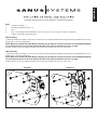
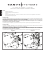
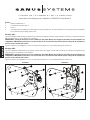
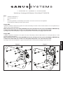
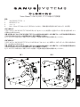
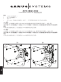
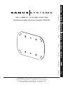
ENGLISH
Spanish
ESPAÑOL
German
DEUTSCH
French
FRANÇAIS
Italian
ITALIANO
Russian
PYCCKO
International Assembly Instructions for models VM100/200
Japanese
中文
Mandarin
Sanus Systems 2221 Hwy 36 West, Saint Paul, MN 55113 7.05.05
Customer Service: (800) 359-5520 • (651) 484-7988 • fax (651) 636-0367
Customer Service Europe: 31 (0)20 5708938 • fax 31 (0)20 5708989
See complementary Sanus products at www.sanus.com
ENGLISH
Assembly Instructions for Vision Mount™ VM100/200 Adapter
Parts:
1
4
4
6
VM100/200 Adapter - a
M5 Flat Head Machine Screws - b
Nuts - c
M4 x 10mm Phillips Pan Head Machine Screws (not shown) - For use with televisions not compatible
with the wall mounts supplied hardware.
VM1 Assembly:
1] Attach the VM100/200 Adapter to the four outer holes on the star shaped Monitor Mount using the M5 Flat Head Machine Screws (b)
and the Nuts (c) as shown in diagram 1.
NOTE: Make sure the M5 Flat Head Machine Screws (b) sit inside the countersunk holes on the VM100/200 Adapter
(a) so the head of the screw is flush with the flat side of the plate and that the nuts are very tight.
2] Attach the television to the adapter and follow the instructions provided with your LCD wall mount.
VMF Assembly:
1] Attach the VM100/200 Adapter (a) to the four outer holes on the VMF Monitor Mount using the M5 Flat Head Machine Screws (b)
and the Nuts (c) as shown in diagram 2.
NOTE: Make sure the M5 Flat Head Machine Screws (b) sit inside the countersunk holes on the VM100/200 Adapter
(a) so the head of the screw is flush with the flat side of the plate and that the nuts are very tight.
2] Attach the television to the adapter and follow the instructions provided with your LCD wall mount.
Diagram 1
Diagram 2
c
b
a
b
a
c
LA
UNIÓN
DE
FORMA
Y
FUNCIÓN
ESPAÑOL
Instrucciones de armado del adaptador Vision Mount™ VM100/200
Piezas:
1
Adaptador VM100/200 - a
4
Tornillos de máquina de cabeza plana M5 - b
4
Tuercas - c
6Tornillos de máquina Phillips M4 x 10 mm (no se muestran) - Para uso en televisores no compatibles con la tornillería
suministrada para montajes en pared.
Armado del VM1:
1] Conectar el adaptador VM100/200 en los cuatro agujeros exteriores del soporte de monitor en forma de estrella utilizando los tornillos
de máquina de cabeza plana M5 (b) y las tuercas (c), como se ilustra en el diagrama 1.
NOTA: Asegurarse de que los tornillos de máquina de cabeza plana M5 (b) se asienten en el interior de los agujeros
contrataladrados del adaptador VM100/200 (a), de manera que la cabeza del tornillo quede a ras con el lado plano
de la placa y las tuercas queden bien apretadas.
2] Conectar el televisor al adaptador y seguir las instrucciones provistas con el soporte de pared para pantalla de cristal líquido.
Armado del VMF:
1] Conectar el adaptador VM100/200 (a) en los cuatro agujeros exteriores del soporte de monitor VMF utilizando los tornillos de
máquina de cabeza plana M5 (b) y las tuercas (c), como se ilustra en el diagrama 2.
NOTA: Asegurarse de que los tornillos de máquina de cabeza plana M5 (b) se asienten en el interior de los agujeros
contrataladrados del adaptador VM100/200 (a), de manera que la cabeza del tornillo quede a ras con el lado plano
de la placa y las tuercas queden bien apretadas.
2] Conectar el televisor al adaptador y seguir las instrucciones provistas con el soporte de pared para pantalla de cristal líquido.
Diagrama 1
Diagrama 2
c
b
a
b
a
c
DIE
EINHEIT
VON
FORM
UND
FUNKTION
Montagehinweise für den Adapter Vision Mount™ VM100/200
Teile:
1
VM100/200 Adapter - a
4
Flachkopfmaschinenschrauben M5 - b
4
Muttern - c
6Phillips Zylinderkopfmaschinenschrauben M4 × 10 mm (nicht dargestellt) - für mit den Wandhalterungen mitgelieferten
Schrauben nicht kompatible Fernseher.
Montage des VMF-Adapters:
1] Den Adapter VM100/200 (a) an den 4 äußeren Bohrungen der Monitorhalterung VMF mit den 4 Flachkopfmaschinenschrauben M5 (b)
und den Muttern (c) wie in Abbildung 2 anbauen.
HINWEIS: Die Flachkopfmaschinenschrauben M5 (b) müssen in den Senkbohrungen des Adapters VM100/200 (a) sitzen,
so dass der Schraubenkopf bündig mit der flachen Seite der Platte abschließt und die Muttern sehr fest angezogen sind.
2] Den Fernseher am Adapter anbauen und die für die LCD-Wandhalterung geltenden Anweisungen einhalten.
Abbildung 1
Abbildung 2
c
b
a
b
a
c
DEUTSCH
Montage des Adapters VM1:
1] Den Adapter VM100/200 an den vier äußeren Bohrungen der sternförmigen Monitorhalterung mit den Flachkopfmaschinenschrauben
(b) und den Muttern (c) wie in Abbildung 1 montieren.
HINWEIS: Die Flachkopfmaschinenschrauben M5 (b) müssen in den Senkbohrungen des Adapters VM100/200 (a) sitzen,
so dass der Schraubenkopf bündig mit der flachen Seite der Platte abschließt und die Muttern sehr fest angezogen sind.
2] Den Fernseher am Adapter anbauen und die Anweisungen für die LCD-Wandhalterung einhalten.
L’ U N I O N
DE
LA
FORME
ET
DE
LA
FONCTION
Instructions d’assemblage pour l’adaptateur VM100/200 Vision Mount™
Pièces :
1
adapteur VM100/200 - a
4
vis à métaux à tête plate M5 - b
4
écrous - c
6vis à métaux à tête cylindrique cruciforme M4 x 10 mm (non illustrées) - Pour une utilisation avec des téléviseurs non compatibles
avec le matériel pour montage mural fourni.
FRANÇAIS
Montage VM1 :
1] Fixez l’adaptateur VM100/200 aux quatres trous extérieurs du support d’écran en forme d’étoile à l’aide des vis à métaux à tête plate
M5 (b) et des écrous (c), tel qu’illustré sur le schéma 1.
REMARQUE : Assurez-vous que les vis à métaux à tête plate M5 (b) sont logées à plat dans les trous fraisés sur
l’adaptateur VM100/200 (a) de façon à ce que la tête de la vis soit au même niveau que le côté plat de la plaque et
que les écrous soient très serrés.
2] Fixez le téléviseur à l’adaptateur et suivez les instructions fournies avec votre montant mural pour écran LCD.
Montage VMF :
1] Fixez l’adaptateur VM100/200 (a) aux quatres trous extérieurs du support d’écran VMF à l’aide des vis à métaux à tête plate M5 (b)
et des écrous (c), tel qu’illustré sur le schéma 2.
REMARQUE : Assurez-vous que les vis à métaux à tête plate M5 (b) sont logées à plat dans les trous fraisés sur
l’adaptateur VM100/200 (a) de façon à ce que la tête de la vis soit au même niveau que le côté plat de la plaque et
que les écrous soient très serrés.
2] Fixez le téléviseur à l’adaptateur et suivez les instructions fournies avec votre montant mural pour écran LCD.
Schéma 1
Schéma 2
c
b
a
b
a
c
L'UNIONE
DI
FORMA
E
FUNZIONE
Istruzioni per il montaggio dell’adattatore Vision Mount™ VM100/200
Parti:
1
Adattatore VM100/200 - a
4
Viti a testa piatta M5 - b
4
Dadi - c
6Viti a testa piatta M4 x 10 mm Phillips (non mostrate) - Da usare con televisori non compatibili
con la minuteria metallica per staffe a parete fornite.
Gruppo VM1:
1] Montare l’adattatore VM100/200 ai quattro fori esterni sulla staffa per monitor a forma di stella usando le viti a testa piatta M5 (b) e
i dadi (c) come mostrato nella figura 1.
NOTA: Assicurarsi che le viti a testa piatta M5 (b) si trovino all’interno dei fori conici sull’adattatore VM100/200 (a)
in modo che la testa della vite sia a filo con il lato piatto della piastra e che i dadi siano ben stretti.
2] Collegare il televisore all’adattatore e seguire le istruzioni fornite con il sistema di montaggio a parete dell’LCD.
Gruppo VMF:
1] Montare l’adattatore VM100/200 (a) ai quattro fori esterni sulla staffa per monitor VMF usando le viti a testa piatta M5 (b) e i dadi
(c) come mostrato nella figura 2.
NOTA: assicurarsi che le viti a testa piatta M5 (b) si trovino all’interno dei fori conici sull’adattatore VM100/200 (a)
in modo che la testa della vite sia a filo con il lato piatto della piastra e che i dadi siano ben stretti.
2] Collegare il televisore all’adattatore e seguire le istruzioni fornite con il sistema di montaggio a parete dell’LCD.
Figura 1
ITALIANO
Figura 2
c
b
a
b
a
c
Инструкция по сборке держателя Vision Mount™ VM100/200
Детали:
Держатель VM100/200 (a) - 1 шт.
Винт крепежный с плоской головкой M5 (b) - 4 шт.
Гайки (c) - 4 шт.
Винт крепежный с крестообразным шлицем M4 x 10 мм (не показан) - 6 шт. - Для использования с телевизорами, несовместимыми
с оборудованием настенного крепления.
Сборка VM1:
1] Прикрепите держатель VM100/200 к крестообразному крепежному устройству с помощью крепежных винтов с плоской
головкой M5 (b) и гаек (c), как показано на рисунке 1.
ПРИМЕЧАНИЕ: Крепежные винты с плоской головкой M5 (b) должны быть утоплены в скрытых
отверстиях на держателе VM100/200 (a) так, чтобы винты полностью вошли с плоской стороны
пластины. Гайки должны быть хорошо затянуты.
2] Установите телевизор на держатель и следуйте инструкциям, включенным в комплект поставки настенного крепления для
жидкокристаллических телевизоров.
Сборка VMF:
1] Прикрепите держатель VM100/200 (a) к крепежному устройству для монитора VMF с помощью крепежных винтов с плоской
головкой M5 (b) и гаек (c), как показано на рисунке 2.
ПРИМЕЧАНИЕ: Крепежные винты с плоской головкой M5 (b) должны быть утоплены в скрытых
отверстиях на держателе VM100/200 (a) так, чтобы винты полностью вошли с плоской стороны
пластины. Гайки должны быть хорошо затянуты.
2] Установите телевизор на держатель и следуйте инструкциям, включенным в комплект поставки настенного крепления для
жидкокристаллических телевизоров.
Рисунок 1
Рисунок 2
PYCCKO
c
b
a
b
a
c
Vision Mount™ VM100/200 アダプタの組み立て説明書
部品:
1
4
4
6
VM100/200 アダプタ - a
M5 皿小ネジ - b
ナット - c
M4 x 10mm プラスのなべ小ネジ (表示されていません) - 同梱の壁掛け用金具で対応できないテレビに使用。
VM1 組み立て:
1] 図 1 のように、VM100/200 アダプタを M5 皿小ネジ (b) とナット (c) を使用して、星型のモニター取り付け金具にある 4 つ
の外側の穴に取り付けます。
注意:M5 皿小ネジ (b) が VM100/200 アダプタ (a) の皿穴の中におさまり、
ネジの頭がプレートの平らな面と同じ高さにな
っていること、
またナットがしっかりと固定されていることを確認してください。
2] テレビをアダプタに取り付け、
ご購入いただいた液晶テレビ壁掛け製品に同梱の説明書に従ってください。
VMF 組み立て:
1] 図 2 のように、VM100/200 アダプタ (a) を M5 皿小ネジ (b) とナット (c) を使用して、VMF のモニター取り付け金具にあ
る 4 つの外側の穴に取り付けます。
注意:M5 皿小ネジ (b) が VM100/200 アダプタ (a) の皿穴の中におさまり、
ネジの頭がプレートの平らな面と同じ高さにな
っていること、
またナットがしっかりと固定されていることを確認してください。
2] テレビをアダプタに取り付け、
ご購入いただいた液晶テレビ壁掛け製品に同梱の説明書に従ってください。
図 1
図2
c
b
a
b
a
c
Vision Mount™ VM100/200 转接器装配说明
零件:
1
4
4
6
VM100/200 转接器 - a
M5 方头机械螺丝 - b
螺母 - c
M4 x 10mm 飞利浦盘头机械螺丝(未显示) - 用于同所提供的墙架五金件不兼容的电视机。
VM1 装配:
1] 使用 M5 方头机械螺丝 (b) 螺母 (c) 将 VM100/200 转接器安装在星状显示器架的四个外侧孔上,如图 1 所示。
注意:确保 M5 方头机械螺丝 (b) 安装在 VM100/200 转换器 (a) 的埋头孔内,以便使螺丝头部与板平面齐平并能使螺母
旋紧。
2] 将电视机安装到转换器上,然后按照您的 LCD 墙架附带的说明进行操作。
VMF 装配:
1] 使用 M5 方头机械螺丝 (b) 螺母 (c) 将 VM100/200 转接器安装在 VMF 显示器架的四个外侧孔上,如图 2 所示。
注意:确保 M5 方头机械螺丝 (b) 安装在 VM100/200 转换器 (a) 的埋头孔内,以便使螺丝头部与板平面齐平并能使螺母
旋紧。
2] 将电视机安装到转换器上,然后按照您的 LCD 墙架附带的说明进行操作。
图 1
图2
中文
c
b
a
b
a
c