1
Operating Instructions
Ceiling Mount Bracket
WV-Q175
WV-Q175E
Model No.
Before attempting to connect or operate this product,
please read these instructions carefully and save this manual for future use.
The model number is abbreviated in some descriptions in this manual.
CONTENTS
Preface ..........................................................................................................................................3
Precautions ...................................................................................................................................3
Major operating controls and their functions .................................................................................5
Installations ...................................................................................................................................5
Specifications ..............................................................................................................................10
Standard accessories ..................................................................................................................11
2
Preface
This ceiling embedded bracket is exclusively designed to mount a color CCTV camera or a network camera. Refer to the catalog or the operating instructions of the camera for supported
cameras.
This bracket is an embedded type to reduce the exposed portion of the camera body.
Precautions
• Refer installation work to the dealer.
Installation work requires technique and experiences. Failure to observe this may cause
fire, electric shock, injury, or damage to the product.
• Be sure to consult the dealer.
• Use only the specified camera.
Failure to observe this may cause a fall of an inappropriate camera resulting in injury or
accidents.
• Refer to the catalog or the operating instructions of the camera for supported cameras.
• Select an installation area.
If a selected area is too weak to support the total weight, a fall of the product may occur
resulting in injury.
• Installation work shall be started after sufficient reinforcement.
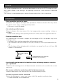
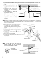
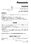
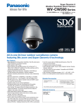
• The installation area shall have 210 mm {8-1/4 inches} or more space behind the ceiling.
• The thickness of the ceiling board for installation can range from 9 mm to 40 mm {3/8
inches to 1-9/16 inches}.
210 mm {8-1/4 inches}
or more
Ceiling board: from 9 mm to 40 mm
{3/8 inches to 1-9/16 inches}
• Avoid installing this bracket in the locations where salt damage occurs or corrosive
gas is produced.
Otherwise, the mounting portions will deteriorate and accidents such as a fall of the camera
may occur.
• The screws and fixation mechanisms shall be tightened securely.
Failure to observe this may cause a fall of the camera resulting in injury.
• Periodic inspections shall be conducted.
Rust on the metal parts or screws may cause a fall of the product resulting in injury.
• Consult the dealer for the inspections.
3
• Do not rub the edges of metal parts with your hand.
Failure to observe this may cause injury.
• Make sure that the installation area is strong enough to hold the total weight of the camera
assembly before installation.
• The camera and the ceiling mount bracket should be fixed using the provided fixing
screws, and make sure that the both of them are fixed firmly.
• When the ceiling mount bracket is not necessary anymore, remove from the ceiling.
• Avoid installing in the following locations.
• Locations where it may get wet from rain or water splash (not only outdoor)
• Locations where a chemical agent is used such as a swimming pool
• Locations subject to steam and oil smoke such as a kitchen
• Locations where radiation or x-ray emissions are produced
• Locations where it may be damaged by briny air such as seashores
• Locations where the temperature is not within the ambient temperature of the camera in
use and this product
• Locations subject to vibrations (This product is not designed for on-vehicle use.)
• Locations where the temperature may rapidly change such as the peripheral areas of
the air outlets of air conditioners or doors facing outside. (In case of installing the camera in such locations, the dome cover may become foggy or condensation may be
caused on the cover.)
• The screws and bolts must be tightened with an appropriate tightening torque according to
the material and strength of the installation area. After tightening the screws or bolts, perform visual check to ensure tightening is enough and there is no backlash.
4
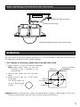
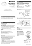
Major operating controls and their functions
Roof space
Safety wire angle (Accessory)
Safety wire (Accessory)
* Read the operating instructions of the camera as well.
Installations
Be sure to read "Precautions" before installation. It is recommended to read them while referring
the operating instructions of the camera together.
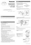
1. Put Template A (accessory) against the ceiling and make a hole.
q Make 4 holes of 12 mm {1/2 inches} in diameter.
Note: Make these holes so that the
Ceiling face
Panasonic logo is directed to the
desired side.
w Remove the center part from the template.
Brand logo side
e Make a hole of 180 mm {7-1/16 inches}
ø180 mm
in diameter.
{7-1/16 inches}
The ceiling holes are
shown in the drawing
Template A
at right.
→
ø12 mm {1/2 inches}
(4 positions)
Important: Make a hole precisely. When the opened hole is bigger or deformed too much, the
ceiling mount bracket cannot be stuck on the ceiling board securely.
5
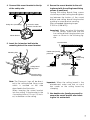
2. Install two anchor bolts (locally procured: M10 recommended) into the concrete ceiling.
q Install an anchor bolt in the
center of the hole made in the
2nd Anchor bolt
1st Anchor bolt (locally procured)
step 1.
(locally procured)
Nut (locally procured)
w Determine the anchor bolt
Determine the anchor
Anchor
bolt
length by use of Template B
bolt length
(accessory).
e Use Template B to decide the
nut position, and fix it.
134 mm
Template B
{5-1/4 inches}
(Mount the nut so that the distance between the bottom surfaces of the nut and ceiling is
Ceiling board
adjusted to 134 mm {5-1/4
Install the anchor bolt in the center
of the hole
inches}.)
Note: If there is already an anchor bolt installed, the anchor bolt can be used as a 2nd anchor
bolt. Make sure that the distance between the 1st and 2nd anchor bolts is 1 000 mm {3.28
feet} or less before use.
3. Mount the safety wire angle (accessoAnchor bolt
ry) on the 2nd anchor bolt and connect the safety wire (accessory) to the
angle.
w Insert
q Disconnect the safety wire from the safe- q Disconnect
ty wire angle.
w Engage the face marked q with the
anchor bolt.
e Bend the face marked w.
r Connect the safety wire to the safety wire Safety wire
angle again.
Mark q
Upper side
Mark w
e Bend
Lower
side
Safety wire angle
r Connect
Note: To use the anchor bolt that was
already installed, the use of 2 spacer
nuts (locally procured) is helpful.
Spacer nuts
Spacer nuts
(locally procured)
Safety wire angle
Safety wire
Existing anchor bolt
6
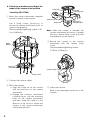
4. Connect this mount bracket to the tip
of the safety wire.
Roof space
Safety wire (Accessory)
Insert the mount
bracket into the hole
6. Secure the mount bracket to the ceiling board with the ceiling board fixing
screws (4 positions).
Turning the ceiling board fixing screws
clockwise provides ceiling board tightening between the bottom of the mount
bracket and ceiling board fixing bracket
resulting in mount bracket securing.
(Recommended tightening torque:
0.78 N·m {0.58 lbf·ft})
Important: When securing this bracket
on the ceiling, make sure that the
four ceiling board fixing brackets are
open as shown in the following figure.
Mount bracket
1st anchor bolt
5. Insert the 1st anchor bolt into the
mounting hole of the mount bracket.
Double nuts (locally
procured)
Mounting hole
Ceiling
board fixing
screw
Ceiling board
fixing bracket
Ceiling board
fixing screw
Direction of the
Panasonic logo
Note: The Panasonic logo will be directed to the ceiling board fixing screw
which is secured on the side
described in the illustration.
When inserting the mount bracket
into the ceiling, fit the bracket in the
4 mounting holes of 12 mm {1/2 inches} in diameter on the ceiling.
Ceiling board
Turn clockwise
Important: When the ceiling board is the
plasterboard, make sure that no crack
was made on the ceiling board by
clamping.
7. Use double nuts (locally procured) to
secure the mount bracket after inserting the 1st anchor bolt.
7
8. Follow the procedure according to the
model of the camera to be installed.
Protrusion
<Installing WV-CF504>
q Mount the camera attachment (supplied
with the camera) to this bracket.
Use 4 fixing screws (accessory) to
secure the camera attachment firmly as
shown in the drawing.
(Recommended tightening torque: 0.78
N·m {0.58 lbf·ft})
Camera
mounting hole
Fixing screw hole
Single rib
Attachment
mounting hook
Note: When the camera is secured, the
camera attachment protrusion is aligned
with the camera fixing screw hole and
the double rib on the camera.
r Secure the camera to the camera
attachment with the camera fixing
screw.
(Recommended tightening torque:
0.78 N·m {0.58 lbf·ft}).
Mount
bracket
Camera
attachment
Camera fixing screw
Fixing screws
w Connect the camera cables.
e Mount the camera.
a. Align the single rib on the camera
with the protrusion on the camera
attachment.
b. Engage the camera's attachment
mounting hooks with the mounting
holes on the camera attachment,
and then rotate the camera in the
direction of the arrow to secure the
camera to the camera attachment
without any backlash.
8
t Adjust the camera.
Refer to the operating instructions of the
camera.
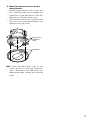
9. Mount the decorative cover on this
mount bracket.
• Mount the decorative cover on the camera mounting plate with engaging the
projections of the decorative cover with
the hooks for the decorative cover.
• Turn the decorative cover clockwise until
the cover clicks while pressing the cover
upward to lock the cover.
Hooks for the
decorative
cover
Projection
Note: Mount the decorative cover on the
mount bracket so that the Panasonic
logo is directed to the side which was
determined when making the mounting
holes.
9
Specifications
Ambient temperature
Dimensions
Mass
Finish
10
–10 °C to +50 °C {–14 °F to 122 °F}
204.4 mm {8-1/16 inches} in diameter x 143.4 mm {5-5/8 inches}
in height
Approx. 700 g {1.55 lbs}
Main body: Metal
Decorative cover: ABS plastic
Standard accessories
Operating Instructions (this book) ................. 1 pc.
The following are for installation.
Safety wire ..................................................... 1 pc.
Safety wire angle ........................................... 1 pc.
Template A .................................................... 1 pc.
Template B .................................................... 1 pc.
Fixing screw (M4 x 8) .................................... 5 pcs. (incl. 1 spare screw)
11
For U.S. and Canada:
Panasonic System Networks Company
of America,
Unit of Panasonic Corporation
of North America
www.panasonic.com/business/
For customer support, call 1.800.528.6747
Three Panasonic Way, Secaucus,
New Jersey 07094 U.S.A.
For Europe and other countries:
http://panasonic.net
Importer's name and address to follow EU rules:
Panasonic Testing Centre
Panasonic Marketing Europe GmbH
Winsbergring 15, 22525 Hamburg F.R.Germany
Panasonic Canada Inc.
5770 Ambler Drive, Mississauga,
Ontario, L4W 2T3 Canada
(905)624-5010
www.panasonic.ca
© Panasonic System Networks Co., Ltd. 2011
Ns0211-1061
3TR006878BZA
Printed in China