1
Ceiling Mount Bracket
Operating Instructions
WV-Q155C
WV-Q155CE
WV-Q155S
WV-Q155SE
Model No.
Before attempting to connect or operate this product,
please read these instructions carefully and save this manual for future use.
The model number is abbreviated in some descriptions in this manual.
CONTENTS
Preface ....................................................................................................................................... 2
Precautions ................................................................................................................................ 2
Major Operating Controls and Their Functions .......................................................................... 4
Installations ................................................................................................................................ 5
Specifications ................................................................................................................ back cover
Standard Accessories ................................................................................................... back cover
Preface
This ceiling mount bracket is exclusively designed to mount the network camera on a ceiling.
Refer to the catalog or the installation guide of the camera for supported cameras.
This bracket can be used for an area with weak pull-out strength such as plasterboard in a
double ceiling.
This bracket is an embedded type to reduce the exposed portion of the camera body.
• WV-Q155C: Clear dome cover
• WV-Q155S: Smoked dome cover (approx. 50 % of transmittance)
Precautions
• Refer installation work to the dealer.
Installation work requires technique and experiences. Failure to observe this may cause
fire, electric shock, injury, or damage to the product. Be sure to consult the dealer.
• Avoid installing this bracket in the locations where salt damage occurs or corrosive
gas is produced.
Otherwise, the mounting portions will deteriorate and accidents such as a fall of the camera
may occur.
• Use only the specified camera.
Failure to observe this may cause a fall of an inappropriate camera resulting in injury or
accidents. Refer to the catalog or the installation guide of the camera for supported cameras.
• The screws and fixation mechanisms shall be tightened securely.
Failure to observe this may cause a fall of the camera resulting in injury.
• The measures of protection against a fall of the camera shall be taken.
Failure to observe this may cause injury. Be sure to install the safety wire.
2
• Select an installation area that can support the total weight.
If a selected area is too weak to support the total weight, a fall of the product may occur
resulting in injury. Installation work shall be started after sufficient reinforcement.
• Periodic inspections shall be conducted.
Rust on the metal parts or screws may cause a fall of the product resulting in injury. Consult
the dealer for the inspections.
• Do not rub the edges of metal parts with your hand.
Failure to observe this may cause injury.
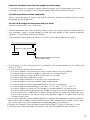
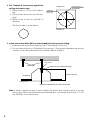
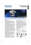
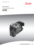
• Consult the dealer about the installation area to select a strong ceiling area. Make sure that
the installation area is strong enough to hold the total weight of the camera assembly
(approx. 1.7 kg {3.6 lbs.}) before installation.
• The installation area shall have 180 mm {7-1/8"} or more space behind the ceiling.
180 mm {7-1/8"} or more
Ceiling board: between 9 mm {3/8"}
and 40 mm {1-9/16"}
• The thickness of the ceiling board for installation can range between 9 mm {3/8"} and
40 mm {1-9/16"}.
• Avoid installing in the following locations.
• Locations where it may get wet from rain or water splash (not only outdoor)
• Locations where a chemical agent is used such as a swimming pool
• Locations subject to steam and oil smoke such as a kitchen
• Locations near flammable gas or vapor
• Locations where radiation or x-ray emissions are produced
• Locations subject to strong magnetic field or radio waves
• Locations where it may be damaged by briny air such as seashores
• Locations where the temperature is not within –10 °C - +50 °C {14 °F - 122 °F}.
• Locations subject to vibrations (This product is not designed for on-vehicle use.)
• Locations where the temperature may rapidly change such as the peripheral areas of
the air outlets of air conditioners or doors facing outside. (In case of installing the camera in such locations, the dome cover may become foggy or condensation may be
caused on the cover.)
• The screws and bolts must be tightened with an appropriate tightening torque according to
the material and strength of the installation area. After tightening the screws or bolts, perform visual check to ensure tightening is enough and there is no backlash.
• The pull-out strength of the installation area shall be 196 N {20 kgf} or more per 1 screw.
• The protection sheet attached to the dome cover shall be peeled off after installation.
3
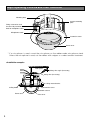
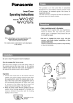
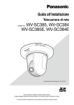
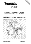
Major Operating Controls and Their Functions
Mounting base
Camera mounting
plate
Fixing screw to be used
for cover fall prevention
Hole for microphone cable
Microphone stand*
Decorative cover
Dome cover
* If a microphone is used, mount the microphone on the rubber-made microphone stand.
Unless the microphone is used, cut the rubber with a nipper or conduct another treatment.
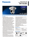
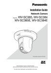
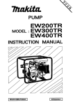
<Installation sample>
Roof space
Safety wire angle (Accessory)
Safety wire (Accessory)
Ceiling mount bracket
Ceiling board
Decorative cover
Network camera
Dome cover
4
Inner cover
Installations
Be sure to read "Precautions" before installation. The Installation Guide of the network camera
shall be read as well.
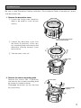
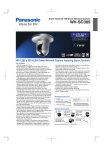
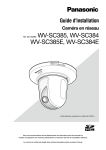
1. Remove the decorative cover.
q Loosen the fixing screw (unremovable) to be used for cover fall prevention.
Fixing screw to be used for
cover fall prevention
w Unhook the decorative cover from
the hooks (3 positions) of the camera mounting plate and remove the
decorative cover by turning it counterclockwise.
e Take the inner cover out.
Hook
LO
CK
FRONT
FRON
T
Screw (M4)
(a)
LO
CK
Camera mounting plate
FRON
T
FRONT
2. Remove the camera mounting plate.
Remove the screws (M4, 3 positions)
and remove the camera mounting plate
by turning it counterclockwise.
Disengage the portion (a) from the hole
(b) (2 positions).
(b)
5
3. Put Template A (accessory) against the
ceiling and make a hole.
q Make 4 holes of 12 mm {1/2"} in diameter.
w Remove the center part from the template.
e Make a hole of 160 mm {6-5/16"} in
diameter.
ø12 mm {1/2"}
(4 positions)
Ceiling face
ø160 mm
{6-5/16"}
* The hole shape is shown below.
Template A
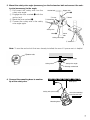
4. Install two anchor bolts (M10 recommended) into the concrete ceiling.
q Determine the anchor bolt length by use of Template B (accessory).
w Position the nut by use of Template B (accessory). (The distance between the bottom
surfaces of the ceiling board and nut shall be 136 mm {5-3/8"}.)
Use a nut
Anchor bolt
Template B
Determine the anchor bolt length
136 mm {5-3/8"}
Ceiling board
Install the anchor bolt in the center of the hole
Note: If there is already an anchor bolt installed, the anchor bolt can be used as a second
anchor bolt. Make sure that the distance between the 1st and 2nd anchor bolts is 1 000
mm {39-3/8"} or less before use.
6
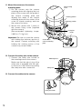
5. Mount the safety wire angle (accessory) on the 2nd anchor bolt and connect the safety wire (accessory) to the angle.
Upper side
q Disconnect the safety wire from the
Anchor bolt
Mark w
safety wire angle.
w Engage the face marked q with the
w Insert
e Bend
anchor bolt.
q Disconnect
e Bend the face marked w.
r Connect the safety wire to the safety
wire angle again.
Safety wire
Mark q
Lower
side
Safety wire angle
r Connect
Note: To use the anchor bolt that was already installed, the use of 2 spacer nuts is helpful.
Spacer nuts
Spacer nuts
Safety wire
Safety wire angle
Existing anchor bolt
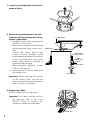
6. Connect the mounting base to another
tip of the safety wire.
Roof space
Safety wire (Accessory)
Insert the mounting
base into the hole
Mounting base
7
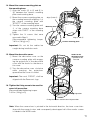
7. Insert the mounting base into the hole
made in Step 3.
8. Secure the mounting base to the ceiling board with the ceiling board fixing
screws (4 positions).
q Engage the top of the mounting base
with the 1st anchor bolt.
w Secure the mounting base by turning
the ceiling board fixing screws clockwise.
Turning the ceiling board fixing
screws clockwise provides ceiling
board tightening between the bottom
of the mounting base and ceiling
board fixing bracket resulting in
mounting base securing.
(Recommended tigtening torque:
0.78 N·m {8.0 kgf·cm}
e Secure the top of the mounting base
with double nuts.
1st anchor bolt
Nut
Insert the anchor bolt
Double nuts
Ceiling board
fixing screw
Ceiling
board fixing
bracket
Ceiling board
Turn clockwise
Important: When securing this bracket
on the ceiling, make sure that the
four ceiling board fixing brackets are
open as shown in the figure.
9. Prepare the cables.
Run the cables from the cable inlet.
Important: The cables shall be run from
the opposite side of the mark,
FRONT. Failure to observe this
makes the cables unconnectable.
FRONT
Cable inlet
8
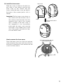
10. Install the inner cover.
Slide the covers located on the both lateral sides of the camera and put the
inner cover on the camera until the
hooks inside the inner cover are held in
the holes of the camera (until a click is
heard).
Important: Put the inner cover down on
the camera until the outside cover of
the camera cannot be seen from the
opening (from which the camera
lens is visible) of the inner cover. If
this integration is not successfully
performed, the inner cover may be
removed or the hidden part at the
top of the screen may become larger in the WIDE mode.
How to remove the inner cover
Press the inner cover from the front and rear
sides inward (at the same vertical position as
the hooks) to bend the cover and remove the
cover from the camera.
Inner cover
Cover
Hook
Put on until a click is
heard
Press from the front and rear
sides inward to bend
9
11. Mount the camera on the camera
mounting plate.
q Put the camera onto the camera
mounting plate with aligning the lock
plate of the camera with the guide of
the camera mounting plate and
aligning the center of the camera
mounting plate with the center of the
screw for tripod mounting, and turn
the camera clockwise.
w Secure the camera with 1 piece of
the camera fixing screw (supplied
with the camera).
(Recommended tightening torque:
0.68 N·m {7.0 kgf·cm})
Camera fixing
screw
Rotating portion
Stationary portion
Lock plate
FRON
Guide
T
LO
CK
Important: Be sure to mount the camera
with holding the stationary portion of
the camera. Camera mounting with
holding the rotating portion of the
camera may cause trouble.
12. Connect the safety wire to the camera.
q Connect the safety wire locked on
the mounting base to the camera.
Make sure that the apical ring of the
safety wire is engaged with the safety wire hook of the camera by pulling
the safety wire after connection.
Center of the
camera mounting
plate
Mounting base
FRONT
Safety wire
FRON
T
LO
C
K
13. Connect the cables to the camera.
Safety wire hook
10
CK
LO
Align A with A
FRON
T
FRONT
END
Mounting base
Align B with B
START
14. Mount the camera mounting plate on
the mounting base.
q Align the marks (A to A and B to
B) between the camera mounting
plate and mounting base.
w Mount the camera mounting plate on
the mounting base with aligning g of
the camera mounting plate with
"STARTh" of the mounting base.
e Turn the camera mounting plate until
g of the camera mounting base
aligns with "ENDh" of the mounting
base.
r Tighten the 3 screws that were
removed in Step 2.
(Recommended tightening torque:
1.6 N·m {16 kgf·cm})
Camera mounting plate
Important: Do not let the cables be
caught during installation work.
FRON
Hooks for the
decorative cover
*1 position on the
rear side
T
LO
CK
15. Mount the decorative cover.
q Mount the decorative cover on the
camera mounting plate with engaging the projections of the decorative
cover with the hooks for the decorative cover.
w Turn the decorative cover clockwise
while pressing the projections
upward and the cover is locked.
FRONT
Important: The mark, "FRONT", shall be
aligned with the Panasonic logo.
16. Tighten the fixing screw to be used for
cover fall prevention.
(Recommended tightening torque:
1.6 N·m {16 kgf·cm})
Projections
Fixing screw to be used for cover fall prevention
Note: When the camera lens is pointed in the horizontal direction, the inner cover interferes with the camera’s view, and consequently about upper half of the monitor screen
is hidden in the WIDE mode.
11
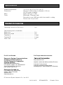
Specifications
Ambient temperature:
Dimensions:
Mass:
Finish:
–10 °C to + 50 °C {14 °F to 122 °F}
185 mm {7-5/16 inches} in diameter x 145 mm
{6-7/16 inches} in height
Approx. 800 g {1.77 lbs}
Main body: Treatment steel
Decorative cover: ABS resin with silver metallic coating
Dome cover: Acrylic resin
Standard Accessories
Operating Instructions (this book) ............................. 1 pc.
The following are for installation
Safety wire ................................................................. 1 pc.
Safety wire angle ....................................................... 1 pc.
Template A ................................................................ 1 sheet
Template B ................................................................ 1 sheet
Inner cover ................................................................ 1 pc.
For U.S. and Canada:
Panasonic System Communications
Company of North America,
Unit of Panasonic Corporation
of North America
www.panasonic.com/business/
For customer support, call 1.800.528.6747
Three Panasonic Way, Secaucus,
New Jersey 07094 U.S.A.
For Europe and other countries:
http://panasonic.net
Importer's name and address to follow EU rules:
Panasonic Testing Centre
Panasonic Marketing Europe GmbH
Winsbergring 15, 22525 Hamburg F.R.Germany
Panasonic Canada Inc.
5770 Ambler Drive, Mississauga,
Ontario, L4W 2T3 Canada
(905)624-5010
www.panasonic.ca
© Panasonic System Networks Co., Ltd. 2012
Ns1010-3012
3TR006652DZA
Printed in China