1
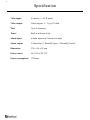
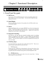
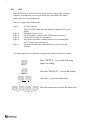
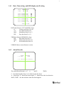
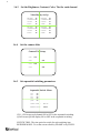
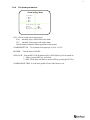
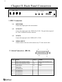
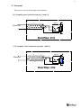
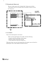
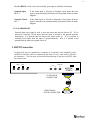
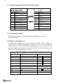
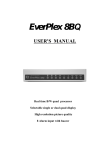
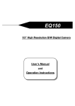
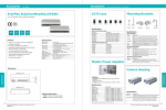
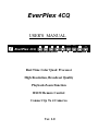
EverPlex 4CQ USER'S MANUAL Freeze Seq EverPlex 4CQ + NEXT P. Real Time Color Quad Processor High Resolution, Broadcast Quality Playback Zoom Function RS232 Remote Control Connect Up To 4 Cameras Ver. 1.0 Set DEFAULT Table of Content Notice.........................................................................................................................1 Important Messages ..................................................................................................2 Introduction...............................................................................................................3 Specification ..............................................................................................................4 Chapter I Functional Description....................................................................5 1. Front Panel Keypads..........................................................................................5 1.1 Full Screen ....................................................................................................5 1.2 Quad Display ................................................................................................5 1.3 Freeze ........................................................................................................5 1.4 Sequential Switching.....................................................................................5 1.5 VCR Play Back .............................................................................................5 1.6 Set ........................................................................................................6 1.6.1 Date, Time Setting, and OSD display on/off setting...............................7 1.6.2 Alarm Records ........................................................................................7 1.6.3 Set the Brightness, Contrast, Color, Tint for each channel .....................8 1.6.4 Set the camera titles ................................................................................8 1.6.5 Set sequential switching parameters .......................................................8 1.6.6 Set alarm parameters...............................................................................9 Chapter II Back Panel Connection ...............................................................10 1. BNC Connectors..............................................................................................10 1.1 Monitor .......................................................................................................10 1.2 VCR out ......................................................................................................10 1.3 VCR In ....................................................................................................10 1.4 Video input ..................................................................................................10 2. Alarm Connectors (DB-15) .............................................................................10 2.1 Alarm out .................................................................................................... 11 2.1.1 Normally open connection.................................................................... 11 2.1.2 Normally closed connection ................................................................. 11 2.2 Alarm in and alrm reset...............................................................................12 2.2.1 Alarm in ................................................................................................12 2.2.2 Alarm reset............................................................................................13 3. RS232 Connector .............................................................................................13 3.1 The pin assignment of the 9 pin D-SUB connector.....................................14 3.2 Transmission setting....................................................................................14 3.3 Remote control protocol..............................................................................14 3.4 Alarm message sent via RS232...................................................................15 1 Notice This manual is presented to the users of EverPlex 4CQ by EverFocus Electronics Corp. With years of engineering researches, EverFocus has spared no effort to provide the high quality products to the worldwide users. For the policy of continual product improvement, EverFocus reserves the right to make changes to the product specifications and documentation without notice. All the components of the products, including accessories, components, and outlook, are based on the agreements if each deals to satisfy all kinds of users. Meanwhile, please be advised that every step of operation must follow the instruction of this manual to keep EverPlex 4CQ working under the best condition. Please notice that EverFocus will not be charged any claims or renewing cases resulted from inappropriate operation. 2 Important Messages: 1. To prevent fire or shock hazard, do not expose this equipment to the environment of high humidity and dust. So, do not use it in an unprotected outdoor installation or any area classified as a wet area. 2. Installation environment: The temperature should be kept between -10oC ~ +50oC, humidity under 90%. For safety sake, do not disseminate the unit or put it on an unstable base. 3. Ventilation: Openings in the enclosure are provided for ventilation and to ensure reliable operation of the unit and to protect it from overheating. These openings must not be blocked or covered. This unit should not be placed in a built-in installation unless proper ventilation is provided. 4. Cleanse: Unplug the unit from the outlet before cleansing. Do not use liquid cleaners or aerosol cleaners. Use a damp cloth to clean it. 5. Overload: Do not overload outlets and extension cords as this may result in a fire or electric shock. 6. Power-cord Protection: Power-supply cords should be routed so that they are not likely to be walked on or pinched by items placed upon or against them, paying particular attention to cords at plugs, convenience receptacles, and the point where they exit from the appliance. 7. Object and Liquid Entry: Never push objects of any kind into this unit through openings as they may touch dangerous voltage points or short-out parts that could result in a fire or electric shock. Never spill liquid of any kind on the unit. 8. Service: Do not attempt to service this unit yourself as opening or removing covers may expose you to dangerous voltage of other hazards. Refer all servicing to qualified service personnel. 3 Introduction EverPlex 4CQ, a real time color Quad and 4 channel auto switcher, is the best choice for multiple monitoring and recording. The superior video quality is achieved by adopting the advance multi-media technology. The picture of Quad display is sharp and clear because Everplex 4CQ is featured with CCIR601 full resolution and 16 million colors. Main Features: Real-time Quad display. High Resolution 720 x 576 (PAL), 720 x 480 (NTSC). 16 million colors. Up to 4 camera inputs and quad display. Video loss detection. Different border colors indicate page selection. Independent brightness, contrast, color and tint adjustments for every channel. Built-in timer and and title generator. Alarm input with built-in buzzer. Programmable Quad and 4 channel auto switcher outputs. Playback Zoom and Freeze function. RS232 Remote Control. User-friendly front panel design. 4 Specification Video input: 4 cameras + 1 VCR inputs Video output: Video output x 2, 1V p-p/75 ohm Title: Up to 6 characters Timer: Built-in real time clock Alarm input: 4 alarm inputs and 1 alarm reset input Alarm output: 2 Alarm Out (1 Normally Open, 1 Normally Closed) Dimension: 239 x 166 x 55 mm Power source: AC 24V or DC 12V Power consumption: 17W max. 5 Chapter I Functional Description Freeze Seq EverPlex 4CQ + NEXT P. Set DEFAULT 1. Front Panel Keypads 1.1 Full Screen Press any key of FULL SCREEN, the picture of the corresponding quadrant will fill the whole screen of the monitor display. Press the same key again, the quad display will come out. 1.2 Quad Display Press the Quad Display, the picture of the quadrant video will fill the whole screen of the monitor display. 1.3 Freeze During quad display mode, you can press FREEZE key to freeze the video on the monitor. Press this key again to de-freeze the video. If you press any Full Screen Key, there will be merely that video input de-frozen. Judging by the channel title blinking, users can be aware of freezing status. 1.4 Sequential Switching Press SEQ key will enter the auto sequential switching mode, the switching sequence is programmed in SET function. It can be displayed live quad and full screen sequentially on the main monitor according to the programmed switching sequence. Press the SEQ key again to exit the auto sequential mode and stay the last screen display. 1.5 VCR Play Back Press PLAY BACK key to play back the recorded video from VCR. special functions implemented in the play back mode. A. There are two ZOOM function Pressing any FULL SCREEN key during playback will zoom in the picture of the corresponding quadrant to the whole screen of the monitor display. Press the same key again to stop the zoom function and go back to the normal playback video. B FREEZE function Press the FREEZE key during zoom mode to freeze the current frame. this key again to de-freeze the video. Pressing 6 1.6 Set Press the SET key to set time/date, title on/off, picture, camera titles, switching sequence, switching time period, alarm sensor type, alarm hold time, and the alarm/video loss records displaying. There are 6 pages in the setting mode : Page 1 : Page Page Page Page Set Time and Date. Turn ON/OFF the time, date, title display for Quad or Full screen display. Display the alarm records. Set the brightness, contrast, color, and tint for each camera. Change the title name of each camera. Program the sequential switching sequence and switching hold time. Set the screen refresh mode. Set the alarm sensor type, alarm hold time, buzzer on/off and Security. 2: 3: 4: 5: Page 6: The following keys are re-defined in setting mode (Definition under the keypad). NEXT P. DEFAULT Press “NEXT P.” to go to the following pages for setting. Press the “DEFAULT” to reset the setting. Press the +/- keys to set the value. + Press the cursor key to select the item to set. 7 1.6.1 Date, Time setting, and OSD display on/off setting DATE: TIME: 2000-01-01 01:01:01 QUAD SCREEN DATE: QUAD SCREEN TIME: QUAD SCREEN TITLE: ON ON ON FULL SCREEN DATE: FULL SCREEN TIME: FULL SCREEN TITLE: ON ON ON VERSION N.NN DATE data format is CCYY-MM-DD, where CC : Century code from 19 to 20 YY : Year data from 00 to 99 MM : Month data from 01 to 12 DD : Day data from 01 to 31 TIME data format is HH-MM-SS, where HH : Hour data from 00 to 23 MM : Minute data from 00 to 59 SS : Second data from 00 to 59 VERSION shows current firmware version 1.6.2 Alarm Records ALARM C A DATE RECORDS TIME 3 S 1997-03-24 10:00:00 The Alarm Record format is : (C A DATE TIME) C : the channel number from 1 to 4 which invokes the alarm A : Alarm type, 'S' - alarm from sensor input, 'V' - alarm from video loss detection DATE, TIME : the date and time when the alarm happens 8 1.6.3 Set the Brightness, Contrast, Color, Tint for each channel Video Display Set Up 1.6.4 BRIGHT: 32 CONTRAST:27 COLOR: 31 TINT: 32 BRIGHT: 32 CONTRAST:27 COLOR: 31 TINT: 32 BRIGHT: 32 CONTRAST:27 COLOR: 31 TINT: 32 BRIGHT: 32 CONTRAST:27 COLOR: 31 TINT: 32 Set the camera titles Camera Title Setup CH1: CH1 CH2: CH3: CH2 CH3 CH4: 1.6.5 CH4 Set sequential switching parameters Sequential Switch Menu CH1: CH2: CH3: CH4: QUAD: ON ON ON ON ON SWITCH TIME : REFRESH MODE : 03 SEC FIELD CH1 - CH4 to turn each channel ON or OFF in the sequential switching QUAD to turn QUAD display ON or OFF in the sequential switching SWITCH TIME : The time period to switch for each switching item REFRESH MODE : To set the screen refresh by 'FRAME' or by 'FIELD'. 9 1.6.6 Set alarm parameters Alarm Setting Menu CH 1 2 3 4 SENSOR N.O. N.O. N.O. N.O. ALARM RESET IN : BUZZER : KEY LOCK : ALARM HOLD TIME: N.O. ON OFF 05 SEC CH1 - CH4 to set the sensor input type as 'N.O.' : normally open, closed will invoke alarm 'N.C.' : normally closed, open will invoke alarm 'closed' means to short the alarm signal line to the ground ALARM RESET IN : To set alarm reset input type as 'N.O.' or 'N.C.' BUZZER : Turn the buzzer ON/OFF KEY LOCK : Turn the KEY LOCK function ON or OFF when key lock is turned on 1. All keys except SET key are locked 2. KEY LOCK stays ON until we turn it OFF by pressing the SET key ALARM HOLD TIME : It is the time period of buzz if the buzzer is on. 10 Chapter II Back Panel Connection AC24V VIDEO INPUT MONITOR VCR IN OUT OUT ALARM I/O DC12V 1. BNC Connectors 1.1 MONITOR Connect this output port to the main monitor. 1.2 VCR OUT Connect this output port to the VIDEO IN of VCR. The quad video output of live video is obtained from this connector. 1.3 VCR IN Connect this input port to the VIDEO OUT of VCR. 1.4 VIDEO INPUT Connect camera video out to this connector by a 75 ohm coaxial cable. 8 1 2. Alarm Connectors (DB-15) 15 PIN # 1 2 3 4 5 6 7 8 NAME Alarm Out Common contact Alarm Out Normally Closed Alarm Reset GROUND ALARM IN 4 ALARM IN 3 ALARM IN 2 ALARM IN 1 PIN # 9 10 11 9 NAME Alarm Out Normally Open TXD * RXD * 11 2.1 Alarm out There are two ways to do the alarm out connection: 2.1.1 Normally Open Connection (use pin # 1 and # 9) 2 8 1 RELAY 15 COIL Alarm out 9 EverPlex 4CQ 2.1.2 Normally Closed Connection (use pin # 1 and # 2) 2 8 1 RELAY 15 9 EverPlex 4CQ COIL Alarm out 12 2.2 Alarm in and Alarm reset There are 4 alarm sensors in for 4 channels and 1 alarm reset in, all these 5 alarm inputs can be set to Normally Open or Normally Closed by user and the setting menu. ALARM CIRCUIT SENSOR 1 SENSOR 2 SENSOR 3 SENSOR 4 2 8 9 15 ALARM RESET 1 EverPlex 4CQ 2.2.1 ALARM IN There are four alarm inputs for each camera. When any alarm signal happens, the machine will do the following: 1. Switch to the full screen display of this channel. 2. Blink the channel ID with alarm message. 3. Turn on the buzzer if the buzzer setting is on. When many alarms come up in the alarming status, the monitor screen will switch to quad display to show all the channels which have alarm in. 13 The ALARM IN can be selected as normally open input or normally closed input: Normally Open : (N.O.) Normally Closed : (N.C.) If the alarm input is selected as Normally Open input, then the input is opened normally and shorted to the ground means an alarm happens. If the alarm input is selected as Normally Closed input, then the input is shorted to the ground normally and opened means an alarm happens. 2.2.2 ALARM RESET External alarm reset signal is used to reset the alarm and turn the buzzer off. If it is selected as Normally Closed input, then the input is shorted to the ground normally. Furthermore, it is opened when an alarm reset signal comes in. If it is selected as Normally Open input, then the input is opened normally. Also it is shorted to the ground when an alarm reset signal comes in. 3. RS232 Connection EverPlex 4CQ may be controlled by a computer or a terminal via the standard 9 pin Dsub/RS232 connector, which is connected to the alarm I/O by a cable with 15 pin and 9 pin connectors. The Processor will send the alarm message to the host via RS232 when any alarm occurs. AC24V VIDEO INPUT MONITOR VCR IN OUT OUT ALARM I/O 15-PIN MALE CONNECTOR 1 5 9-PIN FEMALE D-SUB CONNECTOR 9 6 DC12V 14 3.1. The pin assignment of the 9 pin D-SUB connector EverPlex 4CQ PIN # 1 2 3 4 5 6 7 8 9 NAME NOT CONNECTED TXD RXD NOT CONNECTED GROUND NOT CONNECTED NOT CONNECTED NOT CONNECTED NOT CONNECTED HOST PIN # 1 2 3 4 5 6 7 8 9 NAME NOT CONNECTED RXD TXD DTR GROUND DSR RTS CTS NOT CONNECTED 3.2. Transmission Setting The transmission setting in the EverPlex 4CQ is 9600 baud rate, 1 start bit, 1 stop bit and no parity. 3.3. Remote control protocol A computer or a terminal can be used to control the EverPlex 4CQ by sending twocharacter ASCII command through RS232 connector. These ASCII commands are started with 'K' or 'k'. There are 9 ASCII commands mapped to the 9 keypads in the front panel and 1 additional commands to reset the EverPlex 4CQ to the QUAD display state. These 10 ASCII commands are show as below: EverPlex 4CQ Remote Control Command Table ASCII CODE FUNCTION Keypad in front panel K1 Full Screen 1 K2 Full Screen 2 K3 Full Screen 3 K4 Full Screen 4 K5 Quad Display K6 K7 Freeze Sequential Switching K8 K9 K0 VCR Play Back SET Reset the Processor to Quad display Freeze Seq Set None 15 3.4. Alarm message sent via RS232 The EverPlex 4CQ will send out alarm message thru RS232 when any alarm occurs, the alarm message format are three ASCII characters followed carriage return and line feed, they are The first character is the leading code , '!' The second character is the alarm type, 'S' indicates a sensor alarm, 'V' indicates a video loss The third character is the channel number having the alarm, '1' ~ ’4' The fourth byte is the carriage return code, 0DH The fifth byte is the line feed code, 0AH EverFocus Electronics Corp. Head Office: 10F-6, No.79 Sec. 1 Shin-Tai Wu Road, Hsi-Chi, Taipei, Taiwan TEL: 886-2-26982334 FAX: 886-2-26982380 Hong Kong Office: Room 0, 10/F., Block 3, Camelpaint Building, 60, Hoi Yuen Road, Kwun Tong, Kowloon, Hong Kong Tel: 852-27589877 Fax: 852-27589056 USA Office: 2445 Huntington Drive, San Marino, CA 91108, U.S.A. TEL: 1-626-844-8888 FAX: 1-626-844-8838 Toll free: 1-888-383-6287 or 1-888-EV-FOCUS European Office: Albert-Einstein-Strasse 1 D-46446 Emmerich, Germany TEL: 49-2822-9394-0 FAX: 49-2822-939495 P/N: M4CQG0020A