1
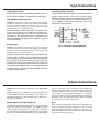
HTA125A/250A
Power Amplifiers
Installation & Use Manual
Specifications subject to change without notice.
© 2010 Bogen Communications, Inc.
All rights reserved. 54-5832-04B 1011
NOTICE: Every effort was made to ensure that the information in this guide was complete
and accurate at the time of printing. However, information is subject to change.
WARNING: To reduce the risk of Fire or Electric Shock, Do Not Expose this apparatus
to rain or moisture.
Apparatus shall not be exposed to dripping or splashing and no objects filled with liquids,
such as vases shall be placed on the apparatus.
WARNING: Only connect unit to AC mains outlet providing protective earthing connection.
NOTE: Mains plug is used as disconnect device from the mains and shall remain readily
accessible and operable.
CAUTION: These servicing instructions are for use by qualified service personnel only. To reduce the
risk of electric shock, do not perform any servicing other than that contained in the operating
instructions unless you are qualified to do so.
CAUTION: DO NOT INSTALL OR PLACE THIS UNIT IN A BOOKCASE, BUILT-IN CABINET, OR IN
ANOTHER CONFINED SPACE. ENSURE THE UNIT IS WELL VENTILATED. TO PREVENT THE RISK
OF SHOCK OR FIRE HAZARD DUE TO OVERHEATING, ENSURE THAT CURTAINS AND ANY OTHER
MATERIALS DO NOT OBSTRUCT THE VENTILATION VENTS.
Always follow these basic safety precautions when installing and using the unit:
IMPORTANT SAFETY INSTRUCTIONS
1. Read these instructions.
2. Keep these instructions.
3. Heed all warnings.
4. Follow all instructions.
5. Do not use this apparatus near water.
6. Clean unit with dry cloth.
7. Do not block any ventilation openings. Install in accordance with the manufacturer's instructions.
8. Do not install near any heat sources such as radiators, heat registers, stoves, or other apparatus
(including amplifiers) that produce heat.
9. Do not defeat the safety purpose of the polarized or grounding-type plug. A polarized plug has two
blades with one wider than the other. A grounding-type plug has two blades and a third grounding prong.
The wide blade, or the third prong, are provided for your safety. If the provided plug does not fit into your
outlet, consult an electrician for replacement of the obsolete outlet.
10. Protect the power cord from being walked on or pinched particularly at plugs, convenience receptacles,
and the point where they exit from the apparatus.
11. Only use attachments/accessories specified by the manufacturer.
12. Unplug this apparatus during lightning storms or when not used for long periods of time.
13. Refer all servicing to qualified service personnel. Servicing is required when the apparatus has been
damaged in any way, such as power-supply cord or plug is damaged, liquid has been spilled or objects
have fallen into the apparatus, the apparatus has been exposed to rain or moisture, does not operate
normally, or has been dropped.
CAUTION
RISK OF ELECTRIC SHOCK
DO NOT OPEN
CAUTION: TO PREVENT THE RISK OF ELECTRIC
SHOCK, DO NOT REMOVE ANY FRONT/BACK COVERS
OR PANELS. NO USER-SERVICEABLE PARTS INSIDE.
REFER SERVICING TO QUALIFIED PERSONNEL.
The lightning flash with arrowhead symbol, within an equilateral triangle, is intended to alert the user to the presence of
uninsulated "dangerous voltage" within the product's enclosure that may be of sufficient magnitude to constitute a risk
of electric shock to persons.
The exclamation point within an equilateral triangle is intended to alert the user to the presence of important
operating and maintenance (servicing) instructions.
Panel Diagrams
FRONT PANEL
HTA125A/250A
1
1. Overload Shut Down Indicator
REAR PANELS
HTA125A
3
6
2
7
5
2
1. Power Cord:
Ground Pin Connected to Chassis
2. 120V AC Outlet
(Not Switched)
1
2. ON/OFF Power Switch
4
1
HTA250A
2
3. AC Line Fuses
4. Output Connections
5. Balanced Input
(Accessory Transformer Required)
7
3
4
6
6. Unbalanced Input
7. Input Level Adjustment
5
Description
The Bogen HTA125A and HTA250A Series Power Amplifiers
are high performance units. MOSFET technology delivers distortion-free power into reactive loads, such as high-performance
loudspeakers or transformers.
The amplifiers are thermally protected to prevent damage due to excessive temperatures. The unique self-protecting output stage prevents thermal runaway which is often encountered in conventional
amplifiers.
The HTA125A supplies 125 watts (HTA250A supplies 250 watts)
continuous RMS output at less than 0.5% total harmonic distortion, with a frequency response of ±1 dB from 20 Hz to 20 kHz.
Electric shutdown circuitry is activated if an overload or short occurs and a front panel OVERLOAD SHUTDOWN LED illuminates.
Once the cause has been rectified, the unit automatically resets.
The power ON/OFF switch, located on the front panel, illuminates
when power is ON. The rear panel contains an Input Level control,
Input and Output connections, AC Line Fuse, and an Auxiliary Receptacle. A Low-Cut Filter switch is located internally on the printed
circuit board.
An input signal of only 500mV is required for full rated output
(150mV for low-impedance balanced input with Model TL600 accessory transformer). Input impedances are high-impedance unbalanced and low-impedance balanced (with TL600 accessory
transformer). Outputs include 4-ohm, 8-ohm, 25V (combined with
4-ohm output in HTA125A), 25VCT, and 70V. Line-bridging may
be achieved with Bogenʼs TL100 accessory (transformer).
Installation
Rack Mounted Installation
Power and Grounding
The amplifier is designed for installation in a standard 19” equipment rack. Position the unit in the rack and secure with screws
through the amplifier front panel.
The AC line cord has a 3-prong plug which should be plugged into
a 3-wire grounded, 120V AC, and 60 Hz outlet. It is important to
ground the amplifier.
NOTE: Before placing the amplifier in a rack, install any accessory
transformers required.
Auxiliary Power Receptable
Ventilation
Caution: The front panel ON/OFF switch does not control the
auxiliary receptacle.
The amplifier generates heat during operation. It must be properly ventilated to prevent excessive temperature rise. If other heatproducing equipment, or several amplifiers have been installed in
an enclosed rack or cabinet, you must ensure that there is space
above and below the amplifier(s) to allow for passive cooling. It is
recommended that the amplifier be installed on the bottom of a
rack or above any equipment that does not produce heat.
The auxiliary power receptacle on the rear panel is a 3-wire
grounded outlet and may be used to supply power to accessory
equipment in the sound system. Ensure that the accessory equipment does not require more than 300 watts. Equipment connected
to the auxiliary receptacle with a 3-prong line cord will be grounded,
providing the amplifier line cord has been properly grounded.
Input Connections
High-Impedance Input
A high-impedance input is provided by two RCA type jacks.
An input signal of 500mV is required for full rated output.
Low-Impedance Balanced Input
Caution: To avoid electric shock, be sure to disconnect AC Power
Cord before removing the cover of the amplifier unit. DO NOT
perform any function requiring the removal of the cover of the
amplifier unless you are qualified to do so.
A balanced input, provided at the BAL LO-Z terminal strip,
requires the installation of a TL600 line-matching transformer. Remove the top cover of the unit and install the
transformer in the socket designated T1 provided on the
printed circuit board. An input signal of 150mV is required
for full rated output.
Input from Another Amplifier
The HTA125A/HTA250A amplifiers may be driven from an
amplifier that provides a 25V or 70V speaker output.
Connect the output of the driver amplifier to the HI-Z INPUT
jacks via a resistor network. The resistors shown in Fig. 1
are in addition to the normal loudspeaker load on the
output of the driver amplifier.
R1
OUTPUT
TERMINAL
STRIP OF
DRIVER
AMPLIFIER
70V
R2
100
1/2W
GND
TO HIGH
IMPEDANCE
INPUT OF
POWER
AMPLIFIER
AT 70V R1 = 10K, 1/2W
AT 25V R1 = 3.3K, 1/2W
Bridging Input
Fig. 1- Input From Another Amplifier
Caution: To avoid electric shock, be sure to disconnect AC Power
Cord before removing the cover of the amplifier unit. DO NOT
perform any function requiring the removal of the cover of the
amplifier unless you are qualified to do so.
The inputs of two or more amplifiers may be paralleled without loss of gain. To do this, install a TL100 transformer (for
up to 6 amplifiers) in the transformer socket designated T1
on the printed circuit board. Connect the signal source to
the BAL LO-Z terminal strip on the rear panel. Use the two
outside terminals on the input terminal strip and connect the
cable shield to the GND terminal. If an unbalanced input is
required, connect a jumper wire from the GND terminal to
an adjacent input terminal.
Output Connections
Caution: Follow local electrical codes when connecting amplifier
output.
Output connections are available on the rear panel terminal strip
for 4-ohm, 8-ohm, 25V, 25VCT, and 70V (the 4-ohm output is combined with the 25V tap on the HTA125A). Class 2 wiring is acceptable for output loads.
strip are connected using a shorting clip. The shorting clip
enables the amplifier output to act as an unbalanced output (one
side of the output connected to ground). If desired, the output
can be made to be a balanced output with no connection to
ground. To balance the output, simply remove the shorting clip.
All speaker connections remain the same as above. 25V speaker
connections are done in the same manner.
Speaker Matching & Power Distribution
Hum
The HTA125A and HTA250A feature output connectors for 4-ohm,
8-ohm, 25V, 25VCT and 70V speakers. The amplifiers provide
outputs for 25V and 70V speakers. 70-volt speaker connections
are made between the 70V and COM terminals on the output
terminal strip. The COM and GND terminals of the output terminal
If the connections between the signal sources and amplifier are
incorrect or defective, hum-type interference may occur. Check
for proper grounding, broken wires, shields, poor connections, etc.
Keep input cables away from speaker cables and away from
transformers and AC power lines.
Operation
Power
Overload Shutdown Indicator
The power switch applies power to the amplifier; it does not control any associated equipment which may be connected to the
auxiliary power receptacle on the rear panel. The POWER
SWITCH illuminates when power has been applied to the unit.
Electronic shutdown circuitry activates whenever an overload or
short occurs on the output of the amplifier. The front panel OVERLOAD SHUTDOWN LED illuminates indicating the discontinuation of power output; once the cause has been determined and
rectified, the unit automatically resets.
Low-Cut Filter Switch
Caution: To avoid electric shock, be sure to disconnect AC Power
Cord before removing the cover of the amplifier unit. DO NOT
perform any function requiring the removal of the cover of the
amplifier unless you are qualified to do so.
The Low-Cut Filter Switch designated SW1 is located next to the
transformer socket on the printed circuit board and is accessible
by removing the top cover of the amplifier. The switch provides
10 dB attenuation at 100 Hz.
Input Level Control
The input level control, located on the rear panel, adjusts the input
signal applied to the amplifier. Turn the adjustable screw clockwise to increase the level.
Warning: Many loudspeakers may be damaged if overdriven.
Therefore, always begin system setup with the input level control
fully counterclockwise and gradually increase the setting to obtain the desired output level.
Thermal Cut-Out
The amplifier is protected by a thermal cut-out which should not
trip under normal conditions. If it trips, check for inadequate ventilation of the unit or overloading. The cut-out will automatically
reset after cooling.
AC Line Fuse
Replace the fuse only with same type rating. If a second fuse
blows, do not make any attempt to operate the unit. Consult the
Bogen Service Department or an authorized service agency.
Technical Specifications
Rated Output Power:
Total Harmonic Distortion:
Frequency Response:
Input Sensitivity:
Hum and Noise:
Outputs:
Output Regulation:
Input Impedances:
Low-Cut Filter:
Controls & Indicators:
Power Requirements:
Thermal Emissions (full power):
Overload Protection:
Auxiliary Receptacle (not switched):
Dimensions (without removable feet):
Front Panel Dimensions:
Finish:
Shipping Weight:
Regulatory Approvals:
Accessories:
HTA125A: 125W; HTA250A: 250W
Less than 0.5%, 20 to 20,000 Hz at full rated output
±1 dB, 20 to 20,000 Hz at full rated output
Hi-Z, 500mV; Lo-Z balanced, with optional transformer, 150mV
90 dB below rated output
4 ohms, 8 ohms, 25V, 25VCT, 70V
Better than 2 dB from no load to full load
Hi-Z, 50k ohms unbalanced; Lo-Z, 600 ohms, balanced or unbalanced,
and 1:1 bridging with optional plug-in transformers
-10 dB @ 100 Hz
Front Panel — Illuminated On/Off power switch and overload shutdown LED
Rear Panel — Input level control, Slo-Blo fuse
Internal — Low-Cut filter switch
HTA125A: 120V ~, 60 Hz, 3.1A, 260 watts @ Full Rated Output (Idle 45W)
HTA250A: 120V ~, 60 Hz, 5.5A, 520 watts @ Full Rated Output (Idle 60W)
HTA125A: 426.9 BTU/hr.; HTA250A: 939.2 BTU/hr
Electronic overload protection
Electrical: HTA125A: 4A Slo-Blo Fuse; HTA250A: 7A Slo-Blo Fuse
Thermal: Thermostat
Three-wire grounded*, 300 watts maximum
19" W x 5-1/4" H x 11" D (48.3 x 13.3 x 27.9 cm)
19" W x 5-1/4" H (48.3 x 13.3 cm)
Black
HTA125A: 44 lbs.; HTA250A: 56 lbs.
ETL listed
Model TL600, 600-ohm line-matching transformer; Model TL100,
1:1 line-matching transformer
*This receptacle will be grounded only if the power amplifier has been grounded properly.
Limited Warranty; Exclusion of Certain Damages
The Bogen HTA125A & HTA250A Power Amplifiers are warranted to be free from defects in material and workmanship for two (2) years from
the date of sale to the original purchaser. Any part of the product covered by this warranty that, with normal installation and use,
becomes defective (as confirmed by Bogen upon inspection) during the applicable warranty period, will be repaired or replaced by Bogen, at
Bogenʼs option, provided the product is shipped insured and prepaid to: Bogen Factory Service Department, 50 Spring Street, Ramsey, NJ 07446,
USA. Repaired or replacement product will be returned to you freight prepaid. This warranty does not extend to any of our products that have
been subjected to abuse, misuse, improper storage, neglect, accident, improper installation or have been modified or repaired or altered in any
manner whatsoever, or where the serial number or date code has been removed or defaced.
THE FOREGOING LIMITED WARRANTY IS BOGENʼS SOLE AND EXCLUSIVE WARRANTY AND THE PURCHASERʼS SOLE AND
EXCLUSIVE REMEDY. BOGEN MAKES NO OTHER WARRANTIES OF ANY KIND, EITHER EXPRESS OR IMPLIED, AND ALL IMPLIED
WARRANTIES OF MERCHANTABILITY OR FITNESS FOR A PARTICULAR PURPOSE ARE HEREBY DISCLAIMED AND EXCLUDED TO
THE MAXIMUM EXTENT ALLOWABLE BY LAW. Bogen's liability arising out of the manufacture, sale or supplying of products or their use or
disposition, whether based upon warranty, contract, tort or otherwise, shall be limited to the price of the product. IN NO EVENT SHALL BOGEN
BE LIABLE FOR SPECIAL, INCIDENTAL OR CONSEQUENTIAL DAMAGES (INCLUDING, BUT NOT LIMITED TO, LOSS OF PROFITS,
LOSS OF DATA OR LOSS OF USE DAMAGES) ARISING OUT OF THE MANUFACTURE, SALE OR SUPPLYING OF PRODUCTS, EVEN IF
BOGEN HAS BEEN ADVISED OF THE POSSIBILITY OF SUCH DAMAGES OR LOSSES. Some States do not allow the exclusion or limitation of incidental or consequential damages, so the above limitation or exclusion may not apply to you. This warranty gives you specific legal rights,
and you may also have other rights which vary from State to State.
Products that are out of warranty will also be repaired by the Bogen Factory Service Department – same address as above or call 201-934-8500.
The parts and labor involved in these repairs are warranted for 90 days when repaired by the Bogen Factory Service Department. All shipping
charges in addition to parts and labor charges will be at the owner's expense. All returns require a Return Authorization number. For most
efficient warranty or repair service, please include a description of the failure.
12/2008
50 Spring Street, Ramsey, NJ 07446, U.S.A.
Tel. 201-934-8500 • Fax: 201-934-9832
www.bogen.com