1
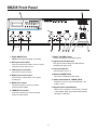
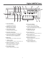
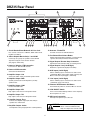
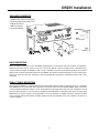
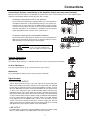
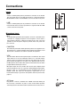
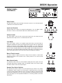
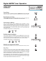
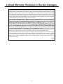
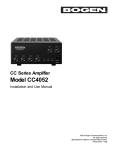
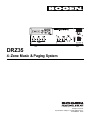
DRZ35
4 - Zone Music & Paging System
© 2009 Bogen Communications, Inc.
All rights reserved.
Specifications subject to change without notice.
54-2190-01B 0912
NOTICE: Every effort was made to ensure that the information in this guide was complete
and accurate at the time of printing. However, information is subject to change.
WARNING: To reduce the risk of Fire or Electric Shock, Do Not Expose this apparatus
to rain or moisture.
Apparatus shall not be exposed to dripping or splashing and no objects filled with liquids,
such as vases shall be placed on the apparatus.
WARNING: Only connect unit to AC mains outlet providing protective earthing connection.
NOTE: Mains plug is used as disconnect device from the mains and shall remain readily
accessible and operable.
CAUTION: These servicing instructions are for use by qualified service personnel only. To reduce the
risk of electric shock, do not perform any servicing other than that contained in the operating
instructions unless you are qualified to do so.
Always follow these basic safety precautions when installing and using the unit:
IMPORTANT SAFETY INSTRUCTIONS
1.
2.
3.
4.
5.
6.
7.
8.
Read these instructions.
Keep these instructions.
Heed all warnings.
Follow all instructions.
Do not use this apparatus near water.
Clean unit with dry cloth.
Do not block any ventilation openings. Install in accordance with the manufacturer's instructions.
Do not install near any heat sources such as radiators, heat registers, stoves, or other apparatus
(including amplifiers) that produce heat.
9. Do not defeat the safety purpose of the polarized or grounding-type plug. A polarized plug has two
blades with one wider than the other. A grounding-type plug has two blades and a third grounding prong.
The wide blade, or the third prong, are provided for your safety. If the provided plug does not fit into your
outlet, consult an electrician for replacement of the obsolete outlet.
10. Protect the power cord from being walked on or pinched particularly at plugs, convenience receptacles,
and the point where they exit from the apparatus.
11. Only use attachments/accessories specified by the manufacturer.
12. Unplug this apparatus during lightning storms or when not used for long periods of time.
13. Refer all servicing to qualified service personnel. Servicing is required when the apparatus has been
damaged in any way, such as power-supply cord or plug is damaged, liquid has been spilled or objects
have fallen into the apparatus, the apparatus has been exposed to rain or moisture, does not operate
normally, or has been dropped.
CAUTION
RISK OF ELECTRIC SHOCK
DO NOT OPEN
CAUTION: TO PREVENT THE RISK OF ELECTRIC
SHOCK, DO NOT REMOVE ANY FRONT/BACK COVERS
OR PANELS. NO USER-SERVICEABLE PARTS INSIDE.
REFER SERVICING TO QUALIFIED PERSONNEL.
The lightning flash with arrowhead symbol, within an equilateral triangle, is intended to alert the user to the presence
of uninsulated "dangerous voltage" within the product's
enclosure that may be of sufficient magnitude to constitute
a risk of electric shock to persons.
The exclamation point within an equilateral triangle is
intended to alert the user to the presence of important
operating and maintenance (servicing) instructions.
Contents
Page
DRZ35 FRONT PANEL ........................................................................................................................2
DIGITAL AM/FM TUNER ......................................................................................................................3
DRZ35 REAR PANEL ............................................................................................................................4
DRZ35 INSTALLATION..........................................................................................................................5
CONNECTIONS ................................................................................................................................6-8
DRZ35 OPERATION ............................................................................................................................9
DIGITAL AM/FM TUNER OPERATION ..............................................................................................10
SPECIFICATIONS ..............................................................................................................................11
DRZ35 BLOCK DIAGRAM ................................................................................................................12
LIMITED WARRANTY..........................................................................................................................13
1
DRZ35 Front Panel
1
2
3
12
4
5
6
7
8
9
10
7. Master VOLUME Control
1. Digital AM/FM Tuner
Controls overall level of mixed input signals.
AM/FM tuner module (see Page 3 for details).
8. Signal Level LED Indicators
2. MIC Input Level Control
Five-segment output voltage level. 0dB indicates
maximum rated output level.
Controls microphone level. MIC can be set so that
it will mute all other input sources.
9. Power ON Indicator
3. LINE Input Level Control
Indicates when Power is on.
Controls level of the Line input.
10. Master POWER Switch
4. MUSIC Input Level Control
Turns Power to DRZ35 unit ON or OFF.
Controls level of selected music source (Tuner
or AUX input).
11. Music Select Buttons: TUNER & AUX
Determines if Tuner or rear panel AUX input is fed
to Music control.
5. BASS Tone Control
Controls the amount of cut or boost of Bass
frequencies below 100Hz.
12. Speaker Zone Select Buttons
Allows zones of speakers to be selectively connected
to the amplifier output. Push-On/Push-Off operation
(see page 4, callout #2).
6. TREBLE Tone Control
Controls the amount of cut or boost of Treble
frequencies above 10kHz.
2
11
Digital AM/FM Tuner
13
14
15
16
1
2
4
3
5
12
11
10
9
8
1. Tuner Power Button
7
6
10. Tuning Units Display
Turns Digital Tuner ON or OFF.
Indicates receiving frequency units.
2. AM/FM Band Select Button
11. Channel Frequency/Sleep Display
Selects AM or FM tuning bands.
Shows current channel frequency or sleep time.
12. FM/AM Band Indicator
3. Channel Memory Button
Indicates receiving band.
Used when storing preset channels.
13. Sleep Indicator Icon
4. Sleep Mode Select Button
Turns on to indicate sleep function has been set.
Used to set turn-off delay time of the tuner section.
14. Stereo Indicator Icon
5. Channel Select Buttons: UP and DOWN
Indicates when received station is in stereo.
Manual station tuning UP and DOWN buttons.
15. Memory Indicator Icon
6. Memory Up
Turns on to indicate that a station preset is
ready to be stored.
Press to change to the next higher station preset.
7. +5 Memory Offset
Used in tandem with 1- 5 buttons to select presets 6 - 10.
16. Channel Indicator Icon
Indicates channel/preset in use.
8. Station Preset Buttons: 1-5 (6 - 10)
Selects a preset station from 1 to 5 directly
(6 to 10 using the +5 button in tandem).
9. Preset Station Display
Indicates currently selected preset station.
3
DRZ35 Rear Panel
3
2
4
CAUTION
RISK OF ELECTRIC SHOCK
DO NOT OPEN
WARNING:
TO REDUCE THE RISK OF FIRE OR ELECTRICAL SHOCK,
DO NOT EXPOSE THIS UNIT TO RAIN OR MOISTURE.
AVIS:
RISQUE DE CHOC ELECTRIQUE NE PAS OUVRIR.
1
5
6
7
8
9 10 11
1. Circuit Breaker/Reset Button & AC Line Cord
13
14
15
16
17 18
19
12. Antenna: 75-ohm/FM
Line cord for connection to 120V AC, 60Hz outlet. Circuit
breaker reset button.
2. 4-Zone Outputs Barrier Strip:
12
Co-axial connector for 75Ω FM antenna.
13. Pre-Volume/Post Volume Button
+ and COM
Switch position determines whether or not the Booster
signal is affected by the Master Volume Control.
Connect up to 4 groups of speakers to this terminal
strip when using the zone selection function
(see page 2, callout #12).
14. Signal Output: Booster Amp Connection
Signal level feed to Booster amp or recording device.
3. Antenna: 300-ohm / FM Connection
15. Signal Output: Line (Left & Right)
Connection for 300-ohm FM antenna.
Dual-mono, signal level output (Pre-Volume).
4. Antenna: AM Connection
16. AUX Inputs (Left & Right)
Connection for AM antenna.
Stereo combining input connections for audio source
controlled by Music Select switch (AUX selection) and
Music Level Control (see page 2, callout #4).
5. Amplifier Output: Link
Set Link for either 4-ohm or 25V/70V speaker loads.
17. Line Inputs (Left & Right)
6. Amplifier Output: GND
Stereo combining input connections for audio source
controlled by Line Level Control.
System ground used for low-impedance (4-ohm)
speaker loads.
18. Phantom OFF/Phantom ON Button
7. Amplifier Output: COM
Turns Phantom power for condenser Mics on and off.
Used for 25V/70V loads.
19. VOX ON/OFF Switch
8. Amplifier Output: 25V
Turns voice-activated muting of Music & Line inputs by
the microphone on or off.
Amp output connections for 25V speaker loads.
9. Amplifier Output: 70V
20. MIC Input Connection
Amp output connections for 70V speaker loads.
XLR style microphone input connector.
10. Amplifier Output: Zone
Connects the amplifier output (4Ω, 25V, 70V) to
speaker zone switch bank.
WARNING: 4-ohm and 25V/70V outputs should
11. Amplifier Output: 4-ohm
not be connected simultaneously.
Only one output to be used at a time.
Low-impedance amp output (4Ω min. load impedance).
4
20
DRZ35 Installation
PACKAGE CONTENTS
1. DRZ35 4-Zone Music & Paging Unit
2. Rack Mounting Brackets with screws
3. FM Dipole Antenna
4. AM Loop Antenna
1
5. Instruction Manual
5
4
3
2
RACK MOUNTING
When assembling equipment in a rack, the DRZ35 should either be on the bottom of the rack or above any equipment
that does not produce heat to ensure a source of cool air to the bottom of the unit. Provide at least 1 RU (Rack Unit)
of space above and below the DRZ35 so that cool air is available to the unit. Rack mounting brackets are provided
with the unit. To attach rack mounting brackets to the DRZ35, first remove and discard the three screws located toward
the front on each side of the unit. Using the screws included with the rack brackets, attach the brackets to each side
of the unit.
SHELF / TABLE MOUNTING
When placing the DRZ35 on a shelf or table, the unit should ideally stand alone with no equipment on top of or beneath it.
If the DRZ35 must be stacked with other equipment, care must be taken to ensure that the DRZ35, which is passively
cooled, be allowed a minimum clearance of 1/2” for the bottom (set by height of the unitʼs feet) and a minimum of 1” from
the top to other obstructions. Be sure that any equipment situated below the unit produces little heat. The sides of the
DRZ35 have no specific clearance area requirements. These are minimum acceptable clearances, however the more
space provided, both top and bottom, the better. Rubber feet must be installed on the unit to allow it to be placed on
a shelf or tabletop.
5
Connections
Connecting Speakers to the Zone Switch Bank
The terminal strip in the Zone Output section of the rear panel allows groups of speakers to be connected to a selector switch
bank so that they can be selectively connected and disconnected to the DRZ35ʼs amplifier. This feature is useful when paging
into only one area or a few areas is desired. The user selects the zones to be paged, makes the page, and then can select
different zones to get background music.
Wiring Groups of Speakers Together:
Each group or zone of speakers are connected by the + and COM terminals
for each zone. For best sound performance, the speakers should be wired
consistently. All the Black or Com wires for transformer coupled speakers in
a group should be wired together and all the transformer Tap wires should
be wired together. The Com and Tap leads from the group of speakers should
then be wired to the COM and + terminals (respectively) of the particular
zone output on the DRZ35. Other zones of speakers should be wired likewise.
Care should be taken to ensure that the sum of all the speakers in the zones
does not exceed 35W, in case all zones are turned on at once.
Low-impedance speakers can be wired to the zone terminals, however, the
combined load of all the speakers when all zones are turned on must not be
less than 4 ohms. The amplifier is not designed to drive loads lower than
4 ohms. Meeting this requirement is often difficult to do with low-impedance speakers and calculations using Ohmʼs law are typically required if
more than one or two speakers are used per zone.
Consistency in wiring low-impedance speakers should also be exercised. One of the speaker terminals is typically
identified by a + symbol, a red dot, or some other identifier. All the terminals in a zone should be wired together and
returned to the + of the zoneʼs terminals. Likewise for the other terminal on the speakers.
Reversing the speaker connection on one speaker versus another will not damage the speaker or the DRZ35, but
it may reduce the amount of bass that the system will produce since the reversed speaker will cancel some of the
bass from the adjacent speakers.
WARNING: DO NOT mix different speaker types (4Ω, 70V, and 25V) in the same system.
Connecting the Speaker Zone Switch Bank to the Amplifier Output:
As mentioned in the previous section, the zone selector is simply a bank of switches that can direct the DRZ35ʼs amplifier to
different groups of speakers. Before the zone section function can operate, it must be connected to one of the amplifier output
types. A jumper wire is used to connect the ZONE terminal on the Amplifier Outputs terminal strip to either the 25V, 70V or
4-ohm terminal on the same strip.
Using Transformer-Coupled Speakers:
When using transformer-coupled speakers, use the included jumper to
connect the ZONE terminal to either 25V or 70V depending on the speakers
being used. Also make sure that a jumper is connected across the LINK
terminals. A second jumper is typically installed across the GND and COM
terminals. This jumper is optional when using transformer-coupled speakers.
In some instances it is desirable to allow the transformer-coupled speakers to
float and not have a connection to the systemʼs ground. The GND to COM
jumper can be omitted if desired, but typically it is put in place.
Jumpers shown connecting the 70V
Output to the Zone Selection Switches.
Using Low-Impedance Speakers:
When using low-impedance speakers, use an included jumper to connect the
ZONE terminal to the 4Ω terminal and a jumper to connect the GND and
COM terminals on the Amplifier Output terminal strip. Also be sure to remove
any jumper connected across the LINK terminals. Removing the link jumper
will disconnect the output transformer from the DRZ35ʼs amplifier.
6
Jumpers shown connecting the 4Ω
Output to the Zone Selection Switches.
Connections
Connecting a Speaker Load directly to the Amplifier Output (not using zone function):
When the zone selection feature is not desirable, the speaker load can be connected directly to one of the amplifier output
terminals on the Amplifier Output terminal strip (25V, 70V or 4-ohm).
Connecting a single group of 25V or 70V speakers:
The speaker load for transformer-coupled speakers are connected between
the COM and either 25V or 70V terminal depending on the speaker type.
A jumper must be connected across the LINK terminals for these outputs
to work. A second jumper is typically connected across the GND and COM
terminals. This jumper can be omitted if it is desirable to have the speaker
signals float without a hard connection to the system ground.
Connecting a single group of low-impedance speakers:
The speaker load for low-impedance speakers are connected between the
GND and the 4Ω terminal. There must be no jumper installed across the
LINK terminals for the 4-ohm output to work properly.
WARNING: 4-ohm and 25V/70V outputs should
not be connected simultaneously.
Only one output to be used at a time.
Antenna Connections:
300-ohm / FM Antenna The included di-pole antenna or a 300-ohm antenna feed can be connected to these terminals.
75-ohm / FM Antenna A 75-ohm coaxial antenna can be connected to this F style connector.
AM Antenna The included AM loop antenna can be connected to these terminals
Signal Outputs:
• BOOSTER AMP OUTPUT
A mono RCA connector provides a line level output of the signal feeding the
DRZ35 power amplifier. This signal is typically used to feed the input of an additional
booster amp for systems that require more than the DRZ35ʼs 35 watts of power.
Since the additional booster amp is external to the DRZ35, the zone switches have
no effect on the output of this amp. The Booster Amp Output is affected by the
PRE/POST Volume switch, which allows the installer to determine if the Booster
Amp signal is affected by changes in the front panel volume control (Post Volume)
or not (Pre Volume). When using this output to supply an additional external amplifier,
the Post position might be desirable so that the output level of that amplifier
tracks adjustments to the DRZ35 volume control. If it is desirable to use the
volume control on the external booster amp to control its output level, then Pre
Volume should be used so that the input level to the booster amp does not change
with adjustments to the front panel volume control of the DRZ35.
• LINE OUTPUT
The LINE Output is a dual-mono feed of the DRZ35ʼs output for use with recording
devices or other amplifiers. The LINE Output is always Pre Volume.
7
Connections
Inputs:
• AUX
A stereo combining RCA pair are provided for connection of an external
line level audio device. The AUX input works in conjunction with the
MUSIC SELECT switch and the MUSIC control on the unitʼs front panel.
• LINE
A stereo combining RCA pair are provided for connection of an external
line level audio device. The line input works in conjunction with the LINE
control on the unitʼs front panel.
Microphone Input:
• MIC
A standard XLR type balanced microphone connector is provided for the
connection of a paging microphone. The microphone can be either a
low impedance Dynamic or Electret Condenser type. The connection
polarities for the microphone input are printed on the rear panel near
the connector.
• PHANTOM
The Phantom push button allows phantom power to be supplied to the
microphone if it is needed. Only Electret Condenser microphones need
this function. It should be set to OFF for dynamic microphones.
• VOX
The VOX switch allows the microphone input to override the other audio
inputs when it is in use. By setting the switch to on, any audio activity
detected at the microphone input will mute the audio from the other
inputs until the microphone is no longer in use. With the VOX set to off,
the Microphone will not mute other inputs but instead mix into the audio
program with the other input sources.
Microphone inputs are very sensitive and can pick up the slightest audio
from the microphone. This can cause false signal triggering VOX muting.
Because of this, it is recommended to use a microphone that has an
ON/OFF switch that quiets the microphoneʼs output when it is off.
Push-to-talk desktop or gooseneck microphones work very well for this
purpose.
• AC Power
Plug the line cord into a standard 15A, 120VAC outlet after making all
the necessary connections. A push to reset circuit breaker provides
overload protection. Reset this breaker should the unit ever fail to turn on.
8
DRZ35 Operation
FRONT PANEL
CONTROLS:
Power Switch
The large power switch in the lower right corner turns the unit on or off. The ON indicator
confirms the current state of the switch.
Input Level Controls
Separate input level controls are provided for Microphone, Line, and Music inputs.
Use these 3 controls to set the desired audio levels between the three sources.
Volume Control
The large Volume control sets the overall system output level. The relative mix level
between the three input sources is not affected by this control.
Level Meter
Next to the Volume control is a 5-segment output level meter. This meter helps in
setting the maximum level of the system. During loud passages of audio, the output meter
should not exceed the 0 dB segment. When this segment is on, the output from
the amp has reached its designed maximum output voltage level. Generally exceeding this
level can cause noticeable distortion in the audio program and exceeding this level continuously may cause temporary thermal shut down of the amp as a protection measure.
If the system output level is very low, the level meter may not light any segments.
Bass & Treble Controls
Use these controls to adjust the amount of high and low frequency content heard
through the speakers. The 0 position on the control provides no cut or boost to that
frequency band.
Music Select Switch
Use the Music Select switch to choose between feeding the Tuner signal or the rear
panel AUX input signal to the Music Input. Use the Music Input Level control to adjust
the relative volume of the selected input signal.
Speaker Zone Select Switches
The Speaker Zone Select switches are push-on/push-off type switches. Any number
or combination of these switches can be selected to control which zones in the facility
receive the audio program. When the zone is selected, the button is sunken flush with
the front panel. When the zone is not selected, the button noticeably protrudes from the
panel. See Page 6 for more important information on connecting speakers to the Zone
Switch Bank.
9
Digital AM/FM Tuner Operation
TUNER PANEL
CONTROLS:
Power Button
If the tuner section is currently off, press the POWER button to turn on the Tuner
module. The Tuner module can be turned off separately from the main power button.
Band Selection and Tuning
Push the BAND button until the desired band (AM or FM) is shown in the display. Then
use the DOWN and UP buttons to manually tune to the desired station.
Storing stations in Memory
Tune to a desired station, press the MEMORY button (the MEM icon will be
displayed) and then immediately push the desired memory button (1-5). The tuner
allows up to 10 stations to be stored for each band. To store a station in memory locations 6 through 10, press the memory button, then the +5 button, and then one of
the 1-5 memory buttons. The memory location in these cases is 5+ the number of the
memory button used.
For example, memory location 7 is stored by pressing:
>
>
Recalling stations from Memory
First select the desired band (AM/FM) by using the BAND button. Then press the
desired memory number (1-5). To access stations stored in memory locations 6-10, first
push the +5 button and then the memory button (1-5) so that it adds up to the
desired memory location. See the example above for how to use the +5 button.
For example, memory location 7 is recalled by pressing:
>
>
>
Manually scan through stored stations
Repeatedly pushing the ME-UP button will sequence through all the memory locations.
Sleep Timer
The tuner can be set to turn off after a preset number of minutes. To turn on this
function and set the turn off delay, repeatedly press the SLEEP button. The display
will show the number of minutes until the tuner turns off. The delay time starts at 90
minutes and will change (at 10 minute increments) with each push of the SLEEP
button and eventually return to off (the sleep function is disabled).
Once the tuner turns off due to the sleep timer, it must be turned on again by pressing the POWER button on the Tuner module. Please note that the sleep function only
affects the tuner module and does not turn off the DRZ35 itself. Microphone paging
and other inputs will still be heard when the tuner is off.
10
Specifications
Amplifier
Power Rating (RMS): . . . . . . . . . . . . . . . . . . . . . . .35 watts
Distortion: . . . . . . . . . . . . . . . . . . . . . . . . . . . . . . . .<1% Rated output power @ 1 kHz
Signal to Noise Ratio: . . . . . . . . . . . . . . . . . . . . . .MIC: -55 dB
LINE/AUX: -70 dB
Audio Frequency Response: . . . . . . . . . . . . . . . .70 Hz - 15 kHz (25/70V)
20 Hz - 20 kHz (4Ω)
Speaker Outputs: . . . . . . . . . . . . . . . . . . . . . . . . . .4-ohm, 25V, 70V
Tone Controls: . . . . . . . . . . . . . . . . . . . . . . . . . . . .Bass: +/-10 dB @ 100 Hz
Treble: +/-10 dB @ 10 kHz
Microphone Input: . . . . . . . . . . . . . . . . . . . . . . . . .750 μV/1k-ohm balanced (3-pin XLR connector)
Phantom Power: . . . . . . . . . . . . . . . . . . . . . . . . . . .21V (switch-enabled)
MIC Precedence: . . . . . . . . . . . . . . . . . . . . . . . . . .VOX-triggered (switch-enabled)
LINE and AUX Inputs: . . . . . . . . . . . . . . . . . . . . . .80 mV/10k-ohm unbalanced; RCA jack
Booster Amp Output: . . . . . . . . . . . . . . . . . . . . . . .50Ω / Pre (1V), Post (4V); RCA jack
Line Output: . . . . . . . . . . . . . . . . . . . . . . . . . . . . . .50Ω / (1V); RCA jack
Tuner
Station Tuning: . . . . . . . . . . . . . . . . . . . . . . . . . . . .Digital, pushbutton, with PLL Synthesizer
Band Coverage: . . . . . . . . . . . . . . . . . . . . . . . . . . .AM: 522 to 1620 kHz
FM: 87.5 to 108 MHz
Antenna: . . . . . . . . . . . . . . . . . . . . . . . . . . . . . . . . .75Ω coaxial, 300Ω screw, AM Loop screw
Preset Memory: . . . . . . . . . . . . . . . . . . . . . . . . . . .10 FM, 10 AM
Memory Scan: . . . . . . . . . . . . . . . . . . . . . . . . . . . . .Preset stations
Channel Indicator: . . . . . . . . . . . . . . . . . . . . . . . . .Backlit, LCD
Power / Dimensions
Power Required: . . . . . . . . . . . . . . . . . . . . . . . . . . .120V AC nominal @ 60 Hz
Power Consumption: . . . . . . . . . . . . . . . . . . . . . . .98W
Dimensions: . . . . . . . . . . . . . . . . . . . . . . . . . . . . . .17" W x 5-1/4" H x 13-5/8" D
Product Weight: . . . . . . . . . . . . . . . . . . . . . . . . . . .27 lbs.
Regulatory Approvals: . . . . . . . . . . . . . . . . . . . . . .UL, CUL, FCC
11
DRZ35 Block Diagram
12
Limited Warranty; Exclusion of Certain Damages
The Bogen DRZ35 4-Zone Music & Paging System is warranted to be free from defects in material and workmanship for two
(2) years from the date of sale to the original purchaser. Any part of the product covered by this warranty that, with normal
installation and use, becomes defective (as confirmed by Bogen upon inspection) during the applicable warranty period, will
be repaired or replaced by Bogen, at Bogen’s option, provided the product is shipped insured and prepaid to: Bogen Factory
Service Department, 50 Spring Street, Ramsey, NJ 07446, USA. Repaired or replacement product will be returned to you
freight prepaid. This warranty does not extend to any of our products that have been subjected to abuse, misuse, improper
storage, neglect, accident, improper installation or have been modified or repaired or altered in any manner whatsoever,
or where the serial number or date code has been removed or defaced.
THE FOREGOING LIMITED WARRANTY IS BOGEN’S SOLE AND EXCLUSIVE WARRANTY AND THE PURCHASER’S
SOLE AND EXCLUSIVE REMEDY. BOGEN MAKES NO OTHER WARRANTIES OF ANY KIND, EITHER EXPRESS OR
IMPLIED, AND ALL IMPLIED WARRANTIES OF MERCHANTABILITY OR FITNESS FOR A PARTICULAR PURPOSE ARE
HEREBY DISCLAIMED AND EXCLUDED TO THE MAXIMUM EXTENT ALLOWABLE BY LAW. Bogen's liability arising out
of the manufacture, sale or supplying of products or their use or disposition, whether based upon warranty, contract, tort or
otherwise, shall be limited to the price of the product. IN NO EVENT SHALL BOGEN BE LIABLE FOR SPECIAL, INCIDENTAL OR CONSEQUENTIAL DAMAGES (INCLUDING, BUT NOT LIMITED TO, LOSS OF PROFITS, LOSS OF DATA
OR LOSS OF USE DAMAGES) ARISING OUT OF THE MANUFACTURE, SALE OR SUPPLYING OF PRODUCTS, EVEN
IF BOGEN HAS BEEN ADVISED OF THE POSSIBILITY OF SUCH DAMAGES OR LOSSES. Some States do not allow the
exclusion or limitation of incidental or consequential damages, so the above limitation or exclusion may not apply to you. This
warranty gives you specific legal rights, and you may also have other rights which vary from State to State.
Products that are out of warranty will also be repaired by the Bogen Factory Service Department – same address as above
or call 201-934-8500. The parts and labor involved in these repairs are warranted for 90 days when repaired by the Bogen
Factory Service Department. All shipping charges in addition to parts and labor charges will be at the owner's expense. All
returns require a Return Authorization number. For most efficient warranty or repair service, please include a
description of the failure.
12/2008
13
50 Spring Street, Ramsey, NJ 07446, U.S.A.
Tel. 201-934-8500 • Fax: 201-934-9832
www.bogen.com