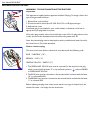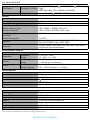
1
BDL6545AT www.publicsignagesolutions.philips.com EN User manual Cleaning and troubleshooting User Manual BDL6545AT SAFETY AND TROUBLESHOOTING INFORMATION Safety precautions and maintenance WARNING: Use of controls, adjustments or procedures other than those specified in this documentation may result in exposure to shock, electrical hazards and/or mechanical hazards. Read and follow these instructions when connecting and using your display: Operation: • Keep the display out of direct sunlight and away from stoves or any other heat sources. • Remove any object that could fall into the ventilation holes or prevent proper cooling of the display’s electronics. • Do not block the ventilation holes on the cabinet. • When positioning the display, make sure the power plug and outlet are easily accessible. • When turning off the display by detaching the power cord, wait for 6 seconds before re-attaching the power cord for normal operation. • Ensure the use of an approved power cord provided by Philips at all times. If your power cord is missing, please contact your local service center. • Do not subject the display to severe vibration or high impact conditions during operation. • Do not knock or drop the display during operation or transportation. Maintenance: • To protect your display from possible damage, do not put excessive pressure on the LCD panel. When moving your display, grasp the frame to lift; do not lift the display by placing your hand or fingers on the LCD panel. • Unplug the display if you are not going to use your display for an extensive period of time. • Unplug the display if you need to clean it with a slightly damp cloth. The screen may be wiped with a dry cloth when the power is off. However, never use organic solvent, such as alcohol, or ammonia-based liquids to clean your display. • To avoid the risk of shock or permanent damage to the set, do not expose the display to dust, rain, water or an excessively moist environment. • If your display becomes wet, wipe it with a dry cloth as soon as possible. • If a foreign substance or water gets in your display, turn the power off immediately and disconnect the power cord. Then remove the foreign substance or water, and send the display to the maintenance center. • Do not store or use the display in locations exposed to heat, direct sunlight or extreme cold. • In order to maintain the best performance of your display and ensure a longer lifetime, please use the display in a location that falls within the following temperature and humidity ranges. - Temperature: 0 ~ 40 C 32-104 F - Humidity: 20-80% RH IMPORTANT: Always activate a moving screen saver program when you leave your display unattended. Always activate a periodic screen refresh application if your display will show unchanging static content. Uninterrupted display of still or static images over an extended period may cause “burn in”, also known as “after-imaging” or “ghost imaging”, on your screen. This is a well-known phenomenon in LCD panel technology. In most cases, the “burned in” or “after-imaging” or “ghost imaging” will disappear gradually over a period of time after the power has been switched off. WARNING: Severe "burn-in" or "after-image" or "ghost image" symptoms will not disappear and cannot be repaired. This is also not covered under the terms of your warranty. User Manual BDL6545AT Service: • The casing cover should be opened only by qualified service personnel. • If there is any need for repair or integration, please contact your local service center. • Do not leave your display under direct sunlight. Consult a service technician if the display does not operate normally, or you are not sure what procedure to take when the operating instructions given in this manual have been followed. Read and follow these instructions when connecting and using your LCD display: • Unplug the display if you are not going to use it for an extensive period of time. • Unplug the display if you need to clean it with a slightly damp cloth. The screen may be wiped with a dry cloth when the power is off. However, never use alcohol, solvents or ammonia-based liquids. • Consult a service technician if the display does not operate normally after having followed the instructions in this manual. • The casing cover should be opened only by qualified service personnel. • Keep the display out of direct sunlight and away from stoves or any other heat sources. • Remove any object that could fall into the vents or prevent proper cooling of the display’s electronics. • Do not block the ventilation holes on the cabinet. • Keep the display dry. To avoid electric shock, do not expose it to rain or excessive moisture. • If turning off the display by detaching power cable or DC power cord, wait for 6 seconds before re-attaching the power cable or DC power cord for normal operation. • To avoid the risk of shock or permanent damage to the set do not expose the display to rain or excessive moisture. • When positioning the display, make sure the power plug and outlet are easily accessible. • IMPORTANT: Always activate a screen saver program during your application. If a still image in high contrast remains on the screen for an extended period of time, it may leave an “afterimage” or “ghost image” on the front of the screen. This is a well-known phenomenon that is caused by the shortcomings inherent in the LCD technology. In most cases the afterimage will disappear gradually over a period of time after the power has been switched off. Be aware that the after-image symptoms cannot be repaired and are not covered under warranty. User Manual BDL6545AT REGULATORY INFORMATION CE DECLARATION OF CONFORMITY MMD declares under our responsibility that the product is in conformity with the following standards • EN60950-1:2006+A11:2009 (Safety requirement of Information Technology Equipment) • EN55022:2006+A1:2007 (Radio Disturbance requirement of Information Technology Equipment) • EN55024:1998+A1:2001+A2:2003 (Immunity requirement of Information Technology Equipment) • EN61000-3-2:2006 (Limits for Harmonic Current Emission) • EN61000-3-3:1995+A1:2001+A2:2005 (Limitation of Voltage Fluctuation and Flicker) • EN55013:2001+A1:2003 +A2:2006 (Limits and Methods of Measurement of Radio Disturbance Characteristics of Broadcast Receivers and Associated Equipment) • EN55020:2007 (Electromagnetic Immunity of Broadcast Receivers and Associated Equipment) following provisions of directives applicable • 2006/95/EC (Low Voltage Directive) • 2004/108/EC (EMC Directive) • 93/68/EEC (Amendment of EMC and Low Voltage Directive) and is produced by a manufacturing organization on ISO9000 level. FEDERAL COMMUNICATIONS COMMISSION (FCC) NOTICE (U.S. Only) This equipment has been tested and found to comply with the limits for a Class B digital device, pursuant to Part 15 of the FCC Rules. These limits are designed to provide reasonable protection against harmful interference in a residential installation. This equipment generates, uses and can radiate radio frequency energy and, if not installed and used in accordance with the instructions, may cause harmful interference to radio communications. However, there is no guarantee that interference will not occur in a particular installation. If this equipment does cause harmful interference to radio or television reception, which can be determined by turning the equipment off and on, the user is encouraged to try to correct the interference by one or more of the following measures: • Reorient or relocate the receiving antenna. • Increase the separation between the equipment and receiver. • Connect the equipment into an outlet on a circuit different from that to which the receiver is connected. • Consult the dealer or an experienced radio/TV technician for help. Changes or modifications not expressly approved by the party responsible for compliance could void the users’ authority to operate the equipment. Use only RF shielded cable that was supplied with the display when connecting this display to a computer device. To prevent damage which may result in fire or shock hazard, do not expose this appliance to rain or excessive moisture. THIS CLASS B DIGITAL APPARATUS MEETS ALL REQUIREMENTS OF THE CANADIAN INTERFERENCE-CAUSING EQUIPMENT REGULATIONS. FCC DECLARATION OF CONFORMITY Trade Name: Philips Declaration of Conformity for Products Marked with FCC Logo, United States Only: This device complies with Part 15 of FCC Rules. Operation is subject to the following two conditions: (1) this device may not cause harmful interference, and (2) this device must accept any interference received, including interference that may cause undesired operation. User Manual BDL6545AT POLISH CENTER FOR TESTING AND CERTIFICATION NOTICE The equipment should draw power from a socket with an attached protection circuit (a three-prong socket). All equipment that works together (computer, display, printer and so on) should have the same power supply source. The phasing conductor of the room’s electrical installation should have a reserve short-circuit protection device in the form of a fuse with a nominal value no larger than 16 Amperes (A). To completely switch off the equipment, the power supply cable must be removed from the power supply socket, which should be located near the equipment and easily accessible. A protection mark “B” confirms that the equipment is in compliance with the protection usage requirements of standards PN-93/T-42107 and PN-89/E-06251. ELECTRIC, MAGNETIC AND ELECTRONMAGNETIC FIELDS (“EMF”) 1. MMD manufactures and sells many products targeted at consumers, which, like any electronic apparatus, in general have the ability to emit and receive electromagnetic signals. 2. One of MMD’s leading Business Principles is to take all necessary health and safety measures for our products, to comply with all applicable legal requirements and to stay well within the EMF standards applicable at the time of manufacturing the products. 3. MMD is committed to developing, producing and marketing products that cause no adverse health effects. 4. MMD confirms that if its products are handled properly for their intended use, they are safe to use according to scientific evidence available today. 5. MMD plays an active role in the development of international EMF and safety standards, enabling MMD to anticipate further developments in standardization for early integration in its products. User Manual BDL6545AT INFORMATION FOR UK ONLY WARNING - THIS APPLIANCE MUST BE EARTHED. Important: This apparatus is supplied with an approved moulded 13A plug. To change a fuse in this type of plug proceed as follows: 1. Remove fuse cover and fuse. 2. Fit new fuse which should be a BS 1362 5A,A.S.T.A. or BSI approved type. 3. Refit the fuse cover. If the fitted plug is not suitable for your socket outlets, it should be cut off and an appropriate 3-pin plug fitted in its place. If the mains plug contains a fuse, this should have a value of 5A. If a plug without a fuse is used, the fuse at the distribution board should not be greater than 5A. Note: Any severed plug must be destroyed to avoid a possible shock hazard should it be inserted into a 13A socket elsewhere. How to connect a plug The wires in the mains lead are coloured in accordance with the following code: BLUE - “NEUTRAL” (“N”) BROWN - “LIVE” (“L”) GREEN & YELLOW - “EARTH” (‘E”) 1. The GREEN AND YELLOW wire must be connected to the terminal in the plug which is marked with the letter “E” or by the Earth symbol or coloured GREEN or GREEN AND YELLOW. 2. The BLUE wire must be connected to the terminal which is marked with the letter “N” or coloured BLACK. 3. The BROWN wire must be connected to the terminal which marked with the letter “L” or coloured RED. Before replacing the plug cover, make certain that the cord grip is clamped over the sheath of the lead - not simply over the three wires. User Manual BDL6545AT 中国电子信息产品污染控制表示要求 ( 中国 RoHS 法规标示要求 ) 产品中有毒有害物质或元素 的名称及含量 部件名称 外壳 液晶面板 电路板组件 附件 ( 遥控器,电源线,连接线 ) 遥控器电池 有毒有害物质或元素 六价铬 镉 多溴联苯 + (Cd) (PBB) (Cr 6 ) O O O O O O O O O 铅 (Pb) O X X 汞 (Hg) O X O X O O O O O X O O O O O 多溴二苯醚 (PBDE) O O O O:表示该有毒有害物质在该部件所有均质材料中的含量均在 SJ/T11363-2006 标准规定的限量要求以下。 X:表示该有毒有害物质至少在该部件的某一均质材料中的含量超出 SJ/T11363-2006 标准规定的限量要求。 环保使用期限 此标识指期限 ( 十年 ),电子信息产品中含有的有毒有害物质或元素在正常使用的条件下不会发生外泄或突变, 电子信息产品用户使用该电子信息产品不会对环境造成严重污染或对其人身、财产造成严重损害的期限。 《废弃电器电子产品回收处理管理条例》提示性说明 为了更好地关爱及保护地球,当用户不再需要此产品或产品寿命终止时,请遵守国家废弃电器电子产品回收处 理相关法律法规,将其交给当地具有国家认可的回收处理资质的厂商进行回收处理。 User Manual BDL6545AT NORTH EUROPE (NORDIC COUNTRIES) INFORMATION Placering/Ventilation VARNING: FÖRSÄKRA DIG OM ATT HUVUDBRYTARE OCH UTTAG ÄR LÄTÅTKOMLIGA, NÄR DU STÄLLER DIN UTRUSTNING PÅPLATS. Placering/Ventilation ADVARSEL: SØRG VED PLACERINGEN FOR, AT NETLEDNINGENS STIK OG STIKKONTAKT ER NEMT TILGÆNGELIGE. Paikka/Ilmankierto VAROITUS: SIJOITA LAITE SITEN, ETTÄ VERKKOJOHTO VOIDAAN TARVITTAESSA HELPOSTI IRROTTAA PISTORASIASTA. Plassering/Ventilasjon ADVARSEL: NÅR DETTE UTSTYRET PLASSERES, MÅ DU PASSE PÅ AT KONTAKTENE FOR STØMTILFØRSEL ER LETTE Å NÅ. END-OF-LIFE DISPOSAL Your new Display contains materials that can be recycled and reused. Specialized companies can recycle your product to increase the amount of reusable materials and to minimize the amount to be disposed of. Please find out about the local regulations on how to dispose of your old display from your local Philips dealer. (For customers in Canada and U.S.A.) This product may contain lead and/or mercury. Dispose of in accordance to local state and federal regulations. For additional information on recycling contact www.eia.org (Consumer Education Initiative) WASTE ELECTRICAL AND ELECTRONIC EQUIPMENT-WEEE Attention users in European Union: private households This marking on the product or on its packaging illustrates, under European Directive 2002/96/EG governing used electrical and electronic appliances, that this product may not be disposed of with normal household waste. You are responsible for disposal of this equipment through a designated waste electrical and electronic equipment collection. To determine the locations for dropping off such electrical and electronic waste, contact your local government office or the waste disposal organization that serves your household area. Attention users in United States: Like all LCD products, this set contains a lamp with Mercury. Please dispose of according to all Local, State and Federal Laws. For the disposal or recycling information, contact: www.mygreenelectronics.com or www.eiae.org. END OF LIFE DIRECTIVES - RECYCLING Your new Display contains several materials that can be recycled for new uses. Like all LCD products, this set contains a lamp with Mercury, please dispose of according to all local State and Federal laws. User Manual BDL6545AT TABLE OF CONTENTS 1. UNPACKING AND INSTALLATION 1.1. UNPACKING 1.2. PACKAGE CONTENTS 1.3. INSTALLATION NOTES 1.4. MOUNTING THE DISPLAY 2. PARTS AND FUNCTIONS 2.1. FRONT VIEW 2.2. REAR VIEW 2.3. INPUT/OUTPUT TERMINALS 2.4. REMOTE CONTROL 2.4.1. GENERAL FUNCTIONS 2.4.2. INSERTING THE BATTERIES IN THE REMOTE CONTROL 2.4.3. OPERATING RANGE OF THE REMOTE CONTROL 3. CONNECTIONS TO EXTERNAL EQUIPMENT 3.1. USING THE CABLE RETAINER 3.2. CONNECTING EXTERNAL EQUIPMENT (DVD/VCR/VCD) 3.2.1. USING COMPONENT VIDEO INPUT 3.2.2. USING S-VIDEO INPUT 3.2.3. USING VIDEO INPUT 3.2.4. USING HDMI INPUT 3.3. CONNECTING A PC 3.3.1. USING VGA INPUT 3.3.2. USING DVI INPUT 3.3.3. USING HDMI INPUT 3.3.4. USING a DVI-D OUT to HDMI IN Connection 3.4. EXTERNAL AUDIO CONNECTION 3.4.1. CONNECTING EXTERNAL SPEAKERS 3.4.2. CONNECTING EXTERNAL AUDIO DEVICE 3.5. CONNECTING ANOTHER BDL6545AT DISPLAY 3.6. CONNECTING THE TOUCH MODULE 4. USING THE TOUCH SCREEN 4.1. CALIBRATING THE TOUCH SCREEN 4.2. IMPORTANT INSTRUCTIONS FOR USING THE TOUCH SCREEN 5. OSD MENU 5.1. NAVIGATING THE OSD MENU 5.1.1. NAVIGATING THE OSD MENU USING THE REMOTE CONTROL 5.1.2. NAVIGATING THE OSD MENU USING THE DISPLAY’S CONTROL BUTTONS 5.2. OSD MENU OVERVIEW 5.2.1. Picture MENU 5.2.2. Screen MENU 5.2.3. Audio MENU 5.2.4. PIP MENU 5.2.5. Configuration 1 MENU 5.2.6. Configuration 2 MENU 5.2.7. Advanced option MENU User Manual BDL6545AT 6. INPUT MODE 7. PIXEL DEFECT POLICY 7.1. PIXELS AND SUB-PIXELS 7.2. TYPES OF PIXEL DEFECTS + DOT DEFINITION 7.3. BRIGHT DOT DEFECTS 7.4. DARK DOT DEFECTS 7.5. PROXIMITY OF PIXEL DEFECTS 7.6. PIXEL DEFECT TOLERANCES 7.7. MURA 7.7.1. HOW TO SPOT MURA 7.7.2. HOW TO AVOID MURA 8. CLEANING AND TROUBLESHOOTING 8.1. CLEANING 8.2. TROUBLESHOOTING 9. TECHNICAL SPECIFICATIONS User Manual BDL6545AT 1. UNPACKING AND INSTALLATION 1.1. UNPACKING • This product is packed in a carton, together with the standard accessories. • All optional accessories will be packed separately. • Due to the size and weight of this display it is recommended for two people to move it. • The protective glass and the glass substrate are installed on the front of the product. Since glass can be both broken and scratched easily, the product should be handled with care. Never place the product with the glass faced down unless with proper protection and padding. 1.2. PACKAGE CONTENTS Please verify that you received the following items with your package content: 1 5 2 3 6 7 4 1. LCD display 2. Remote control with batteries 3. CD-ROM (EDFU and SICP) 4. Quick Start Guide 5. Cable retainer (x 2) 6. Power cord 7. VGA cable • For regions not covered by our standard power plugs, apply a power cord that conforms to the AC voltage of the power socket and has been approved by and complies with the safety regulations of the particular country. • The package box and material can be saved for any event where the display needs to be shipped to another location. • External speakers and table stands are offered as optional extras, and therefore not included with your display. 1.3. INSTALLATION NOTES • Due to the high power consumption, always use the plug exclusively designed for this product. If an extended line is required, please consult your service agent. • The product should be installed on a flat surface to avoid tipping. Maintain a distance of at least 6cm between the back of the product and the wall for proper ventilation. Avoid installing the product in a kitchen, bathroom or any other place with high humidity so as not to shorten the service life of the electronic components. • Do not place this product on the floor and keep away from children. • The product can normally operate in locations of up to 2500 m in altitude. In installations at altitudes above 2500 m, some abnormalities may be experienced. RETURN TO THE CONTENTS User Manual BDL6545AT 1.4. MOUNTING THE DISPLAY Wall mounting holes Notes: Warning: Not for use in portrait mode. Warranty will be void if installed in any orientation other than landscape. • Metric 6 (10mm) screws (having a length 10-15mm longer than the thickness of the mounting bracket) are needed for wall mounting (not included). Tighten the screws securely (recommended torque: 470 - 635N•cm) • The mounting interface should comply with the UL1678 standard in North America. The mounting means should be strong enough to bear the weight of the display (approx. 54 kg (125 lb) without stand). Note: When installing the display on the wall, please consult a professional technician for proper installation. The manufacturer accepts no liability for installations not performed by a professional technician. RETURN TO THE CONTENTS User Manual BDL6545AT 2. 2.1. PARTS AND FUNCTIONS FRONT VIEW 1 1. Remote control sensor, ambient light sensor and power indicator • Receives command signals from the remote control. • Detects the ambient lighting conditions around the display. • Indicates the operating status of the display: - lights green when the display is turned on - lights red when the display is in standby mode - blinks red when the display enters DPMS mode - off when the main power of the display is turned off RETURN TO THE CONTENTS User Manual BDL6545AT 2.2. REAR VIEW 1 2 3 4 5 6 7 8 8 Dent depth: 6mm 9 1. ENTER/VIDEO SOURCE button • Use this button to select the input source. • When the On Screen Display menu is active, this is also used as the SET button. 2. MENU button • Use this button to engage the On Screen Display menu. • When the On Screen Display menu is active, use this button to return to the previous menu. 3. / button • When the On Screen Display menu is active, use these as the UP/DOWN menu buttons. • Press and hold the and buttons simultaneously for 3 seconds to lock or unlock all buttons. 4. / button • When the On Screen Display menu is active, use these as the PLUS/MINUS menu buttons. 5. POWER button Use this button to turn the display on or put the display to standby. 6. Power indicator Indicates the operating status of the display: - lights green when the display is turned on - lights red when the display is in standby mode - blinks red when the display enters DPMS mode - off when the main power of the display is turned off 7. Smart Insert installation holes Screw holes for the Smart Insert (for integration of a small form factor PC). (Maximum load: 2kg) 8. Carrying handle Use these handles when carrying the display by hand. 9. Cable retainer installation holes Install the cable retainer using these holes. RETURN TO THE CONTENTS User Manual BDL6545AT 2.3. INPUT/OUTPUT TERMINALS 17 18 1 2 3 4 5 6 7 8 9 10 11 12 13 14 15 16 9. VIDEO IN Connects to the video output of an AV device or 1. HDMI another BDL6545AT display. Connects to the HDMI output of an AV device or to the DVI-D output of a PC. (Using a DVI-HDMI cable/ 10. AUDIO IN (AUDIO1) adapter) Connects to the audio output of a computer. 2. VIDEO IN (DVI-D) 11. AUDIO OUT R/L Connects to the DVI-D output of a PC or to the HDMI Outputs the audio signal from the AUDIO IN output of an AV device (Using a DVI-HDMI cable). (AUDIO1/AUDIO2/AUDIO3) or HDMI jack. 3. VGA OUT 12. SPEAKERS R/L Outputs the VGA signal from the VGA IN jack. Outputs the audio signal from the AUDIO IN (AUDIO1/AUDIO2/AUDIO3) or HDMI jack to 4. VGA IN external speakers. Connects to the VGA output of a PC or media player. 13. AUDIO IN (AUDIO2/AUDIO3) 5. RS232C (OUT/IN) Connects to the audio output of an AV device. RS232C network connection input/output for the use of loop through function. 14. Main power switch Press to switch the main power on/off. 6. VIDEO IN (COMPONENT) Component video input (YPbPr) for connecting to the 15. AC IN (10.0 A) component output of an AV device. Connects the supplied power cord to the wall outlet. 7. VIDEO IN (S-VIDEO) 16. AC OUT (5.0 A) S-Video input for connecting to the S-Video output of an Can be used to power an external media device. AV device. 17. Slot for a OPS (Open Pluggable Specification) 8. VIDEO OUT module Connects to the video input of an AV device or another BDL6545AT display. 18. Touch module Connects to the USB port of a computer. RETURN TO THE CONTENTS User Manual BDL6545AT 2.4. 2.4.1. REMOTE CONTROL GENERAL FUNCTIONS POWER button Press to switch on the display from standby mode. Press again to turn it off to standby mode. SMART button To select smart picture mode from: • Highbright: for moving image such as Video • Standard: for images (factory setting) • sRGB: for text based images • Cinema: for movies. • User: use your own picture setting. The mode is automatically selected after you change the settings in the Picture menu. VIDEO SOURCE button To activate the video source selection menu. Press repeatedly to select the video input source from HDMI, DVI-D, VGA, Component, S-Video, and Video. AUDIO SOURCE button To activate the audio source selection menu. Press repeatedly to select the video input source from HDMI, Audio 1, Audio 2, and Audio 3. Picture format button To switch screen aspect ratio between Full, Normal, Dynamic, Custom, Real, and 21:9. PIP (Picture In Picture) buttons • ON/OFF: To turn PIP mode ON/OFF. • INPUT: To select the input signal for the sub-picture. • CHANGE: To toggle between the main picture and sub picture. Note: “PIP” mode does not work when the screen size is set to “Custom”, “Dynamic”, “Real” or “21:9”. CONTRAST button Press to open the Contrast OSD selection, and then press the PLUS or MINUS button to adjust the value. BRIGHTNESS button Press to open the Brightness OSD selection, and then press the PLUS or MINUS button to adjust the value. RETURN TO THE CONTENTS User Manual BDL6545AT DISPLAY button To turn on/off the setting information displayed on the upper right corner of the screen. MENU button To turn the OSD menu on/off. UP button • To move the highlight bar up to adjust the selected item when OSD menu is on. • To move the sub-picture up in “PIP” mode. DOWN button • To move the highlight bar down to adjust the selected item when OSD menu is on. • To move the sub-picture down in “PIP” mode. PLUS button • To increase the adjustment within the OSD menu. • To move the sub-picture right in “PIP” mode. MINUS button • To decrease the adjustment within the OSD menu. • To move the sub-picture left in “PIP” mode. SET button To activate the changed settings inside the OSD menu. AUTO ADJUST button Note: For the VGA input only. To execute the Auto adjust function. EXIT button To return to the previous OSD menu. MUTE button To turn the mute function on/off. VOL UP button To increase the audio output level. VOL DOWN button To decrease the audio output level. RETURN TO THE CONTENTS User Manual BDL6545AT 2.4.2. INSERTING THE BATTERIES IN THE REMOTE CONTROL 1. Remove the cover on the rear of the remote control. 2. Insert two AAA size 1.5V batteries ensuring that the “+” and “-” ends of the batteries are correctly aligned. 3. Replace the cover. Note: Do not mix battery types, e.g. alkaline and manganese. 2.4.3. OPERATING RANGE OF THE REMOTE CONTROL When pressing a remote control button, point the front of the remote control towards the remote control sensor. Use the remote control within a maximum distance of about 10 m/32.8 ft perpendicular to the display's remote control sensor and within a maximum angle of 45 degrees. Maximum distance: 10 m/32.8 ft 45 45 Notes: • The effetive range declines with the increase of distance and angle. • The remote control may not function properly if the remote control sensor on the display is under direct sunlight, in a location with strong illumination, or if there is an obstacle in the path of signal transmission. RETURN TO THE CONTENTS User Manual BDL6545AT 3. CONNECTIONS TO EXTERNAL EQUIPMENT 3.1. USING THE CABLE RETAINER 3.2. CONNECTING EXTERNAL EQUIPMENT (DVD/VCR/VCD) 3.2.1. USING COMPONENT VIDEO INPUT 1. Connect the green-colored (labeled as "Y") jack of the device to the green-colored "Y" jack of the display. 2. Connect the blue-colored (labeled as "Pb") jack of the device to the blue-colored "Pb" jack of the display. 3. Connect the red-colored (labeled as "Pr") jack of the device to the red-colored "Pr" jack of the display. 4. Connect the red (R) and white (L) audio jacks of the device to the AUDIO IN (AUDIO2 or AUDIO3) jacks of the display. DVD/VCR/VCD RETURN TO THE CONTENTS User Manual BDL6545AT 3.2.2. USING S-VIDEO INPUT 1. Connect the S-Video connector of the external device to the S-VIDEO input of the display. 2. Connect the red (R) and white (L) audio jacks of the device to the AUDIO IN (AUDIO2 or AUDIO3) jacks of the display. DVD/VCR/VCD 3.2.3. USING VIDEO INPUT 1. Connect the Video connector of the external device to the VIDEO IN input of the display. Use the supplied BNC-toRCA adapter if necessary. 2. Connect the red (R) and white (L) audio jacks of the device to the AUDIO IN (AUDIO2 or AUDIO3) jacks of the display. DVD/VCR/VCD RETURN TO THE CONTENTS User Manual BDL6545AT 3.2.4. USING HDMI INPUT Connect the HDMI connector of the external device to the HDMI input of the display. DVD/Blu-ray 3.3. CONNECTING A PC 3.3.1. USING VGA INPUT 1. Connect the 15-pin VGA connector of the PC to the VGA IN connector of the display. 2. Insert the audio cable to the AUDIO IN (AUDIO1) input of the display and connect to the corresponding PC connector. PC RETURN TO THE CONTENTS User Manual BDL6545AT 3.3.2. USING DVI INPUT 1. Connect the DVI-D connector of the PC to the DVI-D connector of the display. 2. Insert the audio cable to the AUDIO IN (AUDIO1) input of the display and connect to the corresponding PC connector. PC 3.3.3. USING HDMI INPUT 1. Connect the HDMI connector of the PC to the HDMI connector of the display using an HDMI cable. PC 3.3.4. USING a DVI-D OUT to HDMI IN Connection 1. Connect the DVI connector of the PC to the HDMI connector of the display using a DVI-HDMI cable. RETURN TO THE CONTENTS User Manual BDL6545AT 2. Insert the audio cable to the AUDIO IN (AUDIO1) input of the display and connect to the corresponding PC connector. PC RETURN TO THE CONTENTS User Manual BDL6545AT 3.4. EXTERNAL AUDIO CONNECTION 3.4.1. CONNECTING EXTERNAL SPEAKERS 1. Connect the speaker wires to the external speaker (SPEAKERS) output of the display. 2. Turn on the unit. Note: Make sure your display is turned off before connecting the speaker wires. External speaker 3.4.2. CONNECTING EXTERNAL AUDIO DEVICE Connect the red (R) and white (L) audio jacks of the external audio device to the AUDIO OUT R/L jacks of the display. External audio device RETURN TO THE CONTENTS User Manual BDL6545AT 3.5. CONNECTING ANOTHER BDL6545AT DISPLAY You can interconnect multiple BDL6545AT displays to create a daisy-chain configuration for applications such as a video wall. However, if you will be actively using the touch screen application, we do not recommend video wall mounting. Note: The number of displays that can be used in a daisy-chain configuration will depend on the resolution of the input signal being used. • Connect the VGA OUT connector of the display to the VGA IN connector of additional BDL6545AT unit. Note: You can connect up to 5 displays using the VGA OUT connectors. • Connect the RS232C OUT connector of the display to the RS232C IN connector of additional BDL6545AT unit. Additional BDL6545AT display The first BDL6545AT display 3.6. CONNECTING THE TOUCH MODULE There are two ways to connect the touch module. 1. Connect the USB cable on the display to a PC. The touch module supports easy Plug-and-Play operations. There is no need to install additional drivers on the PC. 2. Install an OPS (Open Pluggable Specification) module in to the slot on the rear of the display. Refer to the module’s documentation for user instructions. PC OPS module RETURN TO THE CONTENTS User Manual BDL6545AT 4. USING THE TOUCH SCREEN You can use the optical touch screen to control your operating system. The touch screen can emulate basic mouse functions and supports multi-touch functions for Windows 7*. The following table shows a list of gestures you can use on the touch screen. Note: Ensure that you have installed the USB cable on the display to a PC. *Multi-touch functions are only supported by Windows 7 - Home Premium, Professional, Enterprise and Ultimate versions. For Windows XP, Windows Vista and Windows 7 - Starter and Home Basic versions, multi-touch is not supported. OS functions Gesture actions For Windows XP, Windows Vista and Windows 7 Tap the screen once. Click Tap the screen twice. Double-click 1. Press on the target. 2. Hold and wait for a blue ring to appear. 3. Release your finger. Right-click Drag one finger left or right. Drag RETURN TO THE CONTENTS User Manual BDL6545AT OS functions Gesture actions For Windows Vista and Windows 7 Drag one finger left or right. Selection Quickly drag your finger (Flick) in a desired direction. Pan up / Pan down / Back / Forward Multi-touch functions For Windows 7 - Home Premium, Professional, Enterprise and Ultimate versions 1. Press on the target. 2. Tap the screen with another finger. 3. Release the second finger. Right-click Drag one or two fingers up or down. Scrolling or RETURN TO THE CONTENTS User Manual BDL6545AT OS functions Gesture actions Move two fingers apart or toward each other. Zoom • Move two fingers in opposing directions. • Use one finger to pivot around another. Supported by specific applications Tap two fingers simultaneously. The target should be the midpoint between the fingers. Supported by specific applications For Windows XP, Windows Vista and Windows 7 Press and hold for 4 seconds. Wakeup from Windows sleep mode (S3) RETURN TO THE CONTENTS User Manual BDL6545AT 4.1. CALIBRATING THE TOUCH SCREEN • The function described in this section only applies to Windows 7 - Home Premium, Professional, Enterprise and Ultimate versions. • Ensure that you have installed the USB cable on the display to a PC. You can calibrate the touch screen to use it more efficiently. To adjust calibration: 1. In Windows, tap the Start button and then Control Panel. In the search box, type Tablet PC Settings and tap Tablet PC Settings from the result list. 2. On the Display tab, under Display Options, tap Calibrate. If you are prompted for an administrator password or confirmation, type the password or provide confirmation. 3. Follow the instructions on the screen and tap Yes to save your calibration settings. 4.2. IMPORTANT INSTRUCTIONS FOR USING THE TOUCH SCREEN • You can calibrate the touch screen using the Windows 7 calibration routine. • Do not bend the retro-reflective bars. The touch screen cannot function normally if the bars are bent. • Keep the touch screen out of direct sunlight or spotlights. • Avoid displaying still images to prevent image retention. • Regularly clean the retro-reflective bars with a clean, soft cloth. A dusty environment may adversely affect the performance of your touch screen. Clean the retro-reflective bars as illustrated below. Do not clean the touch sensors on the top of the screen. _ 3 mm accuracy over 95% of the touch screen. Avoid using the screen out of that area. • There is + Note: • For X-axis: A zone (95% of touch area) has +3mm accuracy. B zone (0.6% of touch area) has +4mm accuracy. C zone (4.4% of touch area) has +5.5mm accuracy. • For Y-axis, 100% of the screen has +3mm accuracy. RETURN TO THE CONTENTS User Manual BDL6545AT 8% 6% 94% 5% 74% 5% B ± 4 mm C ± 5.5 mm B ± 4 mm 8% A ± 3 mm (95% of touch area) 16:9 aspect ratio Note: Windows is a registered trademark of Microsoft Corporation in the United States and other countries. RETURN TO THE CONTENTS User Manual BDL6545AT 5. OSD MENU An overall view of the On-Screen Display (OSD) structure is shown below. This can be used as a reference for further adjustment of your display. 5.1. 5.1.1. NAVIGATING THE OSD MENU NAVIGATING THE OSD MENU USING THE REMOTE CONTROL 1. Press the MENU button on the remote control to display the OSD menu. 2. Press the UP/DOWN button to move the cursor to the item you want to adjust. 3. Press the PLUS/SET button to enter the submenu. 4. In the submenu, press the UP/DOWN button to toggle between items, or press PLUS/MINUS button to adjust settings. If there is a submenu, press the SET button to enter it. 5. Press the EXIT button on the remote control to return to the previous menu, or press the MENU button to exit the OSD menu. RETURN TO THE CONTENTS User Manual BDL6545AT 5.1.2. NAVIGATING THE OSD MENU USING THE DISPLAY’S CONTROL BUTTONS 1. Press the MENU button to display the OSD menu. 2. Press the /button to move the cursor to the item you want to adjust. 3. Press the ENTER/VIDEO SOURCE button to enter the submenu. 4. In the submenu, press the / button to toggle between items, or press / button to adjust settings. If there is a submenu, press the ENTER/VIDEO SOURCE button to enter it. 5. Press the MENU button on the remote control to return to the previous menu, or press the MENU button repeatedly to exit the OSD menu. RETURN TO THE CONTENTS User Manual BDL6545AT 5.2. 5.2.1. OSD MENU OVERVIEW Picture MENU Brightness Note: This function is not available when Smart contrast, Light sensor or Brightness under Panel saving is turned on. Disable these functions to access Brightness from the OSD menu. Adjust the overall image brightness by changing the intensity of the LCD panel’s backlight. Use the PLUS/MINUS button to adjust. Contrast Adjust to change image contrast. The black portions of the picture become richer and the whites become brighter. Use the PLUS/MINUS button to adjust. Sharpness Adjust to improve detail. Use the PLUS/MINUS button to adjust. Black level Adjust to change the image brightness. Use the PLUS/MINUS button to adjust. Noise reduction Note: For Video, S-Video, Component and HDMI inputs with interlaced video only. Adjust to remove the noise in the image - thereby enhancing the detail of your images. You can select a suitable noise reduction level. Use the UP/DOWN button to make selection. Tint Note: For Video, S-Video, Component, and HDMI inputs with YUV color space only. (YUV is a color space typically used as part of a color image pipeline.) Adjust to change the color tint of the image. Use the PLUS/MINUS button to adjust. Press the PLUS button and the flesh tone color turns slightly green. Press the MINUS button and the flesh tone color turns slightly purple. Color Note: For Video, S-Video, Component, and HDMI inputs with YUV color space only. (YUV is a color space typically used as part of a color image pipeline.) Adjusts to increase or decrease the intensity of colors in the image. Press the PLUS button to increase color intensity, or press the MINUS button to decrease it. RETURN TO THE CONTENTS User Manual BDL6545AT Color temperature Select a color temperature for the image. A lower color temperature will have a reddish tint, whilst a higher color temperature gives off a more bluish tint. Use the UP/DOWN button to make selection. Color control Note: This function is only available when Color temperature is set to User. With this function you can adjust the color tones of the image precisely by changing the R (Red), G (Green) and B (Blue) settings independently. Press the UP/DOWN button to select R, G or B, and press the PLUS/MINUS button to adjust. Light sensor Note: This function is not available when Smart contrast or Brightness under Panel saving is turned on. Disable these functions to make Light sensor accessible from the OSD menu. Choose to enable or disable the ambient light sensor. Once enabled, the image brightness will be adjusted automatically when the ambient lighting conditions change. Use the UP/DOWN button to make selection. Smart contrast Note: This function is not available when Light sensor or Brightness under Panel saving is turned on. Disable these functions to make Smart contrast accessible from the OSD menu. When turned on, this function helps enhance image contrast when displaying dark scenes. Use the UP/DOWN button to make selection. Smart picture Select a smart picture mode from: • Standard: for images (factory setting) • Highbright: for moving images such as Video • sRGB: for text based images • Cinema: for movies. • User: create your own picture settings. This mode is automatically selected after you change the settings in the Picture menu. Use the UP/DOWN button to make selection. Video source Select a video input source. Use the UP/DOWN button to toggle between • VGA • DVI-D • HDMI • Component • Video • S-Video • Card-OPS Picture reset Reset all settings in the Picture menu. Use the PLUS/MINUS button to make selection. Select Reset and press the SET button to restore settings to factory preset values. Press the EXIT button to cancel and return to the previous menu. RETURN TO THE CONTENTS User Manual BDL6545AT 5.2.2. Screen MENU H position Note: For VGA input only. Adjust the horizontal placement of the picture. Press the PLUS button to move the image to the right, or MINUS to move the image to the left. V position Note: For VGA input only. Adjust the vertical placement of the picture. Press the PLUS button to move the image up, or MINUS to move the image down. Clock Note: For VGA input only. Adjust the width of the image. Press the PLUS button to expand the width of the image, or MINUS to shrink it. Clock phase Note: For VGA input only. Adjust to improve the focus, clarity and stability of the image. Use the PLUS/MINUS button to adjust. Zoom mode The pictures you receive may be transmitted in 16:9 format (widescreen) or 4:3 format (conventional screen). 16:9 pictures sometimes have a black band at the top and bottom of the screen (letterbox format). This function allows you to optimize the picture display on screen. The following zoom modes are available: • Full - This mode restores the correct proportions of pictures transmitted in 16:9 using the full screen display. • Normal - The picture is reproduced in 4:3 format and a black band is displayed on either side of the picture. • Dynamic - Fill the entire screen by stretching 4:3 pictures non-proportionally. • Custom - Choose to apply the custom zoom settings in the Custom zoom submenu. • Real - This mode displays the image pixel-by-pixel on screen without scaling the original image size. RETURN TO THE CONTENTS User Manual BDL6545AT • 21:9 - The picture is enlarged to 21:9 format. This mode is recommended when displaying pictures that have black bands at the top and bottom (letterbox format). Custom zoom Note: This item is only available when Zoom mode is set to Custom. Use this function to further customize the zoom settings to suit the image you want to display. Use the UP/DOWN button to toggle between the following items, and use the PLUS/MINUS button to adjust. • Zoom - Expands the horizontal and vertical sizes of the image simultaneously. • H zoom - Expands the horizontal size of the image only. • V zoom - Expands the vertical size of the image only. • H position - Moves the horizontal position of the image left or right. • V position - Moves the vertical position of the image up or down. Screen reset Reset all settings in the Screen menu. Use the PLUS/MINUS button to make selection. Select Reset and press the SET button to restore settings to factory preset values. Press the EXIT button to cancel and return to the previous menu. RETURN TO THE CONTENTS User Manual BDL6545AT 5.2.3. Audio MENU Speaker Set the display to play audio using the built-in (internal) speaker, external speakers or external audio devices (if connected). Use the UP/DOWN button to toggle between • Internal • External • Line-out Volume Adjust to increase or decrease the audio output level. Use the PLUS/MINUS button to adjust. Balance Adjust to increase or decrease the audio balance level. Use the PLUS/MINUS button to adjust. Treble Adjust to increase or decrease the treble. Use the PLUS/MINUS button to adjust. Bass Adjust to increase or decrease the bass. Use the PLUS/MINUS button to adjust. Mute Turns the mute function on/off. Use the UP/DOWN button to make selection. Audio source Select the audio input source – toggle between audio input and HDMI. Audio 3 HDMI Audio 1 Use the UP/DOWN button to toggle between • Audio 1 • Audio 2 RETURN TO THE CONTENTS Audio 2 User Manual BDL6545AT • Audio 3 • HDMI Audio reset Reset all settings in the Audio menu. Use the PLUS/MINUS button to make selection. Select Reset and press the SET button to restore settings to factory preset values. Press the EXIT button to cancel and return to the previous menu. RETURN TO THE CONTENTS User Manual BDL6545AT 5.2.4. PIP MENU Note: For Component, VGA, DVI-D and HDMI inputs only. PIP To turn PIP mode on/off. Use the UP/DOWN button to make selection. PIP input Select the input source for the sub-picture. Use the UP/DOWN button to make selection. PIP change Enlarges the smaller picture to become the main picture, and vice versa. Use the PLUS/MINUS button to make selection. Select Reset and then SET to restore settings to factory preset values. Press the EXIT button to cancel and return to the previous menu. PIP size Select the size of the sub picture in the PIP (Picture-in-Picture) mode. Use the UP/DOWN button to toggle between • Large • Medium • Small PIP audio Select the audio source in the PIP (Picture-in-Picture) mode. Use the UP/DOWN button to toggle between • MAIN - Select audio from the main picture • Sub - Select audio from the sub picture. PIP reset Reset all settings in the PIP menu. Use the PLUS/MINUS button to make selection. Select Reset and press the SET button to restore settings to factory preset values. Press the EXIT button to cancel and return to the previous menu. Notes: • The PIP function is only available under certain signal source combinations as shown in the table below. Main picture signal source Video S-Video Component VGA DVI-D HDMI OPS RETURN TO THE CONTENTS User Manual BDL6545AT Sub picture signal source Video S-Video Component VGA DVI-D HDMI OPS ( : PIP function available, : PIP function unavailable) • The availability of the PIP function will also depend on the resolution of the input signal being used. RETURN TO THE CONTENTS User Manual BDL6545AT 5.2.5. Configuration 1 MENU Switch on state Set the display to turn on or remain off when the power cord is connected to a wall outlet. Use the UP/DOWN button to toggle between • Last status - The display will return to the previous power status (on/off/standby) when removing and replacing the power cord. • Forced on - The display will turn on when the power cord is connected to a wall outlet. • Power off - The display will remain off when the power cord is connected to a wall outlet. Note: If you unplug the power cord and re-plug within 7 seconds, the display will not work under the selected setting. Auto adjust Note: For VGA input only. Use this function to automatically optimize the display of VGA input image. Press the SET button to adjust. Power save Set the display to reduce the power automatically. Press the UP/DOWN button to toggle between • PC - Select On to let the display enter DPMS (Display Power Management Signaling) mode when no signal can be detected from the HDMI, DVI-D, and VGA inputs after three successive cycles. Use the PLUS/ MINUS button to make selection. • Video - Select On to let the display enter power saving mode when no signal is detected from the Video, S-Video, and Component inputs after three successive cycles. Use the PLUS/MINUS button to make your selection. Language Select the language for the OSD menu. Use the UP/DOWN button to select a language. Panel saving Choose to enable the panel saving functions to reduce the risk of the "image persistence”. Use the UP/ DOWN button to toggle between • Cooling fan - Select Auto and the fan will turn on when the display gets to a certain level in order to expel hot air and cool the unit. Select On/Off to keep the fan on/off. Use the UP/DOWN button to make your selection. Notes: • When Auto is selected, the cooling fans will turn on when the temperature reaches 55°C (131°F) and will turn off when the temperature has decreased to 50°C (122°F). • The display will shut down automatically if the temperature reaches 82°C (179.6°F) no matter what settings have been selected. RETURN TO THE CONTENTS User Manual BDL6545AT • Brightness - Select On and the brightness of the image will be reduced to an appropriate level, and the Brightness setting in the Picture menu will become unavailable. Use the PLUS/MINUS button to make selection. • Pixel shift - Select the time interval for the display to slightly expand the image size and shift the pixel position in four directions (up, down, left, and right). Use the PLUS/MINUS button to make selection (Off-900 seconds from current time). The default time interval is 300 seconds. This helps to alleviate the issues of ghost imaging. IMPORTANT: It is not recommended to keep a single static image displayed on your unit for long periods of time. This can cause image sticking, or ghost imaging, which will decrease the quality of your images. In some instances, ghost image damage can be permanent. To avoid such issues, we strongly recommend one of the following actions: • Change the picture periodically • Enable Pixel shift (See Pixel shift under Section 5.2.5.Configuration 1 MENU) • Use a screen saver with changing images Color system Select the color system depending on the input video format. Use the PLUS/MINUS button to toggle between • Auto • NTSC • PAL 3.58 • SECAM Configuration reset Reset all settings in the Configuration 1 menu. Use the PLUS/MINUS button to make selection. Select Reset and press SET to restore settings to factory preset values. Press EXIT to cancel and return to the previous menu. Factory reset Reset all settings in the Picture, Screen, Audio, PIP, Configuration 1, Configuration 2, and Advanced option menus, restoring them to factory preset values. Use the PLUS/MINUS button to make selection. Select Reset and press SET to restore settings to factory preset values. Press the EXIT button to cancel and return to the previous menu. RETURN TO THE CONTENTS User Manual BDL6545AT 5.2.6. Configuration 2 MENU OSD turn off Set the period of time the OSD menu stays on the screen (from 5 to 120 seconds) Use the PLUS/MINUS button to adjust. Information OSD Set the period of time the information OSD stays on the screen. The information OSD will display when input signal is changed. Use the UP/DOWN button to adjust. The information OSD will not appear when Off is selected. If 0 is selected, the information OSD will remain on the screen. Sleep timer Set the display to turn itself off to standby mode within a user-specified amount of time. (Off-24 hours from current time) Use the UP/DOWN button to adjust. Note: When the Sleep timer is activated, Schedule settings will be disabled. OSD H position Adjust the horizontal position of the OSD menu. Use the UP/DOWN button to adjust. OSD V position Adjust the vertical position of the OSD menu. Use theUP/DOWN button to adjust. Monitor information Displays the information about your display including internal temperature, hours of operation and firmware version being used. Press the PLUS button to view the information. Press the EXIT button to return to the previous menu. Touch feature Note: For VGA, DVI-D and HDMI inputs only. When turned on, Zoom mode will be set to Full to optimize touch performance. Use the UP/DOWN button to adjust. RETURN TO THE CONTENTS User Manual BDL6545AT 5.2.7. Advanced option MENU Input resolution Note: For VGA input only. Set the resolution of the VGA input. This is only required when the display is unable to detect the VGA input resolution correctly. Use the UP/DOWN button to toggle between • Auto • 1024x768 • 1280x768 • 1360x768 • 1366x768 Black level expansion Note: For Video, S-Video, Component, and HDMI (video mode) inputs only. This feature offers deeper blacks for an even better image quality. Select a suitable black level expansion setting to reveal more details in the dark parts of an image. Use the UP/DOWN button to toggle between • Off • Low • Medium • High Gamma selection Gamma is what controls the overall brightness of an image. Images which are not corrected properly can appear too white or too dark, so controlling the gamma properly can have a huge influence on the overall picture quality of your display. Select a display gamma value to best suit the image and optimize image brightness and contrast. Use the UP/DOWN button to toggle between • 2.2 • 2.4 • Native Scan mode Note: For Video, S-Video, Component, and HDMI (video mode) inputs only. Change the display area of the image. Use the UP/DOWN button to toggle between • Overscan - Displays about 95% of the original size of the image. The rest of the areas surrounding the image will be cut off. • Underscan - Displays the image in its original size. Scan conversion Note: For Video, S-Video, Component, and HDMI (video mode) inputs only. Choose to enable or disable the IP (Interlace to Progressive) conversion function. Use the UP/DOWN button to toggle between RETURN TO THE CONTENTS User Manual BDL6545AT • Progressive - Enable the IP conversion function (recommended). Once enabled, the interlace input signal will be converted to progressive format for better display quality. • Interlance: Disable the IP function. This mode is suitable for displaying motion pictures, but it increases the chance of image retention. Film mode Note: For Video, S-Video, Component, and HDMI (video mode) inputs only. Choose to turn on or off the film mode frame conversion function. Use the UP/DOWN button to toggle between • Auto - Enable the film mode frame conversion function for movies and motion pictures. The display converts a 24 frames-per-second (24 fps) input signal format to DVD video signal format. Once this function is enabled, it is recommended that you set the Scan conversion function to Progressive. • Off - Disable the film mode frame conversion function. This mode is suitable for TV broadcasting and VCR signals. IR control Select the operation mode of the remote control when multiple BDL6545AT displays are connected via RS232C cables. Use the UP/DOWN button to toggle between • Normal - All displays can be operated normally by the remote control. • Primary - Designate this display as the primary display for remote control operation. Only this unit can be operated by the remote control. • Secondary - Designate this display as the secondary display. This unit can not be operated by the remote control, and will only receive the control signal from the primary display via RS232C connection. • Lock - Lock the remote control function of this display. To unlock, press and hold the DISPLAY button on the remote control for 5 seconds. Keyboard control Choose to enable or disable the function of the keyboard (control buttons) on the display. Use the UP/DOWN button to toggle between • Lock - Disable the keyboard. • Unlock - Enable the keyboard. Tiling Note: This function is not available when PIP is turned on. Disable PIP to make Tiling accessible from the OSD menu. Tiling is also not recommended when the touch screen function is enabled. With this function you can create a single large screen matrix (display wall) that consists of up to 25 BDL6545AT displays (5 displays on the vertical side and 5 displays on the horizontal side). This requires you to connect each BDL6545AT display in a daisy-chain configuration. RETURN TO THE CONTENTS User Manual BDL6545AT Example: 2 x 2 screen matrix (4 displays) H monitors = 2 V monitors = 2 5 x 5 screen matrix (25 displays) H monitors = 5 V monitors = 5 H monitors Position Position V monitors V monitors H monitors • H monitors - Select the number of displays on the horizontal side. • V monitors - Select the number of displays on the vertical side. • Position - Select the position of this display in the screen matrix. Position is defined by the total number of displays in the video wall counting from the top, left hand display and counting horizontally. The number is then continued on the next row down, and the procedure is continued until the final display is reached. See examples above for further explanation. • Frame comp. - Choose to turn frame compensation on or off. If turned on, the display will adjust the image to compensate for the width of the bezels in order to accurately display the image. Frame comp. - Off Frame comp. - On • Enable: Choose to enable or disable the Tiling function. If enabled, the display will apply the settings in H monitors, V monitors, Position, and Frame comp.. Note: PIP function is disabled when Tiling is enabled. • Switch on delay: Choose to enable or disable a sequence in turning on the screen matrix. If enabled, the display will turn on one horizontal matrix at a time starting from the top row. Heat status This function allows you to check the thermal status of the display at any time. The accuracy of the _ 5 degrees. temperature indicated is + Press the PLUS button to view the heat status. Press the EXIT button to return to the previous menu. Date and time Adjust current date and time for the display’s internal clock. Press the UP/DOWN button to toggle between the Year, Month, Day, Hour, Minute, and Daylight saving time settings, and then press the PLUS/MINUS button to adjust. Schedule Note: Please set up current date and time in Date and time before using the Schedule function. RETURN TO THE CONTENTS User Manual BDL6545AT This function allows you to program up to seven different scheduled time intervals for the display. You can select the time the display turns on and turns off, the days in a week the display is activated, and which input source the display will use for each scheduled activation period. For example, if you wish to turn the display on automatically at 7:30 AM and off at 10:30 PM on Tuesdays and Wednesdays and broadcast the signal from the HDMI input: Time 0:00 1:00 2:00 3:00 4:00 5:00 6:00 7:00 8:00 9:00 10:00 11:0012:0013:0014:0015:0016:0017:0018:0019:0020:0021:0022:0023:00 MON TUE WED Day THU FRI SAT SUN Off Off Off On On Off Off Off Off Off Off Perform the following steps: 1. With the Schedule item highlighted in the Advanced option menu, press the SET button to open the submenu. 2. Press the UP/DOWN button to select schedule item #1 ( 1), and then press the SET button. A check mark will appear in the box indicating that the schedule item has been selected. 3. With the On item highlighted, press the SET button and then press the UP/DOWN button to set the power on hour to “07”. 4. Press the PLUS button to move to the minute slot. Press the UP/DOWN button to set the power on minute to “30”, then press the EXIT button. 5. Press the PLUS button to highlight the Off item. Press the SET button, and then press the UP/DOWN button to set the power off hour to “22”. 6. Press the PLUS button to move to the minute slot. Press the UP/DOWN button to set the power off minute to “30”, then press the EXIT button. 7. Press the PLUS button to highlight the Input item, and then press the UP/DOWN button to select HDMI. 8. Press the PLUS button to select Tue and then press the SET button. A check mark will appear in the box indicating that it has been selected. 9. Press the PLUS button to select Wed and then press the SET button. A check mark will appear in the box indicating that it has been selected. RETURN TO THE CONTENTS User Manual BDL6545AT 10. Now you have completed the schedule settings. The on-screen display should look like the illustration below: 11. Press the EXIT button and the menu will close and the schedule settings will take effect. To set up more schedule items, repeat the steps above except that a different schedule item should be selected (schedule item #2 ( 2) through #7 ( 7)) in step 2. Note: • Seven scheduling options are available so that you can choose between different video input modes for different schedules during the week. For example, VGA input on a Monday, HDMI on Tuesday to Friday, S-Video for weekends. • If you do not want to use a power on time, select "--" for the power on hour slot, and "00" for the minute slot. The display will only turn off at the time you set. • If you do not want to use a power off time, select "--" for the power off hour slot, and "00" for the minute slot. The display will only turn on at the time you set. • If no input source is selected, the default input source (Video) will be used. • If Every day is selected, the display will turn on everyday regardless of other day settings (e.g Mon, Tue, Wed..., etc.). • Should schedule periods overlap, the power on time has priority over power off time. For example, if schedule item #1 sets the display to power on at 10:00 AM and off at 5:00 PM, and schedule item #2 sets the display to power on at 4:00 PM and off at 9:00 PM on the same day, then the display will power on at 10:00 AM and off at 9:00 PM. • If there are multiple schedule items programmed for the same time period, then the highest numbered schedule item has priority. For example, if schedule items #1 and #2 both set the display to power on at 7:00 AM and off at 5:00 PM, then only schedule item # 1 will take effect. Monitor ID Set the ID number for controlling the display via the RS232C connection. Each display must have a unique ID number when multiple BDL6545AT displays are connected. Each monitor’s ID is defined by its position within the matrix – starting on the top row, working left to right. The top left display will have an ID of 1. When you reach the end of the row, the next number will refer to the display one row down, starting at the left. DDC/CI Choose to turn On or Off the DDC/CI communication function. Select On for the SmartControl II software use. Use the UP/DOWN button to make selection. Smart power Set the display to reduce the power consumption automatically. Setting to High will bring the most power savings. Use the UP/DOWN button to toggle between • Off • Medium • High Auto signal detection RETURN TO THE CONTENTS User Manual BDL6545AT Select to let the display detect and display available signal source automatically. • On - Set the display to display the image automatically once a signal is connected. • Off - Once a signal is connected, it can only be selected manually. Use the UP/DOWN button to make selection. Advanced option reset Reset all settings in the Advanced option menu. Press the PLUS button to open the submenu, and then press the PLUS/MINUS button to make selection. Select Reset and press the SET button to restore settings to factory preset values. Press the EXIT button to cancel and return to the previous menu. RETURN TO THE CONTENTS 6. INPUT MODE VGA Resolution Standard Resolution Active Resolution H Pixels V Lines Refresh Rate Pixel Rate 60 Hz 25.175 MHz Aspect Ratio Stand for Mode VGA 640 480 72 Hz 75 Hz 31.5 MHz 31.5 MHz 4:3 Video Graphic Array WVGA 720 400 70 Hz 33.75 MHz 16:9 Wide Video Graphic Array SVGA 800 600 Super VGA 1024 768 4:3 Extended Graphic Array WXGA 1280 768 40 MHz 49.5 MHz 65 MHz 78.75 MHz 79.5 MHz 4:3 XGA 60 Hz 75 Hz 60 Hz 75 Hz 60 Hz 5:3 Wide XGA WXGA SXGA SXGA WXGA WXGA UXGA HD1080 1280 1280 1280 1360 1366 1600 1920 800 960 1024 768 768 1200 1080 60 Hz 60 Hz 60 Hz 60 Hz 60 Hz 60 Hz 60 Hz 79.5 MHz 108 MHz 108 MHz 85.5 MHz 85.5 MHz 162 MHz 148.5 MHz 16:10 4:3 5:4 16:9 16:9 4:3 16:9 Wide XGA Super XGA Super XGA Wide XGA Wide XGA Ultra XGA HD1080 Refresh Rate Pixel Rate Aspect Ratio Stand for Mode 29.97 Hz 59.94 Hz 25 Hz 50 Hz 13.5 MHz 27 MHz 13.5 MHz 27 MHz 4:3 Modified NTSC Standard 4:3 Modified PAL Standard Refresh Rate Pixel Rate Aspect Ratio Stand for Mode 74.25 MHz 16:9 Normally DVB Mode 74.25 MHz 16:9 Normally ATSC Mode 148.5 MHz 16:9 Normally ATSC Mode SDTV Resolution Standard Resolution 480i 480p 576i 576p Active Resolution H Pixels V Lines 720 480 720 480 HDTV Resolution Standard Resolution Active Resolution H Pixels V Lines 720p 1280 720 1080i 1920 1080 1080p 1920 1080 50 Hz 60 Hz 25 Hz 30 Hz 50 Hz 60 Hz • The PC text quality is optimum in HD 1080 mode (1920 x 1080, 60Hz). • Your PC monitor screen may appear differently depending on the manufacture (and your particular version of Windows). Check your PC instruction book for information about connecting your PC to a display. User Manual BDL6545AT • If a vertical and horizontal frequency-select mode exists, select 60Hz (vertical) and 31.5KHz (horizontal). In some cases, abnormal signals (such as stripes) might appear on the screen when the PC power is turned off (or if the PC is disconnected). If this happens, press the INPUT button to enter the video mode. Also, make sure that the PC is connected. • When horizontal synchronous signals seem irregular in RGB mode, check PC power saving mode or cable connections. • The display settings table complies to the IBM/VESA standards, and based on the analog input. RETURN TO THE CONTENTS User Manual BDL6545AT 7. PIXEL DEFECT POLICY We strive to deliver the highest quality products and use some of the industry's most advanced manufacturing processes whilst practicing stringent quality control. However, pixel or sub-pixel defects on the PDP / TFT panels used in Plasma- & LCD- displays are sometimes unavoidable. No manufacturer can guarantee that all panels will be free from pixel defects, but Philips guarantees that any Plasma- & LCD- displays with an unacceptable number of defects will be repaired during the warranty period in line with your local guarantee conditions. This notice explains the different types of pixel defects and defines the acceptable defect level for the BDL4230E LCD screen. In order to qualify for repair under warranty, the number of pixel defects must exceed a certain level as shown in the reference table. If the LCD screen is within specification a warranty exchange / claim back will be refused. Additionally, because some types or combinations of pixel defects are more noticeable than others, Philips sets even higher quality standards for those. 7.1. PIXELS AND SUB-PIXELS A pixel, or picture element, is composed of three sub-pixels in the primary colors of red, green and blue. Many pixels together form an image. When all sub-pixels of a pixel are lit, the three colored sub-pixels together appear as a single white pixel. When all are dark, the three colored sub-pixels together appear as a single black pixel. Other combinations of lit and dark sub-pixels appear as single pixels of other colors. subpixel subpixel subpixel pixel 7.2. TYPES OF PIXEL DEFECTS + DOT DEFINITION Pixel and sub-pixel defects appear on the screen in different ways. There are three categories of pixel defects and several types of sub-pixel defects within each category. Dot definition = What is a defective "Dot"? One or more defective, adjacent sub-pixel is defined as one "dot". The number of defective sub-pixels is not relevant to define a defective dot. This means that a defective dot can consist of one, two or three defective sub-pixels which can be dark or lit. One dot = One Pixel; consists of three sub-pixels of Red; Green and Blue RETURN TO THE CONTENTS User Manual BDL6545AT 7.3. BRIGHT DOT DEFECTS Bright dot defects appear as pixels or sub-pixels that are always lit or "on". These are the examples of bright dot defects: One lit red, green or blue sub-pixel Two adjacent lit sub-pixels: - Red + Blue = Purple - Red + Green = Yellow - Green + Blue = Cyan (Light Blue) Three adjacent lit sub-pixels (one white dot) 7.4. DARK DOT DEFECTS Black dot defects appear as pixels or sub-pixels that are always dark or "off". These are the examples of black dot defects: One dark dot Two adjacent dark dots = 1 pair of dark dots Two dark dots, specifications define the minimum distance between dark dots 7.5. PROXIMITY OF PIXEL DEFECTS Because pixel and sub-pixels defects of the same type that are nearby one another may be more noticeable, Philips also specifies tolerances for the proximity of pixel defects. In the table below you can find specifications about: • Allowed amount of adjacent dark dots = (adjacent dark dots =1 pair of dark dots) • Minimum distance between dark dots • Total no. of all defective dots 7.6. PIXEL DEFECT TOLERANCES In order to qualify for repair due to pixel defects during the warranty period, a PDP / TFT panel in a Philips Plasma / LCD display must have pixel or sub-pixel defects exceeding the tolerances listed in the following table. BRIGHT DOT EFFECT MODEL 1 lit sub pixel BLACK DOT EFFECT 1 dark sub pixel TOTAL DOT DEFECTS OF ALL TYPES Note: * 1 or 2 adjacent sub pixel defects = 1 dot defect ACCEPTABLE LEVEL BDL6545AT 1 ACCEPTABLE LEVEL 10 10 7.7. MURA Dark spots or patches may occasionally appear on some liquid crystal display (LCD) panels. This is known within the industry as Mura, which is a Japanese term for "unevenness." It is used to describe an irregular pattern or area in which uneven screen uniformity appears under certain conditions. Mura is a result of the deterioration of the liquid crystal alignment layer and is most commonly caused by long-term operation under high ambient temperatures. It is an industrywide phenomenon and Mura is not repairable. It is also not covered by our warranty terms. RETURN TO THE CONTENTS User Manual BDL6545AT Mura has been around since the introduction of LCD technology and with screens getting bigger and in operation 24/7, many displays are running in low light conditions. This all adds to the possibility of Mura affecting displays. 7.7.1. HOW TO SPOT MURA There are many symptoms of Mura and also multiple causes. Several of these are listed below: • Impurities or foreign particles in the crystal matrix • Uneven distribution of LCD matrix during manufacturing • Non-uniform luminance distribution of the backlight • Panel assembly induced stress • Flaws within the LCD cells • Thermal induced stress - high temperature operation over long periods of time 7.7.2. HOW TO AVOID MURA Although we can not guarantee the complete eradication of Mura every time, in general the appearance of Mura can be minimized by these methods: • Lower the backlight brightness • Use a screen saver • Reduce the ambient temperature around the unit RETURN TO THE CONTENTS User Manual BDL6545AT 8. CLEANING AND TROUBLESHOOTING 8.1. CLEANING Caution When Using the Display • Do not bring your hands, face or objects close to the ventilation holes of the display. The top of the display is usually very hot due to the high temperature of air being expelled through the ventilation holes. Burns or personal injuries may occur if any body parts are brought too close. Placing any object near the top of the display could also result in heat related damage to the object as well as the display itself. • Be sure to disconnect all cables before moving the display. Moving the display with its cables attached may damage the cables and thus cause fire or electric shock. • Disconnect the power plug from the wall outlet as a safety precaution before carrying out any type of cleaning or maintenance procedure. Front Panel Cleaning Instructions • The front of the display has been specially treated. Wipe the surface gently using only a cleaning cloth or a soft, lint-free cloth. • If the surface becomes dirty, soak a soft, lint-free cloth in a mild detergent solution. Wring the cloth to remove excess liquid. Wipe the surface of the display to remove dirt. Then use a dry cloth of the same type to dry. • Do not scratch or hit the surface of the panel with fingers or hard objects of any kind. • Do not use volatile substances such as sprays, solvents and thinners. Cabinet Cleaning Instructions • If the cabinet becomes dirty, wipe with a soft, dry cloth. • If the cabinet is extremely dirty, soak a lint-free cloth in a mild detergent solution. Wring the cloth to remove as much moisture as possible. Wipe the cabinet. Use another dry cloth to wipe over until the surface is dry. • Do not allow any water or detergent to come into contact with the surface of the display. If water or moisture gets inside the unit, operating problems, or electrical and shock hazards may result. • Do not scratch or hit the cabinet with fingers or hard objects of any kind. • Do not use volatile substances such as sprays, solvents and thinners on the cabinet. • Do not place anything made from rubber or PVC near the cabinet for any extended periods of time. RETURN TO THE CONTENTS User Manual BDL6545AT 8.2. TROUBLESHOOTING Symptom No picture is displayed Possible Cause 1. The power cord is disconnected. 2. The main power switch on the back of the display is not switched on. 3. The selected input has no connection. 4. The display is in standby mode with VGA. Interference displayed on Caused by surrounding electrical the display or audible noise appliances, traffic or fluorescent lights. is heard Remedy 1. Plug in the power cord. 2. Make sure the power switch is switched on. 3. Connect a signal connection to the display. Move the display to another location to see if the interference is reduced. Color is abnormal The signal cable is not connected properly. Make sure that the signal cable is attached firmly to the back of the display. Picture is distorted with abnormal patterns 1. The signal cable is not connected properly. 2. The input signal is beyond the capabilities of the display. Display image doesn’t fill up The zoom mode is not correctly set. the full size of the screen 1. Make sure that the signal cable is attached firmly. 2. Check the video signal source to see if it is beyond the range of the display. Please verify its specifications with this display’s specification section. Use the Zoom mode or Custom zoom function in the Screen menu to fine-tune display geometry and time frequency parameter. Can hear sound, but no picture Improperly connected source signal cable. Make sure that both video and sound inputs are correctly connected. Can see picture but no sound is heard 1. Improperly connected source signal cable. 2. Volume is turned all the way down. 3. Mute is turned on. 4. No external speaker connected. Some picture elements do not light up Some pixels of the display may not turn on. This display is manufactured using an extremely high level of precision technology: however, sometimes some pixels of the display may not display. This is not a malfunction. After-Images can still be A still picture is displayed for an over seen on the display after the extended period of time display is powered off. (Examples of still pictures include logos, video games, computer images, and images displayed in 4:3 normal mode) 1. Make sure that both video inputs and sound inputs are correctly connected. 2. Use VOL UP/VOL DOWN button to hear sound. 3. Switch Mute off by using the MUTE button. 4. Connect external speakers and adjust the volume to a suitable level. Do not allow a still image to be displayed for an extended period of time as this can cause a permanent after-image to remain on the display. RETURN TO THE CONTENTS User Manual BDL6545AT 9. TECHNICAL SPECIFICATIONS Display Item Screen Size (Active Area) Viewable size Aspect ratio Number of pixels Pixel pitch Displayable colors Brightness (typical) Smart Contrast Contrast ratio (typical) Viewing angle Response time Color gamut Specifications 65” LCD (164 cm) 1428.4 (H) x 803.5 (V) mm/56.2 (H) x 31.6 (V) inch 16:9 1920 (H) x 1080 (V) 0.744 (H) x 0.744 (V) mm 1.07B colors 500 cd/m2 13000:1 5000:1 178 degrees Typ. 8 msec 72% Horizontal: 47 /60 - 63 KHz Vertical: 60/67.5 -73Hz 50-82MHz Frequency Pixel clock Input Terminals Audio Input RS232C Input HDMI Input DVI-D Input VGA Input Component Input S-Video Input Video Input PC Audio Input Item RCA Jack x 2 D-Sub Jack x 1 (9 pin) Specifications 0.5V [rms] (Normal)/2 Channel (L+R) TXD + RXD (1:1) Digital RGB: TMDS (Video + Audio) HDMI Jack x 1 (Type A) MAX: Video - 720p, 1080p, 1920 x 1080/60 Hz (WUXGA) Audio - 48 KHz/ 2 Channel (L+R) DVI-D jack x 1 Digital RGB: TMDS (Video) Analog RGB: 0.7V [p-p] (75 ), H/CS/V: TTL (2.2k ), SOG: 1V [p-p] D-Sub Jack x 1 (15 pin) (75 ) MAX: 720p, 1080p, 1920 x 1080/60 Hz (WUXGA) 3.5mm Mini-jack x 1 Audio: 0.5V [rms] (Normal)/2 Channel (L+R) Y: 1V [p-p] (75 ), Pb: 0.7V [p-p] (75 ), Pr: 0.7V [p-p] (75 ) RCA Jack x 1 MAX: 480i, 576i, 480p, 576p, 720p, 1080i, 1080p Y: 1V [p-p] (75 ), C: 0.286V [p-p] (75 ) [NTSC] Mini DIN Jack x 1 (4 pin) Y: 1V [p-p] (75 ), C: 0.300V [p-p] (75 ) [PAL/SECAM] BNC Jack x 1 Video: 1V [p-p] (75 ) [NTSC/PAL/SECAM] Jack Audio Analog Signal Output Terminals Item Speaker Output Audio Output RS232C Output RCA Jack x 1 D-Sub Jack x 1 (9 pin) Specifications 12W (L) + 12W (R) [RMS]/8 1 Way 1 Speaker System 82 dB/W/M/160 Hz ~ 13 KHz 0.5V [rms] (Normal)/2 Channel (L+R) TXD + RXD (1:1) RETURN TO THE CONTENTS User Manual BDL6545AT Analog RGB: 0.7V [p-p] (75 ), H/CS/V: TTL (2.2k ), SOG: 1V [p-p] D-Sub Jack x 1 (15 pin) (75 ) MAX: 720p, 1080p, 1920 x 1080/60 Hz (WUXGA) BNC Jack x 1 Video: 1V [p-p] (75 ) [NTSC/PAL/SECAM] VGA Output Video Output General Item Specifications Power Supply Power Consumption (Max) Display Dimension [W x H x D] Without Stand (mm/inch) With Stand (mm/inch) Gross Weight (kg/lbs) Net Weight Without Stand (kg/lbs) AC 100V ~ 240V, 50-60 Hz 550W 1522.2 x 889.2 x 145.8/59.9 x 35.0 x 5.7 1522.2 x 1022.9 x 421.7/59.9 x 40.3 x 16.6 82.1/181.0 71.6/157.9 CB, EMC (CE/C-Tick), EPA, EuP, EMF, CCC, CECP, CEL,UL/cUL, EMC (FCC/ICES003), E-Star, GOST, WEEE CD user's Manual, QSG, Power cord, VGA Cable, Cable retainer (x2), Remote control with batteries Regulatory Accessories Environmental Condition Item Operational Temperature Storage Operational Humidity Storage Operational Pressure Storage / Shipment Specifications 0 ~ 40ºC/32 ~ 104ºF -25 ~ 65ºC/ -13 ~ 149ºF 10 ~ 90% RH (No condensation) 5 ~ 90% RH (No condensation) 800 ~ 1100 hPa (Altitude: 0 ~ 2,500 m) 700 ~ 1100 hPa (Altitude: 0 ~ 15,000 m) Internal Speaker Item Type Input Impedance Output Sound Pressure Frequency Response Optical Touch Screen Item Technology Resolution (Points Area Function) Capability Accuracy Glass Interface Supported OS Specifications R/L Speaker 12 W (RMS) 8 82 dB/W/M 160 Hz ~ 13 KHz Specifications Optical 32767 x 32767 2 simultaneous touches _ 3mm over 95% of touchable area + Tempered glass USB 2.0 HID-compliant Windows XP, Windows Vista, Windows 7, Mac OSX, Linux Note: Technical specifications are subject to change without notice RETURN TO THE CONTENTS User Manual BDL6545AT RETURN TO THE CONTENTS