Transcript
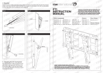
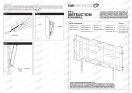
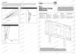
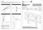
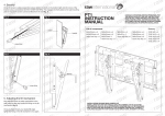
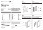
l
t
l
i
n
n
a
t
e
i
o
n
n
a
t
i
i
o
n
n
i
t
w
i
o
n
t
i
w
in atio
a
t
a
w
a
a
w
r
n
a
a
w
l
r
n
r
a
l
r
r
n
awinte
a
l
r
e
r
n
a
e
t
l
r
r
n
n
a
t
e
l
i
n
rawinternational
r
ra
raw
a
in
te
tern
rn
rnatio
ationa
atio
na
nal
l
n
a
t
e
i
o
n
n
a
t
i
i
o
n
n
i
t
w
i
n
t
io
w
in atio
a
t
a
w
a
a
w
r
n
a
a
w
l
r
n
r
a
l
r
r
n
VSA1
INSTALLATION
INSTRUCTIONS
a – LCD MOUNT
a
l
r
e
r
n
a
e
t
l
r
r
n
n
a
t
e
l
i
n
n
a
t
e
i
o
n
n
a
t
i
i
o
n
n
i
t
w
i
o
n
n
t
i
w
i
o
t
a
w
i
a
t
w
Step
2
–
Attaching
the Arm r
toa
the LCD rna
r
a
a
w
l
n
a
a
l
r
r
n
a
a
l
r
e
r
n
a
e
t
l
r
r
n
n
a
t
e
l
i
n
n
a
t
e
i
o
n
n
a
t
i
i
o
n
n
i
t
w
i
o
n
n
t
i
w
i
o
a
t
a
w
i
a
a
t
w
r
n
a
a
w rna
l
r
n
r
a
l
r
r
n
a
a
l
r
e
r
a
e
t
l
r
n
n
a
t
e
l
i
n
n
a
t
e
i
o
n
n
a
t
i
i
o
n
n
i
t
w
i
o
n
n
t
i
w
i
o
a
t
a
w
i
a
a
t
w
r
n
a
a
w rna
l
r
n
r
a
l
r
r
n
a
a
l
r
e
r
a
e
t
l
r
n
n
a
t
e
l
i
n
n
a
t
e
i
o
n
n
a
t
i
i
o
n
n
i
t
w
i
o
n
t
i
w
in atio
a
t
a
w
a
a
w
r
n
a
a
w
l
r
n
r
a
l
r
r
n
a
a
l
r
e
r
n
a
e
t
l
r
r
n
n
a
t
e
l
i
n
n
a
t
e
i
o
n
n
a
t
i
i
o
n
n
i
t
w
i
o
n Step 1w– Mounting
t
i
w
in the
o
a
t
a
w
i
Step
3 – Final Installation
anda
Operation
a
Wall
Piece w
t
r
n
a
a
l
r
n
r
a
a
l
r
r
n
a
a
l
r
e
r
n
a
e
t
l
r
r
n
n
a
t
e
l
i
n
n
a
t
e
i
o
n
n
a
t
i
i
o
n
n
i
t
w
i
o
n
n
t
i
w
i
o
a
t
a
w
i
a
a
t
w
r
n
a
a
w
l
r
n
r
a
a
l
r
r
n
a
a
l
r
e
r
n
a
e
t
l
r
r
n
n
a
t
e
l
i
n
n
a
t
e
i
o
n
n
a
t
i
i
o
n
n
i
t
w
i
o
n
n
t
i
w
i
o
a
t
a
w
i
a
a
t
w
r
n
a
a
w rna
l
r
n
r
a
l
r
r
n
a
a
l
r
e
r
a
e
t
l
r
n
n
a
t
e
l
i
n
n
a
t
e
i
o
n
n
a
t
i
i
o
n
n
i
t
w
i
o
n
n
t
i
w
i
o
a
t
a
w
i
a
a
t
w
r
n
a
a
w rna
l
r
n
r
a
l
r
r
n
a
a
l
r
e
r
a
e
t
l
r
n
n
a
t
e
l
i
n
n
a
t
e
i
o
n
n
a
t
i
i
o
n
n
i
t
w
i
o
n
t
i
w
in atio
a
t
a
w
a
a
w
r
n
a
a
w
l
r
n
r
a
l
r
r
n
a
a
l
r
e
r
n
a
e
t
l
r
r
n
n
a
t
e
l
i
n
n
a
t
e
i
o
n
n
a
t
i
i
o
n
n
i
t
w
i
n
t
io
w
in atio
a
t
a
w
a
a
w
r
n
a
a
w
l
r
n
r
a
l
r
r
n
a
a
l
r
e
r
n
a
e
t
l
r
r
n
n
a
t
e
l
i
n
n
a
t
e
i
o
n
n
a
t
i
i
o
n
n
i
t
w
i
n
t
io
w
in atio
a
t
a
w
a
a
w
r
n
a
a
w
l
r
n
r
a
l
r
r
n
a
l
r
e
r
n
a
e
t
l
r
n
a
t
e
l ra
in
n
n
a
t
e
i
o
n
n
Before beginning the installation of your new LCD mount, first verify that you have all
of the necessary tools at hand. The following tools are required for proper installation:
IMPORTANT: Make sure the LCD is unplugged before starting this
step of the installation and never lay the LCD face down as this may
damage the viewing surface.
• Phillips screwdriver
• Stud finder for drywall installation
• Electric drill and 5/16” (8mm) masonry bit for concrete/brick installation
Also make sure that all of the hardware has been included with your mount.
You should find the following:
x4 2.5” Drywall Screw (A)
x4 Concrete Anchor (B)
x4 M4x12mm Bolt
(C)
x4 M4x30mm Bolt
x4 3/4” Spacer
(D)
(E)
Drywall Installation
Drywall
IMPORTANT: The weight of the LCD requires installation into a wood
stud. Failure to do so may result in damage or injury.
Use a stud finder to locate a wood stud where you want to install your
mount. It is recommended that you verify the location of the stud using
mount.
a small nail or an awl. You should use the center of the stud.
After the stud has been located, place the wall piece against the wall
with the hook towards the bottom. Secure the wall piece using one
with
Drywall Screw (A), but do not completely tighten the screw. Using the
integrated bubble guide, carefully adjust the wall piece until it is level.
Insert the remaining screws into the wall piece and tighten.
Concrete/Brick Installation
Concrete/Brick
Begin by placing the wall piece into position against the wall with the
hook towards the bottom. Using the integrated bubble guide to keep it
level, mark off the holes that will be used for securing the mount and
place the wall piece aside. Next, drill holes using an electric drill and
place
5/16” (8mm) masonry bit. Remove any excess dust from the holes and
insert a Concrete Anchor (B) into each hole. If necessary, use a hammer
to lightly tap each anchor into place so that they are flush with the wall.
Once all of the anchors are in place, put the wall piece back into
Once
position. Attach the wall piece using the Drywall Screws (A) provided.
Make sure all screws are snug, but be careful not to over-tighten them.
x1 Security Bolt
x1 Allen Wrench
(F)
(G)
Before attaching the arm piece of the mount to your LCD, you must first
determine which hardware to use. Do this by examining the back of the
LCD. If your LCD has a flat back, use the M4x12mm Bolts (C). If your
LCD has a recessed back, use the longer M4x30mm Bolts (D) and 3/4”
Spacers (E). After you have determined the appropriate bolts, use them
to attach the arm piece of the mount to the back of your LCD. Be careful
not to over-tighten the bolts.
Final Installation
To complete the installation, simply slide the arm piece with your LCD
attached into the wall piece. The plastic tab on the top of the wall
piece should click indicating that the arm piece is secure. If you need
to remove the arm piece, push in on the tab and slide the arm up. For
additional security and stability, insert the security bolt (F) into the hole
located on base of the arm piece and tighten using the Allen Wrench (G)
included in the hardware kit.
Operation and Adjustment
NOTE: Adjustment of your LCD may vary by model.
On most models, the tilt angle of your LCD can be adjusted by first
loosening the gear joint that holds the tilt in place. To do this, locate the
adjustment knob directly behind the LCD mounting point. Loosen it by
turning the knob counter-clockwise. Adjust the tilt to the desired level
and re-tighten the knob (see illustration).
-20º/+
//+20
+20
20º
Other viewing adjustments can be made by simple moving the arm into
the desired position. If you find that a joint is too difficult to move or does
not hold the LCD in place, you can adjust the tightness of the joint. If
your mount includes black adjustment knobs, turn a knob clockwise to
tighten and counter-clockwise to loosen. If your mount does not have
knobs, use the Allen Wrench (G) to tighten or loosen the joint.