Transcript
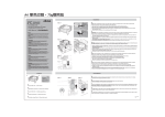
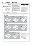
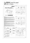
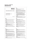
297 mm x 420mm 單色印刷
akasa
Installation
STEP 3
STEP 1
InterConnect
D
drive bay data panel
5 port USB2.0 hub / IEEE1394 & eSATA ports
PSU 4-pin
molex
connector
GB
Connect the internal USB, IEEE1394, SATA connectors to the
corresponding motherboard headers. Connect the power 4-pin
molex connector to the PSU peripheral connector.
NOTE: If the connectors are not apparent on the board consult your
motherboard manual. Connecting the panel to the wrong headers may
result in motherboard damage.
User manual
FR
GB
AKASA Company notices
The information contained in this document is subject to
change without notice.
All rights reserved. Reproduction, adaptation, or translation of
this material is prohibited without prior written permission of
AKASA, except as allowed under copyright laws. The only
warranties for AKASA products and services are set forth in
the express warranty statements accompanying such products
and services. Nothing herein should be construed as
constituting an additional warranty. AKASA shall not be liable
for technical or editorial errors or omissions contained herein.
Secure the card reader with the screws provided or the
case 3.5" mounting system.
GB
Remove the cover of an empty 3.5’’ external drive bay. Switch
off the system power and open the case side panel.
FR
Retirez le couvercle d’une baie de lecteur externe 3,5 pouces vide.
Eteignez l’alimentation du système et ouvrez le panneau latéral du
boîtier.
D
Entfernen Sie die Abdeckung eines freien, externen 3.5"
Laufwerkschachtes. Schalten Sie das System aus und öffnen Sie das
Seitenabdeckung des Gehäuses.
ES
Quite la tapa de una bahía de unidad externa vacía de 3,5". Apague
la alimentación del sistema y abra el panel lateral de la carcasa.
PT
Remova a tampa de uma baia externa de 3.5” vazia. Desligue o
sistema e abra o painel lateral do gabinete.
Pre - installation
FR
Fixez le lecteur de carte avec les vis fournies ou avec le système de
montage 3,5 pouces du boîtier.
D
Sichern Sie den Kartenleser mit Hilfe der im Lieferumfang
enthaltenen Schrauben oder dem 3.5" Befestigungssystem des
Gehäuses.
ES
Fije el lector de tarjetas con los tornillos suministrados o con el
sistema de montaje de 3,5".
PT
Fixe o leitor com os parafusos que acompanham ou utilize o sistema
de fixação 3.5" do gabinete.
STEP 4
D
Verbinden Sie den internen USB, IEEE1384 und den SATA Anschluss mit
dem entsprechenden Motherboard-Anschluss. Verbinden Sie nun den
4-Pin Molex (Strom) mit einem entsprechenden Netzteilstecker.
HINWEIS: Sollten die entsprechenden Motherboard-Anschlüsse nicht
auffindbar sein, so schauen Sie bitte in der Dokumentation ihres
Motherboards nach. Ein anschließen an die falschen Anschlüsse könnte
eine Beschädigung des Motherboards zur Folge haben.
ES
Enchufe los conectores internos USB, IEEE1394 y SATA a sus
correspondientes cabezales en la placa madre. Conecte el conector Molex
de electricidad de 4 pines a la conexión para periféricos de la fuente de
alimentación.
NOTA: Si los conectores no aparecen identificados en su placa madre,
consulte el manual de la misma. Conectar el panel a los cabezales
equivocados puede causar un daño permanente de la placa.
PT
Conecte os conectores internos USB, IEEE1394, SATA nas entradas
correspondentes da placa-mãe. Conecte o conector de força 4-pin
molex na fonte de alimentação.
NOTA: Caso você não encontre as entradas na placa-mãe, consulte o
manual da placa-mãe. Conectar o painel na entrada errada, pode causar
danos à placa-mãe.
STEP 2
GB
WARNING
Electrostatic discharge (ESD) can damage system components.
Use an ESD controlled workstation. If such a workstation is not
available, wear an antistatic wrist strap or touch an earthed
surface before handling any PC components.
Connectez les connecteurs internes USB, IEEE1394, SATA aux interfaces
correspondantes de la carte mère. Connectez le connecteur d’alimentation
molex à 4 broches au connecteur périphérique PSU.
REMARQUE: Si vous ne trouvez pas les connecteurs, consultez le manuel
de votre carte mère. Si vous connectez le boîtier aux mauvaises interfaces,
votre carte mère sera endommagée.
Operation
IEEE1394
10-pin header
A
FR
ATTENTION
Une décharge électrostatique (ESD) peut endommager les composants
du système. Utilisez une station de travail protégée contre l’ESD. Si
vous ne disposez pas d’une telle station de travail, portez un bracelet
antistatique ou touchez une surface connectée à la masse avant de
manipuler les composants du PC.
D
WARNUNG
Die Systemkomponenten können durch elektrostatische Entladung
beschädigt werden. Benutzen Sie einen for ESD schützenden
Arbeitsplatz. Sollte ein solcher Arbeitspaltz nicht verfügbar sein,
tragen Sie ein antistatisches Armband or berühren Sie eine geerdete
Oberfläche vor dem hantieren mit PC Komponenten.
ES
ADVERTENCIA
La descarga electrostática (ESD) puede dañar componentes en el
sistema. Use una estación de trabajo controlada ESD. Si no tiene
disponible dicho lugar de trabajo, colóquese una muñequera
antiestática o toque la superficie conectada a tierra antes de tocar
componentes en el PC.
PT
Cuidado
A descarga eletrostática (ESD) pode danificar os componentes do
sistema.
Se uma bancada técnica não estiver disponível, use uma pulseira antiestática ou toque em uma superfície aterrada antes de manusear
qualquer componente.
GB
GB
Insert the Inter Connect panel into the drive bay until it is in
line with front panel of the chassis.
USB 10-pin
header
B
FR
Insérez le boîtier Inter Connect dans la baie du lecteur en l’alignant
avec le panneau avant du châssis.
Fermez le châssis et démarrez le système. Windows reconnaîtra la puce du
hub USB et installera les pilotes automatiquement. REMARQUE: Les quatre
ports USB marqués sont bufferisés par la puce. Le cinquième port passe par
la carte mère.
Bauen Sie das Gehäuse wieder zusammen und starten Sie den PC. Windows
wird den USB HUB Chipset automatisch erkennen und die dazugehörigen
Treiberprogramme selbstständig installieren.
HINWEIS: Die vier gekennzeichneten USB-Anschlüsse sind vom Chipset
gepuffert. Der fünfte USB-Anschluss ist vom Motherboard durchgereicht.
Schieben Sie das Inter Connect panel in den Laufwerkschacht bis es
bündig mit der Vorderseite des Computergehäuses abschließt.
ES
Inserte el panel Inter Connect dentro de la bahía hasta que esté
alineado con el panel frontal de la caja del ordenador.
Insira o leitor Inter Connect na baia até que ele fique alinhado com
a frontal do gabinete.
FR
D
D
PT
Close the chassis and boot up the system. Windows will recognize the USB
hub chipset and install the drivers automatically. NOTE: The four marked
USB ports are buffered by chipset. The fifth port is pass through from
motherboard.
ES
C
SATA
connector
Cierra la caja y reinicie el sistema. Windows reconocerá el chipset del hub
USB e instalara los drivers necesarios automáticamente. NOTA: Los cuatro
puertos USB señalados son manejados por el chipset. El quinto puerto se
comunica directamente con la placa madre.
PT
Feche o gabinete e ligue o sistema. O windows vai reconhecer o chipset do
hub USB e instalar os drivers automaticamente. NOTA: As quatro portas
USB assinaladas são controladas por chipset. A quinta porta é controlada
pela placa-mãe.
2008/12/02
AK-ICR-08