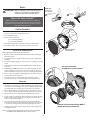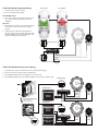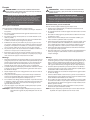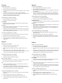
1
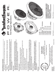
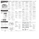
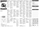
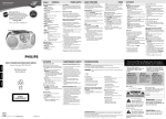
05/2009 B.M.
05/2009 E.R.
1230-55855-01
2009 Rockford Corporation. All rights reserved.
Rockford Fosgate and the Rockford Fosgate logo are either
registered trademarks or trademarks of Rockford Corporation.
Printed in China
Designed and Engineered by Rockford Fosgate,Tempe, AZ. USA.
www.rockfordfosgate.com
Rockford Corporation
600 South Rockford Drive
Tempe, Arizona 85281 U.S.A.
In U.S.A., (480) 967-3565 - Customer Service 1-800-669-9899
Rockford Fosgate
This product meets the current EU warranty requirements, see your Authorized dealer for details.
EU Warranty
Contact the Authorized Rockford Fosgate Dealer you purchased this product from. If you need further
assistance, call 1-800-669-9899 for Rockford Customer Service.You must obtain an RA# (Return
Authorization number) to return any product to Rockford Fosgate.You are responsible for shipment
of product to Rockford.
How to Obtain Service
Any implied warranties including warranties of fitness for use and merchantability are limited in duration to the
period of the express warranty set forth above. Some states do not allow limitations on the length of an implied
warranty, so this limitation may not apply. No person is authorized to assume for Rockford Fosgate any other
liability in connection with the sale of the product.
Limit on Implied Warranties
1. Damage caused by accident, abuse, improper operations, water, theft, shipping
2.Any cost or expense related to the removal or reinstallation of product
3. Service performed by anyone other than Rockford or an Authorized Rockford Fosgate Service Center
4.Any product which has had the serial number defaced, altered, or removed
5. Subsequent damage to other components
6.Any product purchased outside the U.S.
7.Any product not purchased from an Authorized Rockford Fosgate Dealer
What is Not Covered
This warranty covers only the original purchaser of Rockford product purchased from an Authorized
Rockford Fosgate Dealer in the United States. In order to receive service, the purchaser must provide
Rockford with a copy of the receipt stating the customer name, dealer name, product purchased and date of
purchase. Products found to be defective during the warranty period will be repaired or replaced
(with a product deemed to be equivalent) at Rockford's discretion.
Who is Covered
This warranty applies only to Rockford Fosgate products sold to consumers by Authorized Rockford Fosgate
Dealers in the United States of America or its possessions. Product purchased by consumers from an
Authorized Rockford Fosgate Dealer in another country are covered only by that country’s Distributor and
not by Rockford Corporation.
What is Covered
Speakers – 1 Year. Any Factory Refurbished Product – 90 days (receipt required)
Length of Warranty
Rockford Corporation offers a limited warranty on Rockford Fosgate products on the following terms:
LIMITED WARRANTY STATEMENT
Serial Number:
Date of Purchase:
Installation et fonctionnement
Instalación y funcionamiento
Einbau und Betrieb
Installazione e funzionamento
Installation & Operation
T1T-S – Tweeter System
T152-S – 5.25˝
T1652-S – 6.5˝
Component Systems
SAFETY
T152S Only
CAUTION: Before installation, disconnect the battery
negative (-) terminal to prevent damage
to the unit, fire and/or possible injury.
Removing tabs for
some installations
Use pliers to break off
plastic tab.
Break off
mounting tab.
PRACTICE SAFE SOUND™
snap!
Continuous exposure to sound pressure levels over 100dB may
cause permanent hearing loss. High powered auto sound systems
may produce sound pressure levels well over 130dB. Use common
sense and practice safe sound.
Position to
Align Holes
CARTON CONTENTS
• (1) Set T1 Series Speakers with Tweeters and 2-Way Crossover
or (1) Set T1 Series Tweeters with HP Crossover
Cutout
Hole
• (1) Set of grilles/trim rings
• (2) Sets of tweeter trim rings:
(1 set of polished aluminum)
(1 set of brushed aluminum)
• Tweeter Mounting Hardware with Surface, Angle, and Flush Mounts
• (1) Set Adapter Plates: T152-S (5”x7”/6”x9”), T162-S (5”x7”/6”x9”)
Example of standard
door installation
INSTALLATION CONSIDERATIONS
Before beginning any installation, follow these simple rules:
1.
2.
3.
4.
5.
6.
7.
1.
2.
3.
4.
5.
6.
Be sure to carefully read and understand the instructions before attempting to
install these speakers.
For safety, disconnect the negative lead from the battery prior to beginning the
installation.
For easier assembly, we suggest you run all wires prior to mounting your speakers
in place.
Use high quality connectors for a reliable installation and to minimize signal or
power loss.
Use tip of a small flat
screwdriver to remove tweeter
Think before you drill! Be careful not to cut or drill into gas tanks, fuel lines,
brake or hydraulic lines, vacuum lines or electrical wiring when working on any
vehicle. If installation in a boat, take care not to cut or drill through the main hull.
Never run wires underneath the vehicle. Running the wires inside the vehicle or
hull area provides the best protection.
Avoid running wires over or through sharp edges. Use rubber or plastic
grommets to protect any wires routed through metal, especially the firewall.
MOUNTING
Determine where the speakers will be mounted. Ensure an area large enough for
the speaker to mount evenly. Be sure that the mounting location is deep enough
for the speaker to fit; if mounting in a door, operate all functions (windows, locks,
etc.) through their entire operating range to ensure there is no obstruction.
Refer to the specification chart to determine the proper diameter hole to cut
for your speaker model.The template provided also gives the proper cutout size.
Mark the locations for the mounting screws. Drill the holes with a 1/8" bit.
Panel
Feed the speaker wires through the cutout and connect to the speaker terminals.
Be sure to observe proper polarity when connecting the wires.The speaker's
positive terminal is indicated with a "+".
On models with slotted holes, fit the speaker into the cutout and install the
screws in the slots at the top and bottom.This will allow you to rotate the speaker to match the remaining mounting holes.When aligned, tighten the screws.
Example of Discreet Dual Clamp (DDC™)
Tweeter Mounting (Flush Mount)
Tighten the screws until the speaker is snug in place to prevent rattling. Do not
over tighten the screws.
NOTE: If needed, use the adapter plate provided to mount the speaker.
See Adapter Plate Templates at the end of this manual.
2
SPECIFICATIONS
FEATURES
WIRING
T1T-S Crossover Wiring
1.
Use illustration for proper connection.
3.
Connecting the positive wire to 0dB matches the
amplitude of the tweeter to the mid-range (woofer).
2.
4.
Be sure to maintain speaker polarity.
Connecting positive wire to -2dB or -4dB to reduce
the amplitude of the tweeter -2dB or -4dB lower
than the mid-range, (ideal for tweeters located high
in door panels and mid-range low in the kick panel).
T1T-S
Nominal Diameter - inch (mm)
5.25 (133)
6.5 (165)
1.0 (25.4)
Description
Component System Component System
Tweeter System
Nominal Impedance (ohms)
4Ω
4Ω
4Ω
Frequency Response (Hz)
65Hz - 20kHz
55Hz - 22kHz
3kHz - 22kHz
Crossover Frequency (Hz)
3.5kHz
3kHz
3kHz
High-Pass Butterworth Crossover
18dB/octave
18dB/octave
18dB/octave
Low Pass Butterworth Crossover
12dB/octave
12dB/octave
–
Voice Coil Diameter - inch (mm)
1.1 (28)
1.2 (31)
1.0 (25.4)
Fs - Free Air Resonance (Hz)
65
55
1.8kHz
Qts
0.60
0.50
–
Vas - cu. ft. (Liter)
0.34 (9.6)
0.56 (16)
–
Xmax - inch (mm)
0.16 (4.0)
0.24 (6.0)
–
SPL (dB @ 1w/1m)
87 dB
89 dB
90 dB
Power Handling-Watts (RMS / Peak)
75 / 150
100 / 200
75 / 150
Rec. Amp Power-Watts (RMS)
22.5W ~ 75W
30W ~ 100W
22.5W ~ 75W
Mounting Diameter-inch (mm)
4.80 (122)
5.59 (142)
1.75 (45) (Flush Mount)
Mounting Depth-inch (mm)
2.03 (52)
2.51 (64)
0.95 (24) (Flush Mount)
Includes Grille/Trim Ring
YES
YES
YES
Trim Ring Diameter-inch (mm)
6.22 (158)
6.949 (177)
2.13 (54)
Trim Ring Height-inch (mm)
1.06 (27)
1.18 (30)
0.31 (8)
Includes Adapter Plate
5"x7"/6"x9"
5"x7"/6"x9"
NO
See figures on following pages.
Tweeter On-Axis
Specifications subject to change without notice.
Tweeter Off-Axis
OUTPUT
AXIS ON
OUTPUT
AXIS ON
OFF
OFF
Do Not Use
Do Not Use
Tweeter
(TWT)
Tweeter (+)
Tweeter (+)
Connect Only
ONE (+) Terminal
0dB
INPUT
-2dB 0dB
-2dB
-4dB
-4dB
NEG
The “mounting cups” are in fact not “cups” at all,
but rather unobtrusive “clamps” that quickly
and easily mount in a standard 1.75 inch (45mm)
hole saw opening with a single center screw
securing with balanced pressure to both faces
of the mounting surface. From there, the tweeter
simply snaps into place and is secured by a
snap-on trim ring. Removal is easy if needed.
The protective grille on the tweeter is
non-removable and an intergral part of the design.
T1652-S
OUTPUT
AXIS ON
Every aspect of the new Tweeter design has been
completely re-engineered to allow for maximum
ease of installation and fitment.This optimized
patent pending design provides concentric
clamping pressure around the perimeter of the
mounting hole.
T152-S
T1 Components
NEG
OFF
Discreet Dual Clamp (DDC™)
Tweeter Mount
ON
OFF
Connect Only
ONE (+) Terminal
3
T152-S & T1652-S Component Wiring
1.
2.
Tweeter On-Axis
Use illustration for proper connection.
Tweeter Off-Axis
Be sure to maintain speaker polarity.
Axis ON-OFF Switch
1.
Set to ON or OFF to match position of tweeter relative to listener. Default OFF position satisfies most
installations.
dB Switch
1.
2.
0dB matches the amplitude (no increase/no attenuation)
of the tweeter to the same level as the mid-range
(woofer).
+2dB increases and -2dB reduces the amplitude of
tweeter in relation to the mid-range, (ideal when matching offset installation like tweeters located high in door
panels and midranges low in kick panels).
ON
ON
AXIS
AXIS
Tweeter Axis Switch
OFF
OFF
INPUT
0dB
+ TWT -
+ WFR -
Woofer
(WFR)
Tweeter
(TWT)
OUTPUT
+ TWT -
+ WFR -
ON
-2dB
AXIS
-4dB
OFF
+2dB
0dB
+2dB
-2dB
0dB
Tweeter Attenuation Switch
-2dB
T152-S & T1652-S Bi-Amp Cossover Wiring
1.
2.
3.
4.
Use illustration for proper connection and be sure to maintain speaker polarity.
Remove 4 screws from crossover bottom to detatch cover.
When BI-AMP switched OFF for one amplifier, use only “TWT” input.
When BI-AMP switched ON for two dedicated amplifier, use both “TWT” and “WFR” inputs.
Default Setting
OFF
BI-AMP
ON
Standard Mode
INPUT
+ TWT -
+2dB
Full-Range
Amplifier
Crossover Cover Removal
Remove 4 Screws From
Bottom to Detatch Cover
-2dB -4dB
OFF
+ TWT -
BI-AMP
ON
+ WFR -
OFF-DEFAULT
+ TWT -
OFF AXIS
DEFAULT
OUTPUT
+ TWT -
+ WFR -
ON
AXIS
OFF
Woofer
(WFR)
Tweeter
(TWT)
Woofer
(WFR)
Tweeter
(TWT)
Use TWT In
WFR Not Used
Bi-Amp Mode
OFF
0dB
+ WFR -
0dB
-2dB
BI-AMP
ON
Dedicated
Tweeter
Amplifier
ON
+ WFR -
INPUT
+2dB
OFF
+ TWT -
BI-AMP
ON
+ WFR -
+ TWT -
Dedicated
Mid-Range (woofer)
Amplifier
4
+ TWT -
+ WFR -
OUTPUT
+ TWT -
+ WFR -
ON
0dB
AXIS
-2dB
OFF
SPECIFICATIONS
T152-S
6.02"
T152-S
(153mm)
T1652-S
T1652-S
6.02"
3.84" (153mm)
(98mm) 3.84"
(98mm)
6.77"
(172mm) 6.77"
4.37" (172mm)
(111mm) 4.37"
(111mm)
6.22"
(158mm) 6.22"
(158mm)
6.97"
(177mm) 6.97"
(177mm)
1.06"
(27mm) 1.06"
(27mm)
2.45"
(62mm) 2.45"
2.03"
(62mm)
(52mm) 2.03"
(52mm)
5.59"
(142mm) 5.59"
(142mm)
2.10"
(53mm)
T152-S & T1652-S
T152-S Crossover
& T1652-S
Component
Component Crossover
0.30"
(8mm)
0.50"
(13mm)
4.57"
(116mm) 4.57"
(116mm)
4.09"
(104mm) 4.09"
(104mm)
0.50"
(13mm)
1.38"
(35mm)
Surface Mount
Surface
Mount
1.06"
(27mm)
1.06"
(27mm)
3.35"
(85mm) 3.35"
2.85" (85mm)
(73mm) 2.85"
(73mm)
5
NEG
1.59"
1.9"
(41mm) (48mm)
1.59"
1.9"
(41mm) (48mm)
OFF
1.18"
(30mm)
0.97"
(25mm)
1.26"
(32mm)
Specifications subject to change without notice.
OUTPUT
AXIS ON
NEG
0.97"
(25mm)
OFF
0.91"
(23mm)
INPUT
-2dB 0dB
0.91"
(23mm)
NEG
1.75"
0.32" (44mm) 1.75"
(9mm)
(44mm)
-4dB
(9mm)
INPUT
-2dB 0dB
2.13"
(54mm)
-4dB
2.13"
(54mm)
Hole
Mounting
Flush Mount Mounting
Diameter
Depth Mounting
Mounting Hole
Flush
Mount
Diameter
Depth
0.32"
T1T-S
T1T-S
Tweeter
Crossover
Tweeter Crossover
NEG
2.13"
(54mm)
1.38"
(35mm)
OUTPUT
AXIS ON
2.13"
(54mm)
4.57"
(116mm) 4.57"
(116mm)
4.09"
(104mm) 4.09"
(104mm)
Tweeter
Tweeter
0.30"
(8mm)
1.18"
(30mm) 1.18"
(30mm)
2.94"
(75mm) 2.94"
(75mm)
2.51"
(64mm) 2.51"
(64mm)
4.80"
(122mm) 4.80"
(122mm)
2.10"
(53mm)
6.18"
(157mm) 6.18"
Diameter
(157mm)
Diameter
5.43"
(138mm) 5.43"
Diameter
(138mm)
Diameter
1.26"
(32mm)
3.16"
(80mm)
3.16"
(80mm)
1.38"
(35mm)
1.38"
(35mm)
1.18"
(30mm)
Français
Español
MISE EN GARDE : avant d'entamer l'installation, déconnectez la
broche négative (-) de la batterie pour éviter tout risque de blessures,
d’incendie ou de dommages à l'appareil.
PRECAUCIÓN: Antes de la instalación, desconecte el terminal
negativo de la batería (-) para prevenir daño a la unidad, incendio y/o
posibles lesiones.
PRACTIQUE EL SONIDO SEGURO
El contacto continuo con niveles de presión de sonido superiores a 100 dB
puede causar la pérdida permanente de la audición. Los sistemas de sonido para
automóviles de alta potencia pueden producir niveles de presión de sonido
superiores a los 130 dB. Use su sentido común y practique el sonido seguro.
PRATIQUEZ UNE ÉCOUTE SANS RISQUESMD
Une exposition continue à des niveaux de pression acoustique supérieurs
à 100 dB peut causer une perte d'acuité auditive permanente. Les
systèmes audio de forte puissance pour auto peuvent produire des
niveaux de pression acoustique bien au-delà de 130 dB. Faites preuve de
bon sens et pratiquez une écoute sans risques
Consideraciones para la instalación
Notes pour l'installation
Antes de comenzar cualquier instalación, siga estas simples normas:
1. Asegúrese de leer cuidadosamente y de entender las instrucciones antes de
tratar de instalar estos altavoces.
2. Por seguridad, desconecte el conductor negativo de la batería antes de comenzar
la instalación.
3. Para facilitar el montaje, sugerimos que tienda todos los cables antes de montar
sus altavoces en su sitio.
4. Utilice conectores de alta calidad para tener una instalación confiable y para
reducir al mínimo las pérdidas de señal o de potencia.
5. ¡Piense siempre antes de perforar! Tenga cuidado de no cortar ni perforar en tanques de combustible, tuberías de combustible, frenos o hidráulicas, tuberías de
vacío o cableado eléctrico al trabajar en un vehículo. Si la instalación se hace en
un bote, tenga cuidado de no cortar ni perforar a través del casco principal.
6. Nunca tienda cables abajo del vehículo.Tender los cables adentro del vehículo o
casco proporciona la mejor protección.
7. Evite tender cables arriba o a través de bordes filosos. Use arandelas aislantes de
caucho para proteger los cables tendidos a través de metal, especialmente la
mampara cortafuegos.
Montage
Montaje
2.
2.
Avant de commencer l'installation, suivez les règles ci-dessous :
1. Veillez à bien lire et comprendre les instructions avant d'essayer d'installer les
haut-parleurs.
2. Par mesure de sécurité, débranchez le fil négatif de la batterie avant de commencer l'installation.
3. Pour faciliter le montage des haut-parleurs, il est conseillé d'installer tous les
câbles au préalable.
4. Utilisez des connecteurs de haute qualité pour assurer une installation fiable
et réduire au minimum la perte de signal ou de puissance.
5. Réfléchissez bien avant de percer.Veillez à ne pas couper ou percer le réservoir d'essence, le câblage électrique ou les conduites de carburant, de freinage
hydraulique ou de dépression en travaillant sur un véhicule. En cas d'installation sur un bateau, veillez à ne pas couper ou percer la coque principale.
6. Ne jamais faire passer de fils sous le véhicule. Leur installation à l'intérieur du
véhicule ou de la coque assure la meilleure protection.
7. Évitez de faire passer des fils sur des bords tranchants ou dans des orifices à
arêtes vives. Utilisez des bagues en caoutchouc ou en plastique pour protéger
les fils traversant une plaque de métal, notamment le tablier.
1.
3.
4.
5.
6.
1.
Déterminez l'emplacement des haut-parleurs.Veillez à ce que la surface plane soit
assez grande pour assurer un contact uniforme du haut-parleur.Vérifiez que l'emplacement est assez profond pour le haut-parleur ; en cas de montage dans une
portière, actionnez toutes les commandes (fenêtres, serrures, etc.) jusqu'aux
extrémités de leurs courses pour vous assurer qu'il n'y a pas d'obstruction.
Consultez le tableau des caractéristiques pour déterminer le diamètre de l'orifice
à découper pour votre modèle de haut-parleur. Le gabarit fourni donne aussi le
bon diamètre de découpe.
Marquez l'emplacement des vis de montage. Percez les trous avec une mèche de
1/8 de pouce (3,2 mm).
Faites passer les fils de haut-parleur à travers l'orifice découpé et branchez-les
aux bornes du haut-parleur.Veillez à bien respecter la polarité lors du branchement. La borne positive du haut-parleur est indiquée par un « + ».
3.
4.
5.
Sur les modèles à trous allongés, mettez le haut-parleur en place dans la découpe
et installez les vis dans les trous du haut et du bas.Vous pourrez alors faire tourner le haut-parleur pour l'aligner sur les autres trous de montage. Une fois cet
alignement effectué, serrez les vis.
6.
Serrez les vis jusqu'à ce que le haut-parleur soit bien ajusté, de façon à prévenir
tout cliquetis, mais évitez tout serrage excessif.
Determine adónde se montará los altavoces.Asegúrese de que haya un área suficientemente grande para montar de manera plana el altavoz.Asegúrese de que el
lugar de montaje sea suficientemente profundo para que quepa el altavoz, si se
monta en una puerta, accione todas las funciones (ventanas, cerradura, etc.) en
toda su gama de funcionamiento para asegurarse de que no haya obstrucciones.
Consulte la tabla de especificaciones para determinar cuales son los diámetros
correctos para el agujero a cortar para su modelo de altavoz. La plantilla proporcionada también le da la medida correcta del recorte.
Marque las localidades para los tornillos de montaje. Perfore los agujeros usando
una broca de 1/8 pulg.
Tienda los cables del altavoz a través del recorte y conecte a los terminales del
altavoz.Asegúrese de usar la polaridad correcta al conectar los cables. El terminal
positivo del altavoz está identificado con un símbolo "+".
En los modelos con agujeros ranurados, coloque el altavoz en el recorte e instale
los tornillos en las ranuras en la parte superior e inferior. Esto le permitirá hacer
girar el altavoz para que coincida con los agujeros de montaje restantes. Una vez
alineados, apriete los tornillos.
Apriete los tornillos hasta que el altavoz esté ajustado en su sitio para evitar
vibraciones. No apriete demasiado los tornillos.
NOTA:Use la placa adaptadora proporcionada para montar el altavoz. Consulte
las plantillas de las placas adaptadoras al final de este manual.
REMARQUE: Utilisez si nécessaire la plaque d'adaptation fournie pour monter le
haut-parleur.Voir les gabarits de plaque d'adaptation à la fin de cette
notice.
6
Deutsch
Italiano
ATTENZIONE: Prima dell'installazione, scollegate il terminale
negativo (-) della batteria per evitare danni all'unità, pericoli d'incendio
e/o potenziali lesioni personali.
VORSICHT: Entfernen Sie vor dem Einbau den negative Batteriepol,
um Schäden am Gerät, Feuer bzw. mögliche Verletzungen zu vermeiden.
PRAKTIZIEREN SIE SICHEREN SOUND
Fortgesetzte Geräuschdruckpegel von über 100 dB können beim Menschen zu
permanentem Hörverlust führen. Leistungsstarke Autosoundsysteme können
Geräuschdruckpegel erzeugen, die weit über 130 dB liegen. Bitte wenden Sie
gesunden Menschenverstand an und praktizieren Sie sicheren Sound.
OSSERVATE LE REGOLE DEL “SUONO SENZA PERICOLI”
La costante esposizione a livelli di pressione acustica al di sopra dei 100dB
possono causare la perdita permanente dell’udito. I sistemi audio ad alta potenza
possono produrre livelli di pressione acustica ben superiori ai 130dB. Si consiglia
il buon senso e l’osservanza delle regole del “suono senza pericoli”
Considerazioni sull'installazione
Einbauüberlegungen
Prima di iniziare qualsiasi operazione d'installazione, vi consigliamo di seguire
queste semplici regole:
1. Assicuratevi di aver letto tutte le istruzioni con cura e di averle capite prima di effettuare qualsiasi tentativo d'installazione neiconfronti dell'unità.
2. Per motivi di sicurezza, scollegate il cavo negativo dalla batteria prima di dare l'avvìo
all'installazione.
3. Per facilitare il montaggio, vi suggeriamo di far scorrere tutti i fili prima di montare la
vostra unità nella sua ubicazione.
4. Usate connettori di alta qualità per garantire un'installazione che dà affidamento e per
ridurre al minimo la perdita di segnali o di potenza.
5. State attenti prima di trapanare! Cercate di non trapanare e di non incidere i serbatoi
della benzina; le condutture del carburante, dei freni, del sistema idraulico e a depressione; nonché i fili elettrici quando state lavorando su qualsiasi veicolo.
6. Non fate mai scorrere i fili sotto il veicolo.Avrete la protezione migliore faccendo
scorrere i fili all'interno del veicolo.
7. Evitate di far scorrere i fili sopra o attraverso delle estremità affilate. Usate guarnizioni
di tenuta in gomma o in plastica per proteggere qualsiasi filo che passi attraverso del
metallo, soprattutto il parafiamma.
Befolgen Sie vor dem Einbau diese einfachen Regeln:
1. Lesen Sie die Anleitung sorgfältig, bevor Sie versuchen diese Lautsprecher einzubauen.
2. Entfernen Sie vor dem Einbau aus Sicherheitsgründen das negative Kabel von der
Batterie.
3. Um die Montage zu erleichtern, empfehlen wir alle Kabel vor der Befestigung Ihrer
Lautsprecher zu verlegen.
4. Verwenden Sie nur Qualitätsstecker, um einen zuverlässigen Einbau zu gewährleisten
und Signal- und Stromverlust zu minimieren.
5. Denken Sie nach, bevor Sie bohren! Achten Sie darauf, nicht in den Benzintank, die
Benzin-, Brems- oder hydraulischen Leitungen,Vakuumleitungen oder Elektrokabel zu
schneiden oder zu bohren, wenn Sie am Fahrzeug arbeiten.Achten Sie beim Einbau in
einem Boot darauf, nicht durch den Bootsrumpf zu schneiden oder zu bohren.
6. Verlegen Sie Kabel nie unter dem Fahrzeug. Die Kabel im Fahrzeug oder Bootsrumpf
zu verlegen, bietet den besten Schutz.
7. Vermeiden Sie es, Kabel über scharfe Kanten zu verlegen.Verwenden Sie Gummi- oder
Plastikringe, um Kabel zu schützen, die durch Metall verlegt werden (besonders die
Feuerwand).
Befestigung
1.
2.
3.
4.
5.
6.
Entscheiden, wo die Lautsprecher befestigt werden sollen. Gewährleisten, dass der
Platz ausreicht, um den Lautsprecher gleichmäßig zu befestigen. Gewährleisten, dass
die Befestigungsstelle ausreichende Tiefe für den Lautsprecher hat; beim Einbau in
einer Türe alle Funktionen (Fenster, Schloss usw.) in ihrem ganzen Bereich ausprobieren um zu gewährleisten, dass keine Blockierung eintritt.
Die Tabelle in den Technischen Daten gibt den richtigen Lochdurchmesser für Ihr
Lautsprechermodell zum Ausschneiden an. Die beiliegende Schablone zeigt ebenfalls
die richtige Ausschneidegröße an.
Die Stellen für die Befestigungsschrauben markieren. Die Löcher mit einer 1/8-Zoll
(3,2 mm) Bohrerspitze bohren.
Die Lautsprecherkabel durch das Loch führen und an den Lautsprecherausgängen
anschließen. Beim Anschließen der Kabel die ordnungsgemäße Polarität beachten.
Der positive Anschluss des Lautsprechers ist mit einem „+“ markiert.
Bei Modellen mit geschlitzten Löchern den Lautsprecher in das Loch einpassen und
die Schrauben in den Schlitzen oben und unten befestigen. Dadurch können Sie den
Lautsprecher so drehen, dass die übrigen Befestigungslöcher passen. Nach der
Ausrichtung die Schrauben anziehen.
Die Schrauben anziehen, bis der Lautsprecher eng an seinem Platz anliegt, um
Klappern zu verhindern. Die Schrauben nicht zu fest anziehen.
HINWEIS:
Montaggio
1. Decidete dove montare gli altoparlanti.Assicuratevi che sia un'area abbastanza
grande per poter montare l'altoparlante a livello e abbastanza profonda per poterlo
collocare comodamente. Se lo montate all'interno di uno sportello, controllate tutte
le funzioni (finestre, serrature, ecc.), una alla volta, per assicurarvi che non ci siano
ostruzioni.
2. Fate riferimento alla tabella delle specifiche per stabilire il diametro corretto del foro
che dovrete praticare per il modello del vostro altoparlante. Il modello fornito anche
dà la dimensione adeguata del ritaglio.
3. Marcare le posizioni per le viti di montaggio. Praticare i fori con una punta da trapano di 1/8 di pollice (3,2 mm).
4. Passare i cavi del diffusore tramite l'apertura e collegarli ai terminali.Verificare che la
polarità sia corretta quando si collegano i cavi. Il terminale positivo del diffusore è
identificato dal "+".
5. Nei modelli con fori a slot, adattare il diffusore nel foro ritagliato e inserire le viti
negli slot in alto e in basso. Così facendo si potrà ruotare il diffusore per allinearlo
con i rimanenti fori di montaggio. Serrare le viti quando si è ottenuto l'allineamento.
6. Per evitare rumore dovuto a vibrazioni serrare le viti finché il diffusore non sia saldamente in posizione. Non serrare le viti in modo eccessivo.
Falls erforderlich die beiliegende Adapterplatte bei der Befestigung des
Lautsprechers verwenden. Siehe Adapterplatten-Schablonen am Ende
dieser Anleitung.
NOTA: Se necessario, della piastra di adattamento in dotazione.Vedere Sagome per la
piastra di adattamento alla fine del presente manuale.
7
Français
Deutsch
Câblage du filtre T1T-S
1.
Voir le branchement correct sur l'illustration.
3.
Le branchement du fil positif à la borne 0 dB accorde l'amplitude du tweeter sur celle du
haut-parleur.
2.
4.
T1T-S Crossover-Verkabelung
1. Zum ordnungsgemäßen Anschließen die Illustration benutzen.
2. Dabei die Lautsprecherpolarität beachten.
3. Das Anschließen des positiven Drahts an 0 dB stimmt die Amplitude des Hochtöners auf
den Lautsprecher ab.
4. Das Anschließen des positiven Drahts an -2dB oder -4dB reduziert die Amplitude des
Hochtöners auf -2dB oder -4dB niedriger als den Mitteltöner (ideal für Hochtöner, die
sich hoch in Türpaneelen befinden, und Mitteltöner, die sich tief im Fußpaneel befinden).
Veillez à maintenir la polarité du haut-parleur.
Le branchement du fil positif à la borne -2 dB ou -4 dB réduit l'amplitude du
tweeter de -2 ou -4 dB par rapport à celle du haut-parleur de médium (idéal lorsque les
tweeters sont situés en haut des panneaux de porte et les
haut-parleurs de médium dans les panneaux de seuil).
T152-S & S-Komponente T1652-Verdrahtung
1. Verwenden Sie für die richtige Verbindung Illustration.
2. Stellen Sie sicher, dass die Aufrechterhaltung Lautsprecher Polarität.
Axis ON-OFF-Schalter
1. Auf ON oder OFF, um Position der Hochtöner relativ zum Hörer. Standard-OFF-Position
entspricht den meisten Installationen.
dB-Schalter
1. Mit der Amplitude 0 dB (keine Zunahme / keine Dämpfung) von der Hochtöner auf der
gleichen Ebene wie die Mid-Range-(TT).
2. +2dbB -2dB erhöht und verringert die Amplitude der Hochtöner in Bezug auf die MidRange-, (ideal, wenn Offset-Installation Hochtöner hoch wie in Türverkleidungen und
Mitteltöner gering Kick Platten).
T152-T1652-S & S composants de câblage
1.
2.
Utiliser l'illustration pour une bonne connexion.
Assurez-vous de maintenir orateur polarité.
Axis ON-OFF
1.
Réglé sur ON ou OFF match à la position relative de tweeter à l'auditeur. Par défaut
OFF satisfait la plupart des installations.
Switch dB
1.
2.
0dB correspond à l'amplitude (pas d'augmentation / sans atténuation) des le tweeter au
même niveau que le milieu de gamme (woofer).
+2dB augmente -2dB et réduit l'amplitude de tweeter en rapport à la moyenne gamme,
(idéal pour adapter l'installation offset comme les tweeters situé en haut des panneaux
de porte et Midranges faible en kick panneaux).
T152-S & T1652-S Bi-Amp Cossover Verdrahtung
1. Verwenden Sie für die richtige Verbindung Illustration und vergewissern Sie sich, um
Lautsprecher Polarität.
2. Nehmen Sie 4 Schrauben von unten nach Crossover detatch decken.
3. Bei der Bi-Amp ausgeschaltet für einen Verstärker, verwenden Sie nur "TWT" Input.
4. Bei der Bi-Amp eingeschaltet für zwei spezielle Verstärker, sowohl "TWT" und "WFR"
Eingänge.
T152-T1652-S & S Bi-Amp Cossover câblage
1.
Utiliser l'illustration pour la connexion et assurez-vous de maintenir orateur polarité.
3.
BI-AMP Lorsque l'arrêt d'un amplificateur, utilisez uniquement "TWT" input.
2.
4.
Suppression de 4 vis de liaison à bas detatch couverture.
Lorsque BI-AMP tension pour deux dédiés amplificateur, utiliser les deux "TWT" et
"WFR" inputs.
Español
Italiano
Cableado del cruce del T1T-S
1.
Utilice la ilustración para hacer una conexión correcta.
3.
Conectar el cable positivo a 0dB hace que coincida la amplitud del tweeter con el
altavoz.
2.
4.
Impianto di crossover del T1T-S
1. Per il collegamento corretto riferirsi all'illustrazione.
2. Accertarsi di mantenere la polarità del diffusore.
3. Il collegamento del filo del positivo a 0dB fa corrispondere l'ampiezza del tweeter al diffusore.
4. Il collegamento del filo del positivo a -2dB o - 4dB riduce l'ampiezza del tweeter di -2dB
o -4dB al disotto del midrange (particolarmente indicato per tweeter posti in alto nei
pannelli della portiera e per midrange posti in basso nel kick panel).
Asegúrese de mantener la polaridad del altavoz.
Conectar el cable positivo a -2dB o -4dB reduce la amplitud del tweeter
-2dB o -4dB menos que la gama de medias, (ideal para tweeters situados altos en paneles
de puertas y de frecuencias medias sitiados bajos en la placa de defensa).
T152-S & S-T1652 Componente de cableado
1.
2.
T152-S & S T1652-Componente Cablaggio
1. Usa illustrazione per la corretta connessione.
2. Ricordati di mantenere la polarità dei diffusori.
Asse ON-OFF
1. Impostato su ON o OFF per corrispondenza di posizione rispetto al tweeter ascoltatore. Default OFF posizione soddisfa la maggior parte degli impianti.
dB
1. 0dB corrisponde l'ampiezza (nessun aumento / no attenuazione) di il tweeter è allo stesso livello, come il mid-range (woofer).
2. +2dB aumenta -2dB e riduce l'ampiezza del tweeter nella rispetto al mid-range, (ideale
quando corrispondenti compensare l'installazione come tweeter situato in alto pannelli
porta e midrange a basso contenuto di calcio pannelli).
Utilice la ilustración para una correcta conexión.
Asegúrese de mantener la polaridad de los altavoces.
Eje de encendido y apagado
1. En ON u OFF para que coincida con la posición de los tweeter en relación con el oyente.
Por defecto posición OFF cumple la mayoría de las instalaciones.
dB
1.
2.
Coincide con la amplitud 0dB (sin aumento o no de atenuación), de el tweeter en el
mismo nivel que los de gama media (woofer).
+2B de aumento y -2dB reduce la amplitud de los tweeter en relación con la gama
media, (ideal cuando se pongan en venta compensar la instalación tweeters de alta como
situado en los paneles de puerta y en el tiro bajo midranges paneles).
T152-S & S T1652-Bi-Amp Wiring Cossover
1. Usa illustrazione per la corretta connessione ed essere certi di mantenere la polarità dei
diffusori.
2. 4 Rimuovere le viti dal fondo di crossover detatch copertina.
3. Quando BI-AMP spento per un amplificatore, utilizzare solo "TWT" input.
4. Quando BI-AMP attivata per due amplificatore dedicato, l'uso sia "TWT" e "WFR"
ingressi.
T152-S & S-T1652 Bi-Amp Cossover de cableado
1.
2.
3.
4.
Utilice la ilustración para la correcta conexión y asegúrese de mantener la polaridad de
los altavoces.
Retire los 4 tornillos de la parte inferior de cruce detatch a cubrir.
Cuando BI-AMP apagado de un amplificador, utilice sólo "TWT" de entrada.
Cuando BI-AMP encendido durante dos dedicados amplificador, use tanto "TWT" y
"WFR" insumos.
8
Remove Shaded Area
From Adapter Plate for
T152-S Shallow Mount
Spacer Plate
Adapter Plate Template
6.5" Hole Mounting
Remove Shaded Areas
Mounting for
T152-S 5.25"
9
Adapter Plate Template – 6"x9" Hole Mounting
For 5"x7" Hole Mounting - Remove Dark Shaded Areas
Mounting for
T152-S 5.25"
Remove For Tweeter
Remove Shaded
Areas to Mount
T1652-S 6.5"
Mounting Template
T152-S
Mounting Holes
5.43" (138.00mm)
T152-S Hole Cutout
4.81" (122.21mm)
1.00"
(25.40mm)
Verify Scale
Before Using
Template
1.00"
(25.40mm)
11
Mounting Template
T1652-S
Mounting Holes
6.18" (157.00mm)
T1652-S Hole Cutout
5.57" (141.35mm)
1.00"
(25.40mm)
Verify Scale
Before Using
Template
1.00"
(25.40mm)
12