1
ID TECH EzWriter
USER MANUAL
TM
EzWriter
MagStripe Reader & Writer
TM
WorkShop Utility
&
Technical Guide
For Model Number IDWA
UL
80058501-002-H
Mar 10, 2011
Copyright © 2010, International Technologies & Systems Corporation. All Rights Reserved
1 of 66
ID TECH EzWriter
FCC WARNING STATEMENT
This equipment has been tested and found to comply with the limits for a Class A digital device,
pursuant to Part 15 of FCC Rules. These limits are designed to provide reasonable protection
against harmful interference when the equipment is operated in a commercial environment. This
equipment generates, uses, and can radiate radio frequency energy and, if not installed and used in
accordance with the instruction manual, may cause harmful interference to radio communications.
Operation of this equipment in a residential area is likely to cause harmful interference in which
case the user is required to correct the interference at his expense.
FCC COMPLIANCE STATEMENT
This reader complies with Part 15 of the FCC Rules. Operation of this reader is subject to the
following conditions: this reader may not cause harmful interference and this reader must accept
any interference received, including interference that may cause undesired operation.
CE STANDARDS
An independent laboratory performed testing for compliance to CE requirements. The unit under
test was found compliant to Class A.
Copyright © 2010, International Technologies & Systems Corporation. All Rights Reserved
2 of 66
ID TECH EzWriter
LIMITED WARRANTY
ID TECH warrants to the original purchaser for a period of 12 months from the date of invoice that
this product is in good working order and free from defects in material and workmanship under
normal use and service. ID TECH’s obligation under this warranty is limited to, at its option,
replacing, repairing, or giving credit for any product which has, within the warranty period, been
returned to the factory of origin, transportation charges and insurance prepaid, and which is, after
examination, disclosed to ID TECH’s satisfaction to be thus defective. The expense of removal and
reinstallation of any item or items of equipment is not included in this warranty. No person, firm, or
corporation is authorized to assume for ID TECH any other liabilities in connection with the sales of
any product. In no event shall ID TECH be liable for any special, incidental or consequential
damages to Purchaser or any third party caused by any defective item of equipment, whether that
defect is warranted against or not. Purchaser’s sole and exclusive remedy for defective equipment,
which does not conform to the requirements of sales, is to have such equipment replaced or
repaired by ID TECH. For limited warranty service during the warranty period, please contact ID
TECH to obtain a Return Material Authorization (RMA) number & instructions for returning the
product.
THIS WARRANTY IS IN LIEU OF ALL OTHER WARRANTIES OF MERCHANTABILITY
OR FITNESS FOR PARTICULAR PURPOSE. THERE ARE NO OTHER WARRANTIES
OR GUARANTEES, EXPRESS OR IMPLIED, OTHER THAN THOSE HEREIN STATED.
THIS PRODUCT IS SOLD AS IS. IN NO EVENT SHALL ID TECH BE LIABLE FOR
CLAIMS BASED UPON BREACH OF EXPRESS OR IMPLIED WARRANTY OF
NEGLIGENCE OF ANY OTHER DAMAGES WHETHER DIRECT, IMMEDIATE,
FORESEEABLE, CONSEQUENTIAL OR SPECIAL OR FOR ANY EXPENSE INCURRED
BY REASON OF THE USE OR MISUSE, SALE OR FABRICATIONS OF PRODUCTS
WHICH DO NOT CONFORM TO THE TERMS AND CONDITIONS OF THE CONTRACT.
The information contained herein is provided to the user as a convenience. While every effort has
been made to ensure accuracy, ID TECH assumes no responsibility, for its use, nor for any
infringements or patents or other rights of third parties that may result from its use. ID TECH is not
responsible for damages that might occur because of errors or omissions, including any loss of
profit or other commercial damage. The specifications described herein were current at the time of
publication, but are subject to change at any time without prior notice.
ID TECH is a registered trademark of International Technologies & Systems Corporation. EzWriter,
WorkShop, and Value through Innovation are trademarks of International Technologies & Systems
Corporation.
USB (Universal Serial Bus) Specification is Copyright by Compaq Computer Corporation, Intel
Corporation, Microsoft Corporation, and NEC Corporation. Windows, Excel, & Notepad are
registered trademarks of Microsoft Corporation.
Copyright © 2010, International Technologies & Systems Corporation. All Rights Reserved
3 of 66
ID TECH EzWriter
Contents
Introduction ........................................................................................................................... 6
Quick Start ............................................................................................................................ 7
Installing WorkShop Software ........................................................................................... 7
Installing EzWriter ............................................................................................................. 7
Communication Interface .................................................................................................. 7
Using WorkShop ............................................................................................................. 11
Writing on a Card (Quick Start) ....................................................................................... 13
Reading a Card (Quick Start) .......................................................................................... 16
WorkShop Utility ................................................................................................................. 17
WorkShop Window ......................................................................................................... 18
Message Box .................................................................................................................. 19
Card Type ....................................................................................................................... 19
Setup............................................................................................................................... 20
Write................................................................................................................................ 23
Read ............................................................................................................................... 24
Compare ......................................................................................................................... 24
Erase............................................................................................................................... 24
Sequential Write.............................................................................................................. 25
Read & Writing File Operations ....................................................................................... 26
Read To File ................................................................................................................ 26
Write From File ............................................................................................................ 26
Database Application ...................................................................................................... 27
EzWriter Technical Reference Guide ................................................................................. 32
Introduction ..................................................................................................................... 32
Description ...................................................................................................................... 32
Accessories ..................................................................................................................... 32
Terms & Related documents........................................................................................... 33
Specifications .................................................................................................................. 34
Interface .......................................................................................................................... 35
RS-232: ....................................................................................................................... 35
USB-RS232: ................................................................................................................ 36
Command & Response Introduction ................................................................................... 37
IDT Command Set .......................................................................................................... 37
AMC Compatible Command Set ..................................................................................... 46
Special AMC Emulation Settings .................................................................................... 61
Maintenance ....................................................................................................................... 63
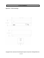
Appendix A Outline drawings............................................................................................ 64
Appendix B: Card Formats ................................................................................................. 65
ISO .................................................................................................................................. 65
AAMVA ........................................................................................................................... 66
Copyright © 2010, International Technologies & Systems Corporation. All Rights Reserved
4 of 66
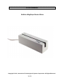
ID TECH EzWriter
EzWriter MagStripe Reader Writer
Copyright © 2010, International Technologies & Systems Corporation. All Rights Reserved
5 of 66
ID TECH EzWriter
Introduction
EzWriter is a personal computer peripheral device for reading and writing magnetic stripe
card data. WorkShop is the companion software product, which provides operation of
EzWriter through a Personal Computer. The MagStripe cards must meet the ISO 7811
standards for an ID1 card (typical credit card). Cards are manually swiped through the slot
to perform a reading and/or writing operation. Data can be written and read verified with
one swipe. The Reader/Writer supports magnetic stripe track formats defined either by an
established industry standard or by a user (customer defined) data format. All formats use
F/2F data bit encoding (writing) and either 210 or 75 bits per inch (BPI) data densities. The
EzWriter can read and write both High coercivity and Low coercivity (Hi-Co & Lo-Co)
magnetic stripes.
The enclosure is a die cast metal housing that provides weight and stability for excellent
performance. There are two communication interfaces, either RS232 or USB, available
through an attached six-foot cable. There are two command protocols available for
EzWriter operations; the IDT protocol is the default and the AMC protocol is selectable
using the Workshop application on the Companion CD. A separate power adaptor is
required to supply the power needed for writing cards.
There are three Sections to this document:
The First Section provides Quick Start information covering EzWriter installation and
installation of ID TECH’s WorkShop Utility Application software. WorkShop operates with
both RS232 unit and USB units and provides easy to use commands for performing all read
and write functions. A simple example of WorkShop operation is given in this section. The
example performs the two most basic operations, writing and then reading on a Lo-Co or
Hi-Co magnetic stripe card.
The Second Section provides operation details for all the WorkShop functions.
The Third Section is the Technical Guide for the Reader/Writer. This section provides the
product specification, commands, and related information. There are two command sets
supported by EzWriter units supplied after November of 2006. The default command set is
based on prior IDT products; the new command set is based on the Universal Serial
Interface, which supports the original AMC products operations. The AMC command set is
provided to support backward compatibility with previous software products & applications.
The Magnetic Stripe Reader & Writer is RoHS compliant.
For additional information, contact us or visit our website.
ID TECH
P 714.761.6368
www.idtechproducts.com
Copyright © 2010, International Technologies & Systems Corporation. All Rights Reserved
6 of 66
ID TECH EzWriter
Quick Start
This Quick Start section covers EzWriter installation and WorkShop software installation. A
simple example is given to introduce WorkShop & EzWriter operation. The example guides
an operator through the process of writing a few characters onto a magnetic stripe card and
then through the process of reading the card to see the written data.
Installing WorkShop Software
The WorkShop software runs on Microsoft Windows platform for EzWriter with an RS232 or
USB communication interface.
All the software is provided on a CD or is available on the ID TECH website in the form of a
downloadable ZIP file. The downloaded Zip file has internal files, which must be extracted
before using. Install WorkShop on a PC by Running the Setup file located on the CD or
located in the extracted ZIP files. Follow the directions and process in the installation
wizard. The result is a “IDT EzWriter WorkShop Vx.x” menu item added to the Programs
menu in the Windows START menu. A file folder is added to the Program Files folder on
the local hard drive. The new folder name is “IDT EzWriter Workshop”. This folder
contains the Workshop application and support files for Reading and Writing cards.
Installing EzWriter
EzWriter is used in an indoor environment. Locate the EzWriter where it is convenient to
operate and protected from dust and liquids. For right-handed persons, swiping a card is
most convenient from right to left. Position the EzWriter so the flared card entrance is on
the right. A 24VDC power adaptor is provided. The adaptor input voltage range is 100 to
240VAC and can be used in most countries. The line power plug may need to be adapted
to the power outlet connector. Remove the power adaptor from the packing box. Wait to
connect the power adaptor until all the other connections are made.
The communication type can be RS232 or USB-RS232. Proceed to the Communication
Interface section corresponding to the interface of your EzWriter unit.
Communication Interface
RS232
The EzWriter has a communication cable with a DB-9 connector that fits most computer
serial (RS232) COM port connectors. An adaptor (not supplied) can be used to adapt to a
DB-25 connector if necessary. See the Specifications, Interface Section for port settings.
Connect the DB-9 connector to the PC and insure it is fully seated. Connect the power
adaptor output to the power connector on the back of the DB-9 housing. Finally, connect
the power adaptor to the AC line power outlet. When power is applied, the LED on the
Reader/Writer is orange for a moment and then becomes green. If the LED does not light,
check the connections and the availability of power from the power outlet.
Copyright © 2010, International Technologies & Systems Corporation. All Rights Reserved
7 of 66
ID TECH EzWriter
USB-RS232
The USB interface operates though a serial COM port like an RS232 device. The USB
communication uses a special USB-RS232 driver included in the supplied CD or is
available from the ID TECH website. EzWriter is a “Self-Powered” USB device and must
be powered using the 24VDC power adaptor provided with EzWriter.
The USB cable has two connectors at the cable’s end. One connector is for the PC USB
connection and the other is for the power adaptor connection. Connect the EzWriter USB
connector into the PC and insure it is fully seated. Connect the power adapter output to the
power adaptor connector on the USB cable. Finally, connect the power adaptor to the AC
line power outlet.
When power is applied, the LED is orange for a moment and then becomes green. If the
LED does not light, check the power adaptor connections.
When the USB connection is recognized by the operating system for the first time, a Found
New Hardware message is given. The operating system must install USB drivers in the
PC. The drivers provide the communication link between the PC and EzWriter.
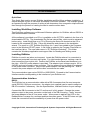
When the New Hardware Wizard window appears, follow the wizard directions to install the
USB-RS232 drivers into the PC. The drivers are available online as Signed drivers. If an
internet connection is available to the PC or the Workshop CD is available and installed in
the CD drive, then perform “Install the software automatically (Recommended)” selection.
Otherwise, select the “Install from a list or specific location (advanced)” option. For the
advanced option, Workshop software must be installed first to have the drivers on the PC
hard drive. If Workshop is not already installed, stop here and install Workshop as
instructed above. Workshop software is available on the ID TECH website.
Copyright © 2010, International Technologies & Systems Corporation. All Rights Reserved
8 of 66
ID TECH EzWriter
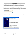
If the Workshop CD is installed or the PC has an internet connection, then select the
“(Recommended)” button and Click Next > to continue. The wizard searches for and
installs the first driver. Close the Wizard by clicking “Finish”.
The New Found Hardware Wizard appears a second time to install a second driver.
Repeat the same process again to install the second driver. When both drivers are
installed, the process is complete. The USB communication interface is ready for operation
when the “Found New Hardware” bubble appears with the following notice.
If the Workshop CD or internet connection are not available, select the “(Advanced)” button
and Click Next > to continue.
Copyright © 2010, International Technologies & Systems Corporation. All Rights Reserved
9 of 66
ID TECH EzWriter
Select “Browse” & establish the path “C:\Program Files\IDT EzWriter Workshop\USB
Driver”. Select next and the Wizard locates and loads the driver from the folder.
The wizard searches for and installs the first driver. The New Found Hardware Wizard
appears a second time to install a second driver. Repeat the same process again to install
the second driver. When both drivers are installed, the process is complete and the USB
communication interface is ready for operation.
Copyright © 2010, International Technologies & Systems Corporation. All Rights Reserved
10 of 66
ID TECH EzWriter
Using WorkShop
In the “Programs” tab of the Windows START button, double click the “IDT Reader/Writer
WorkShop” to RUN the application. The Password Dialog Box appears the first time the
installed application is RUN. Select a password, confirm it, and click OK. Each
subsequent time WorkShop is RUN, a dialog box (shown below) opens to request the
password. The password is required each time the WorkShop is launched. The default
password is “idtech”.
One of the protocol options buttons is already selected; this indicates the protocol in which
EzWriter is already set. Change the protocol options if desired. The IDTECH protocol is
recommended for use with Workshop. The IDTECH protocol allows more function
selections. See the Communication Modes section on page 16.
If the “AMC Protocol” box is checked and used the first time since using IDTECH protocol,
an “Input Port Number” (1 to 10) message window appears. The user must enter the
communication port number. The port number can be found by going to “System
Properties”, “Hardware Folder”, “Device Manager” window, and in the Ports.
WorkShop checks the communication link with the EzWriter both before the password
window and after. During this process, the “Connecting the unit” window is displayed. The
WorkShop window appears when the communication link is verified. If there is an error,
check the Reader/Writer LED for a Green (power on) condition and verify the
communication connections.
Copyright © 2010, International Technologies & Systems Corporation. All Rights Reserved
11 of 66
ID TECH EzWriter
Notice: The “Connecting the unit. Please wait…” notice may appear several times as
Workshop establishes communication with EzWriter. There is a delay period
between the “Connecting” notice closing and the “Workshop” window appearing.
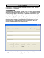
The initial WorkShop Window is shown above with the firmware version shown in the
Message text box. The latest version may not match the version in the screen above.
Copyright © 2010, International Technologies & Systems Corporation. All Rights Reserved
12 of 66
ID TECH EzWriter
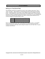
Writing on a Card (Quick Start)
The WorkShop window has a separate text box for each magnetic stripe track: Track 1,
Track 2, & Track 3. Above each box, a label shows the track number and the encoding
format. Characters that are to be written on the magnetic stripe are entered into the text
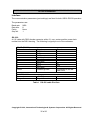
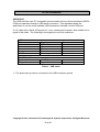
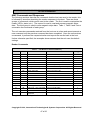
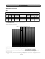
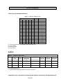
boxes. In this example, the card is written with the ISO standard format. The chart below
shows the number of characters that can be written on each track of an ISO formatted card.
Entering more characters than allowed for the track or entering alpha characters into a
numeric characters only track causes an error.
Track
1
2
3
Number of Characters & Type
76 Alphanumeric Characters
37
Numeric Characters
104
Numeric Characters
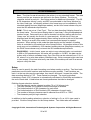
Enter some characters to be written on the card into the track text boxes. For example,
enter your name in the Track 1 box, then tab down to the Track 2 box and enter the
numbers 0 through 9, and finally, enter a string of number 3’s in the Track 3 box. See the
example window below.
Copyright © 2010, International Technologies & Systems Corporation. All Rights Reserved
13 of 66
ID TECH EzWriter
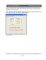
The WorkShop default setting is for Lo-Co magnetic stripe cards. For Hi-Co magnetic
stripe cards, click the “Setup” button in the lower right corner of the WorkShop window.
Then click the High Coercivity check box. See the example with the Hi-Co box checked.
Do not change any other selection. Click OK to return to the WorkShop window.
There are two sample cards provided with the EzWriter. One is a Lo-Co type and the other
is a Hi-Co type. Either one or the other can be used. The coercivity in the Setup window
must be set to match the card type used. Note: the EconoWriter product supports only low
coercivity card writing; selecting the High Coercivity check box does not affect EconoWriter.
Copyright © 2010, International Technologies & Systems Corporation. All Rights Reserved
14 of 66
ID TECH EzWriter
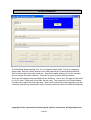
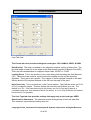
Click the Write button. The “Write Card” window appears as shown on the previous page.
Caution: When the “Please Swipe a Card” window has a yellow background color and
when a card is swiped through the slot, the EzWriter changes data on the magnetic stripe.
When there is no data in a Track text box, then that specific track is not written and any
data already on that track is not changed or erased.
Copyright © 2010, International Technologies & Systems Corporation. All Rights Reserved
15 of 66
ID TECH EzWriter
Swipe a card at a moderate rate through the card slot. A moderate rate is equivalent to
moving a card from the entrance to the exit in about 1/2 second.
When swiping a card, the magnetic stripe must be in contact with the magnetic heads. The
heads are on the side with the logo labels. The card must be held so the stripe is down
and facing toward the logo when swiped through the slot from right to left.
The card must be registered (held) to the reference surface at the bottom of the card slot.
The card must be swiped through the slot without tipping or stopping and moved with one
steady movement all the way through the slot. The operation is unidirectional; the
operation is only in the forward direction starting from the card slot’s tapered end. The
EzWriter does not function with cards swiped in the reverse direction.
The Message text box at the top of the WorkShop window shows “Write(1) OK!”. If three
cards were swiped, all three have the same written data and the Message text box shows
“Write(3) OK!”. End the card writing process by click the “End” button in the “Please Swipe
a Card” window.
Note: The EzWriter has two magnetic heads; one is for writing and the other is for reading.
The Reader/Writer performs a read after write operation when writing cards. When a card
is swiped, the card passes over the write head first and then the read head. This read after
write feature is how the EzWriter determines a Write OK or a Write Error condition.
Reading a Card (Quick Start)
When the Read button is clicked and a card is swiped through the card slot, the EzWriter
reads all tracks. When reading a card, the coercivity of the magnetic stripe has no
importance. The read operation is the same for all card coercivities.
To read the card just written, Click on the Read button and swipe the card. The Track text
boxes fill with the data read from the card tracks. Empty card tracks have no data to be
display and those text boxes are empty. Cards can be swiped and read with no limit. The
Track box data is refreshed each time a card is swiped and there is no read error. To end
the reading process, click the “End” button in the “Please Swipe a Card” window.
This concludes the Quick Start Section. The basic functions of loading the WorkShop
application, installing the EzWriter, card writing, and card reading have been demonstrated.
The next sections are the User Manual for the WorkShop Utility. There is practical
Magnetic Stripe information in the Appendix B.
Copyright © 2010, International Technologies & Systems Corporation. All Rights Reserved
16 of 66
ID TECH EzWriter
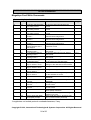
WorkShop Utility
The EzWriter and WorkShop software together provide the card reading & writing functions
most often needed for magnetic stripe use. These functions & operations are available
from a single WorkShop window. Following is a summary of the WorkShop functions:
WorkShop Utility Functions
Write
Read
Compare
Erase*
Sequential Write
Write from File
Read to File
Database Write
Card Type
- ISO
- AAMVA
- USER
- RAW*
- PASS BOOK
Setup
- Leading Zero
- BPI Setting
- Set Coercivity†
- Start Sentinel*
- End Sentinel*
- Bits/Character
- Parity*
- Default
Writes data to a card in the Card Type format
Reads card data and displays the data in Track boxes
Compares multiple cards to a single reference card
Erases the selected tracks of data on a card
Writes both fixed and/or sequential data to a card
Writes to each card the next record from a pre-formatted data file
Reads a card & saves the card data as a record into a data file
Writes cards from a database CSV file & Usage file
Provides card format selection based on Setup menu or Standard
Selects 7811 ISO Standard card format
Selects AAMVA standard, based on ISO Standards
Selects the card format from settings in Setup USER tab
Reads & writes data and displays in a Hexadecimal format
Reads & writes data on a passbook
Provides selections & settings of different card formats
Sets number of leading zeros before the Start Sentinel
Selects individual track data density (75 or 210 bits/inch)
Sets the writing coercivity to High or Low for all tracks
Selects the Start Sentinel character for the individual tracks
Selects the End Sentinel character for the individual tracks
Selects the number of bits per character for individual tracks
Selects character parity bit logic for individual tracks
Resets the parameters & settings to the standard norms
* These functions are not supported when the “AMC protocol” is selected.
† Low Coercivity units cannot be set to Hi Coercivity operation
This document assumes the user has basic knowledge of magnetic stripe track densities,
data formats, character formats, and the like. Basic magnetic stripe information is given in
Appendix B.
Communication Modes
Workshop has two communication protocols the IDTECH or the AMC protocol. Only the
IDTECH protocol is described here; it is the default protocol setting. The Workshop
Password entry Window allows selection of either the IDTECH or the AMC protocol. Select
the protocol to be used. The AMC protocol emulates the AMC USI communication
protocol. After one of the protocol Radio buttons is selected, Workshop configures
EzWriter for that protocol; the protocol remains fixed in EzWriter unless changes by
Workshop. The AMC protocol mode does not support all functions provided by the
Copyright © 2010, International Technologies & Systems Corporation. All Rights Reserved
17 of 66
ID TECH EzWriter
IDTECH protocol mode; see the asterisks items in the Functions List above. Using the
IDTECH protocol is recommended.
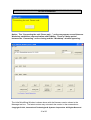
WorkShop Window
WorkShop operates from this window. There are several areas (boxes) within the window.
Above each box is a descriptive label. Starting from the top left, the Message box provides
a “result” of the last operation. The information in the Message box shown below is the
result of opening the connection to a Reader/Writer and it shows the firmware version
number & date. The Card Type box on the right indicates the current selected data format
for reading or writing a magnetic stripe. This is the only box with a pull-down menu. More
information is provided in a following section. The next three boxes are text boxes; there is
one for each track. Either the text boxes provide a display of the data characters to be
written to a stripe or the data read from a stripe, depending on the current function being
performed. If there is no data in a text box, then that corresponding track is not active
during the operation. There are ten function buttons along the bottom. Each of the
functions is explained separately in the following sections.
Copyright © 2010, International Technologies & Systems Corporation. All Rights Reserved
18 of 66
ID TECH EzWriter
Message Box
The Message Box always displays the result of the last action. Mostly, it indicates a
successful read or a successful write operation after swiping a card through the slot. When
the operation can be performed on more than one card, the result message provides a
count of successful card operations.
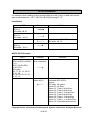
Card Type
This provides a selection of reading and writing track formats. Track formats are the
combination of the track density, bits per character, selection of Start & End Sentinels, and
other parameters. The Card Type pull down menu has four selections: ISO, AAMVA,
USER, RAW & PASS BOOK. Each card type is explained below. The settings for each
type are available in the Setup window. See the Setup section & Appendix B for more
information.
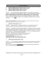
ISO - The ISO format follows the requirements given in ISO Standard 7811-6 and
earlier versions. Density is in bits per inch. Bits per character include a parity bit.
The number of Data Characters given does not include the Start Sentinel (SS), the
End Sentinel (ES), or the Longitudinal Redundancy Character (LRC). The SS, ES,
& LRC are automatically inserted into the data when writing to the card tracks.
Track
Density
Bits per Character
1 IATA
210
7 bits per character
ISO Maximum number
of Data Characters
76 Alphanumeric
2 ABA
75
5 bits per character
37 Numeric
3 Thrift
210
5 bits per character
104 Numeric
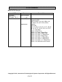
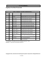
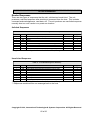
AAMVA - The AAMVA format follows the same character formats as defined by the
ISO Standards. The maximum number of Data Characters for Tracks 1 & 3 is
different from the ISO format and Track 3 is alphanumeric, following the same format
as Track 1. The number of Data Characters shown does not include SS, the ES, or
the LRC characters.
Track
Density
Bits per Character
1 IATA
210
7 bits per character
AAMVA maximum number
of Data Characters
79 Alphanumeric
2 ABA
75
5 bits per character
37 Numeric
3 Thrift
210
7 bits per character
79 Alphanumeric
Copyright © 2010, International Technologies & Systems Corporation. All Rights Reserved
19 of 66
ID TECH EzWriter
User - The User format allows data to be written in a non-standard format. The data
density and bits per character are defined in the Setup Window. The bits per
character include a parity bit. See Setup section for additional information. The SS
& ES characters, density, parity, and BPC are selectable in the Setup Window for
the User Card type. Information written in this format may not be readable by ISO
standard reading devices (MagStripe readers), as the User format chosen may not
meet the ISO standards requirements.
RAW – This is not a true “Card Type”. This is a data decoding & display format for
the three tracks. The text boxes display data in “raw binary” using the hexadecimal
number format. Data read from a card is decoded into binary starting with the first
“binary one” bit (usually the first bit of a start sentinel). All the bits (in Hex) are
displayed and including approximately fifteen trailing zero bits at the end of the track
data. Writing to a card in this mode is not recommended except for special
purposes. When writing in this mode the data density and the number of leading
zeros is controlled by the selections in the Setup Window. Information written in this
mode may not be readable by ISO standard reading devices (MagStripe readers), as
the RAW format chosen may not meet the ISO standards requirements.
PASS BOOK – In this format, users can write to any selected tracks, not restricted
to IBM or ISO passbook spec. All tracks will be written in 210 BPI, the data can be
written with or without redundant copy. Sync Zero Bits can be selected from 0, 26, or
60, where 0 is to write data without redundant copy. Write command might need one
or two swipes. If first time write/verify was failed, the workshop will ask for a second
swipe to verify the data.
Setup
Setup is used to specify the track formatting used when reading or writing. Two fixed track
parameters are the track locations and the data encoding method. Track locations are
track 1 at the top side near the card edge, then track 2 and track 3 toward the middle. The
data encoding method is F/2F. These cannot be changed. The track longitudinal
redundancy check (LRC) character is automatically calculated by WorkShop and added to
the end of track data. Listed below are format parameters that can be changed:
EzWriter format selections include:
o The Data density can be selected as either 75 or 210 bits per inch.
o The Start Sentinel (SS) location from the card edge is selected.
o The limited selection of SS characters for each track.
o The limited selection of End Sentinels (ES) characters for each track.
o The number of bits per character can be selected from 4 BPC to 7 BPC
o The character parity bit logic selection
In addition to the formatting selections, selection of writing Lo-Co or Hi-Co type cards is
provided. Click the Setup button for the Setup window. Two folder tabs are available.
Copyright © 2010, International Technologies & Systems Corporation. All Rights Reserved
20 of 66
ID TECH EzWriter
There are “default” buttons in each tab window; these default buttons force the format
settings in the window to be reset to the standardized ISO settings. See Appendix B for
additional technical information.
Note: Always use the Default Setup settings unless there is a known, specific, and
understood reason for not using the default settings.
Format Tab View
Copyright © 2010, International Technologies & Systems Corporation. All Rights Reserved
21 of 66
ID TECH EzWriter
User Tab View
The Format tab view provides settings for card types: ISO, AAMVA, USER, & RAW.
Data Density: The data is encoded on the magnetic stripe as a string of binary bits. The
physical length of each bit on the stripe is the data density specified in Bits per Inch (BPI).
There are two data densities for magnetic stripe cards: 210 BPI or 75 BPI.
Leading Zeros: This is the number of zero value binary bits preceding the Start Sentinel
(SS). These zeros are used for synchronizing the reading circuits and bit-decoding
algorithm. These zeros are required. The number of zeros required is based on the data
density and the ISO required distance of the SS from the edge of the card.
High Coercivity: This is a check box in the Format window. The EzWriter writes on HI-Co
or Lo-Co magnetic stripes. This box selects the coercivity the EzWriter is to use. The
default is Lo-Co. If the card coercivity is not known, use Lo-Co first and if there is a
consistent write error, then switch to the Hi-Co setting. A Lo-Co Only EzWriter Unit cannot
be set into Hi-Co operation.
The User Type tab view provides settings that apply only to the card type USER.
Start Sentinel Characters: This character marks the beginning of the track data field.
This character is preceded by leading zero bits.
Copyright © 2010, International Technologies & Systems Corporation. All Rights Reserved
22 of 66
ID TECH EzWriter
End Sentinel Characters: This character marks the end of the track data field. There is a
Longitudinal Redundancy Check character (LRC) following the end sentinel. The LRC is
used for error checking the data bits. The LRC is calculated by WorkShop and added
automatically when writing to a card. There are trailing zeros following the LRC.
Bits per Character: The bits per character can be selected from 4 BPC to 7 BPC. The
standards are 5 BPC for numeric characters including the parity bit or 7 BPC for
alphanumeric characters including the parity bit. See Appendix B for the character tables.
Parity: The character parity bit logic can be selected. The default and standard selection
for 5 and 7 bit characters is “Odd” parity. The parity bit for each character is added by
WorkShop as the character is written on the card. For 4 or 6 BPC characters, parity must
be “None”.
Write
This function writes data to the magnetic stripe when the card is swiped through the slot.
WorkShop writes the data in the track text boxes together with standard or user defined SS,
ES, and LRC each time a card is swiped through the slot. A prompt window opens to
inform the user to swipe a card for writing. The Message box at the top of the WorkShop
window shows the result for each card swipe, either the card was written OK or an ERROR
was the result. The Message box also gives the count of the cards that have been swiped
and written with no errors. For sequentially changing numbers, see Sequential Write
below. To finish the Write process, click on the End button to close the prompt window.
Copyright © 2010, International Technologies & Systems Corporation. All Rights Reserved
23 of 66
ID TECH EzWriter
Caution: When a magnetic stripe track is written, the original data on the track, if any, is
replace by the new data. An individual track can be changed without effecting data on the
other tracks. However, if the Track text box is empty, WorkShop does not erase the
original data, if any, in that track.
Read
This function reads data from the magnetic stripe on a card , including SS & ES, when it is
swiped through the slot. The read data is shown in the track text boxes. There is a prompt
window opened to inform the user to swipe a card for reading. The Message box shows
the result for each card swipe, either the card was read OK or there was a reading ERROR.
The count of the number of cards read is shown. There is no limit on card swipes; each
card is read and the card data shown. To finish the Read process, click on the End button
to close the prompt window.
Compare
This function compares card data from one card with data read from other cards. The initial
data is read from a card and saved in the track text boxes. Comparisons of data read from
subsequent cards are made with the initial data saved in the text boxes. A comparison is
made each time a card is swiped. This function is useful for checking cards to a standard
card. When the Compare button is clicked, the user is prompted to swipe the card having
the initial comparison data. After the initial data is read, the prompt changes and the user
is prompted to swipe cards; these cards are read and their data compared with the first,
initial card data. The result of each comparison is shown in the Message box. To finish the
Compare process, click on the End button to close the prompt window.
Erase
This function can be used to erase data on the card tracks. The EzWriter must be set for
the correct operating coercivity of the card(s) to be erased. See the Setup section for
information on selecting the writing coercivity. Individual tracks can be selected from the
pop up track selection window. Select the track boxes to be erased; close the window.
Another prompt window appears to prompt a card swipe. Only the selected tracks are
erased. The non-erased tracks retain their data. The message box shows the results.
After erasing, WorkShop prompts a swipe of another card for erasing. To finish the Erase
process, click on the End button to close the prompt window.
Warning: If the EzWriter is set for Hi-Co operation and a Lo-Co card is swiped, all
data on the Lo-Co stripe may be erased.
Copyright © 2010, International Technologies & Systems Corporation. All Rights Reserved
24 of 66
ID TECH EzWriter
Sequential Write
This function allows creation of a special sequential number “field” in the Track text boxes.
The sequential field can be one or more number characters. The sequential number field
can be the only characters written in the track or the sequential number can share the track
with other “fixed” data (numbers and/or alpha characters) in the track. Any fixed data in the
Track text boxes can be entered before or after the sequential number field is entered.
Typically, the fixed data is entered first and then the sequential number field is added to the
fixed data. The same sequential number can be in one track or the same number can be in
all three tracks. Only one sequential number field is allowed per track. The sequential
number field(s) must allow the minimum number of sequential digit spaces as needed for
the number of digits to be sequenced. As an example, the number 150 must have a
sequential number field of three characters minimum or more. The number of digits in the
sequential number fields can be different for each track. The sequential number field
operates with numbers only.
Click the “Seq. Write” Button. Establish the sequential number field by positioning the
curser at the sequential number field starting location and click. The sequential field can
start at any location within the data, if any. WorkShop prompts the user to enter the
sequential field digit indicators (x) by typing any printable character on the keyboard.
Workshop inserts the “x” characters, which represent each numerical digit in the sequential
field. This process can be used on one track or can be repeated for each track. When the
field selection is completed, close the prompt box and another prompt box is opened for
selection of the starting (initial) value of the sequential number and selection of the number
of cards to be written. Insert the values and click OK. The initial starting value is
automatically inserted into the sequential field; the balance of the field is filled with the zero
digits. WorkShop prompts the user to swipe and write the first card. After each swipe,
WorkShop displays the result. If write operation is successful, WorkShop increments the
sequential number and prompts for writing the next card. If there is a failure, WorkShop
gives a warning and prompts for writing the same number. Other data in the track fields (if
any) is not altered. When the “Number of cards to be written” value is reached, the
Sequential Write process is ended. Close the Sequential Write Complete window.
Copyright © 2010, International Technologies & Systems Corporation. All Rights Reserved
25 of 66
ID TECH EzWriter
Read & Writing File Operations
The Read & Write File operations provide a means to read cards, saving the read track
data to a file and using the same file to write the same information to a new set of cards.
The cards read are a data source for the opened file. One card or a sequence of cards can
be read. Each card read creates a separate record within the file. The records are added
to the file in the sequence they are read. The number of records added to the file equals
the number of successfully read cards. When writing from the file, each card is written with
the data from one of the records starting from the first data record and written in the same
order as cards were read.
The Reading & Writing File Operation files are kept in the default file folder “To From Files”,
which is a sub-folder in the “IdtMsrwWorkShop” in the Program Files folder. The To From
Files can be moved and accessed from other folders. The files have a file extension that
matches the “Card Type” used to create the original file. Card Type is defined in the upper
right hand menu box on the Workshop main window. The card type cannot be mixed; the
card type must be consistent within a file.
Read To File
Selecting this function generates a Windows Explorer window to open an existing data file
or create a new data file. If an existing file is selected, the previous data is maintained and
the new card data is appended as cards are swiped. After a file selection is made, a
second window opens to prompt the swipe of a card. The reading result is shown in the
Message box for each swipe. If there is a read error, the card data is not saved; swipe the
card again to enter the card data into the file.
Write From File
This functions Writes data from a named file to a card. The card data is in a file records
created by the “Read To File” operation as described above. The Write To File function
prompts the user to open an existing data file. When a file is selected, the user is prompted
to swipe a card (or sequence of cards); each card is written with the next data record from
the file. The Message box shows the writing result for each card. If there is a write error,
the current data record is used until the record is successfully written to a card. Cards are
written until the last record is used. When the last data record is written, a prompt informs
the user the writing process is finished.
Copyright © 2010, International Technologies & Systems Corporation. All Rights Reserved
26 of 66
ID TECH EzWriter
Database Application
WorkShop does not provide direct access to industry standard data base applications. The
word “database” is used here for the convenience of describing the WorkShop function &
operation, which emulates a database process. The WorkShop Database Application
provides a method for writing on cards using data from two files. The two files are the
Database file, which is a csv type file and the Usage file, which is a txt type file. The csv
file can be an extracted or exported file from a standard database application.
Both files are used together and are required for the Database Application card
writing process. Both files must have the same filename and both files must be
located in the same file folder.
The Database file shown in the example is an Excel csv file type. The file was created
using Excel; the Excel file was saved as a .csv type. Any application program that can be
used to create the rows and columns of information to be written to cards can be used to
produce the WorkShop Database file. The final database file must be saved as a csv type
file for WorkShop database operations.
Copyright © 2010, International Technologies & Systems Corporation. All Rights Reserved
27 of 66
ID TECH EzWriter
The Usage file in this example was created using Notepad. The Usage file has two
functions: it may contain the Card Type and card Setup format rules “[SETTING]”; it must
contain a data definition “[DATA]”. The Card Type and card format SETTING parameters
are the same Card Types as in the WorkShop window and the same formatting parameters
found in the WorkShop Setup tabs. The SETTING rules, if used, are used for all cards
written. In the example shown, no SETTING rules are specified; they are ignored by the
WorkShop database function because of the double forward slashes placed at the
beginning of each line in the SETTING section. If no SETTING rules are specified, the
WorkShop database function uses the default ISO 7811 formatting norms.
The information (data) written to a card can has two sources. There is a fixed data source
and a variable data source. The DATA definition in the Usage file specifies the fixed card
data information and specifies the source of the variable card data information. The Usage
file DATA definition has three rows. Each row specifies the data to be written on one track;
the first row specifies the data for track one, the second row for track two and the third row
for track three. Each card is written as specified by the DATA definition; each card written
can have unique data written on the tracks because the variable data is being sourced from
the database file.
The Data Usage file Fixed data is defined and directly used from the Usage file as
character fields written to a card; the fields cannot contain characters not allowed for the
defined track format. In other words, tracks written with five bits per character can use only
Appendix B, Table 2 characters; likewise, tracks written with seven bits per character can
use the character set in Appendix B, Table 1.
Variable data written to the cards is specified by two characters that define the Data
Columns in the Database file. The two characters have a fixed format. The first character
is a lower case “f” followed by a second “Column” letter (a through z). The variable names
correspond to the column letter in an Excel csv file. The Data Column variable data and
the Usage file fixed track data can be mixed in the Usage file DATA definition.
An example database is provided with the WorkShop Utility files. That example is used
here to show the format. The example does not define the SETTING rules; the rules are
shown and are ignored by the WorkShop Database Application (any line in the User file
that starts with two forward slash characters // is ignored). When no SETTING rules are
defined, ISO Standard parameters are the default. The DATA definition specifies the data
to write on the three tracks. When there is no data specified for a track, the track is not
written. The csv file has 10 rows; therefore, ten cards can be written. Each card is written
with variable data from one of the ten rows, starting with row one.
Copyright © 2010, International Technologies & Systems Corporation. All Rights Reserved
28 of 66
ID TECH EzWriter
The data written on the first card is shown. The number in brackets { } indicates the card
track number:
{1}
{2}
{3}
SLAM-DUNK~SPORTS~EVENT=DAVID=12340999
12340=999=250205
(nothing is written on track three)
Using only track 1 as the example, the “SLAM-DUNK SPORTING EVENT=” is a fixed card
data field; “DAVID” is a variable field from the database file as defined by “fa” (meaning
“field a”); the next “=” is a fixed field; and “12340999” is two variable fields from the
database file as defined by “fbfc”. The next card written has the same fixed field data and
new variable field data based on row two in the csv file. Defined in row two is the name
“MICHAEL” and the card number & validation number is “12341989”. The data in track 2 is
a variable and remains the same for all cards because it is defined as the same in the
database file. See the example here for the second card written:
{1}
{2}
{3}
SLAM-DUNK~SPORTS~EVENT=MICHAEL=12341989
12341=989=250205
(nothing is written on track three)
The database Usage file is shown on the following page. This file can be copied from the
CD and then modified for other database applications. This file is also located on the hard
drive in the Workshop folder.
Copyright © 2010, International Technologies & Systems Corporation. All Rights Reserved
29 of 66
ID TECH EzWriter
/////////////////////////////////////////////////////////////////////
// ID TECH Sample database Usage file
// The "//" at the beginning of a line specifies the line is a comment and line content
// is NOT used for database functions or operations.
[SETTING]
// This is the SETTING section. In this example, all the lines begin with "//", so the
// content here is for your reference & NOT used by the database. When no settings
// are specified the CARDTYPE default is, in all cases, the ISO format. Remove the "//"
// from the lines & change values only when a non-ISO format is wanted.
// Used only one of these lines to select a non-ISO format.
//CARDTYPE=USER
//CARDTYPE=AAMVA
// In the next 3 lines the ISO default BPI is shown. Change settings only if needed.
// The tracks can have any mix of 75 or 210 value. Only "75" or "210" is a permitted value.
//BPI1=210
//BPI2=75
//BPI3=210
// Use the following settings ONLY when "CARDTYPE=USER" is selected. Adjust the
// parameters to specific values for the application. The ISO CARDTYPE format setting
// is shown as the example. Only a specific, limited set of values are permitted. Check
// the WorkShop "Setup" window & "USER" folder for the permitted values.
//BPC1=7
//BPC2=5
//BPC3=5
//PARITY1=ODD
//PARITY2=ODD
//PARITY3=ODD
//SS1=%
//SS2=;
//SS3=;
//ES1=?
//ES2=?
//ES3=?
// The DATA section defines the fields that apply to each track.
[DATA]
Trk1:SLAM-DUNK SPORTS EVENT=fa=fbfc
Trk2:fb=fc=fd
Trk3:
//end
Copyright © 2010, International Technologies & Systems Corporation. All Rights Reserved
30 of 66
ID TECH EzWriter
The Excel csv Sample file has the following variable data fields:
This same file can be opened from Notepad, as shown below:
The filename extension, .csv, means a comma separated values file. As seen in Notepad
above (and like in the Excel example), each row is one record of variable information
written on one card. Commas separate each row into columns. Each row must have the
same number of columns. Most text editors can create, view, or edit a CSV file.
Copyright © 2010, International Technologies & Systems Corporation. All Rights Reserved
31 of 66
ID TECH EzWriter
EzWriter Technical Reference Guide
Introduction
This section of the User Guide pertains to the information for communication directly with
the EzWriter. This information is intended to support the development of application
specific software that directly operates with the EzWriter. This information is not need
when using the ID TECH supplied WorkShop Utility.
Description
The Reader/Writer reads and writes magnetic stripe cards when the cards are swiped
through a card slot. The housing encloses the read head and the write head. Both are
mounted to a rail assembly. The rail assembly contains the card vertically and has a
reference surface, which aligns the magnetic stripe with the heads for track locations. The
heads are precision mounted to meet the ISO Standards requirements.
Adjacent to the write head is an optical encoder, which provides timing signals for writing to
cards at data densities of 210 and 75 Bits per Inch (BPI). The encoder has a rubber roller
that is moved by the card when the card moves past the write head.
The metal housing has an operation LED. The LED is a single lens, capable of generating
three colors red, orange, and green. See the operation section for the description of
operations associated with the color.
The card slot has a write head and a read head. The space between the two heads allows
for writing data to the magnetic stripe and then reading the data in a single card swipe.
This is an advantage for checking the integrity of the data being written.
Accessories
80058801-001
AC0005-9
80005211-001
80005211-002
80058801-00x
WorkShop Software Application Utility
Power Adaptor, 100-240VAC input, 24VDC @2.5A output
Sample Magnetic Stripe Card, Lo-Co stripe
Sample Magnetic Stripe Card, Hi-Co stripe
Companion CD (ask for latest revision)
Copyright © 2010, International Technologies & Systems Corporation. All Rights Reserved
32 of 66
ID TECH EzWriter
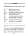
Terms & Related documents
AAMVA
Lo-Co card
Hi-Co card
ASCII
BPI
BAUD
Coercivity
CDL
EzWriter
Host
IPS
ISO
Hex
LED
LRC
MSR
PC
PCA
RS232
Slot
Swipe
USB
WorkShop
American Association or Motor Vehicle Administrators
low coercivity magnetic stripe card.
high coercivity magnetic stripe card
American Standard Characters for Information Exchange
Bits Per Inch
Roughly the RS232 communication in bits per second
The resistance of a magnetic field to change, in Oersted
California Drivers License format
Trademark name for the MagStripe Reading & Writing product
The Personal Computer to which the Reader/Writer is attached
Inches Per Second
International Standards Organization
Hexadecimal, base 16 numbering system
Light Emitting Diode
Longitudinal Redundancy Check a form of error check character
Magnetic Stripe Reader
Personal Computer (see Host)
An assembled Circuit Board
Reference Standard for serial asynchronous communication
The card path opening for passing a card through an EzWriter
The operation of moving a card through the EzWriter slot
Universal Serial Bus—a high speed connection to the host
Trademark name for the EzWriter software application
AAMVA
Best Practices Guidelines for the Use of Magnetic Stripes
ISO 7810:1995
Identification Cards - Physical characteristics
ISO/IEC 7811-2:1995
Identification Cards - Part 2: Magnetic stripe
ISO/IEC 7811-3:1995
Identification Cards - Part 3: Embossed characters, ID-1 cards
ISO/IEC 7811-4:1995
Identification Cards - Part 4: Location of read-only Tracks 1&2
ISO/IEC 7811-5:1995
Identification Cards - Part 5: Location of read-write Track 3
ISO/IEC 7811-6:1996
Identification Cards - Part 6: Magnetic stripe - High coercivity
Copyright © 2010, International Technologies & Systems Corporation. All Rights Reserved
33 of 66
ID TECH EzWriter
Specifications
Environmental
This product is to be used in an indoor environment.
Operating temperature:
0ºC to 50ºC, 5 to 95% relative humidity, non-Condensing
Shipping:
-40ºC to 70ºC, 5 to 95% relative humidity, non-Condensing
Storage:
-10ºC to 60ºC, 5 to 95% relative humidity, non-Condensing
Electrical
Supply Voltage:
Power Consummation:
Power Adaptor:
Interface & Cable
+24VDC ±10%
< 2 Amps, Triple track reading & writing High Coercivity
External switched power 24V/2.5 Amp regulated, 2.1mm
power jack, center Positive.
RS232C: 6.0’ cable, DB-9 female connector with a 2.1 mm
power jack in the DB-9 housing.
USB: 6.0’ cable, Serial A Plug with a 2.1 mm power jack in a
pigtail extension to the cable.
Mechanical
Dimensions (H X W X L):
General Construction:
Media thickness:
Media length:
Cable Color:
2.64” X 2.52” X 8.03” (6.7cm X 6.4cm X 20.4cm)
Die cast metal housing (Zamac) or molded plastic
0.007” to 0.045 or (0.020 to 0.065” special order)
3.38” maximum for reading after writing operation
Beige or Black
Performance
Supports Formats
Media Densities
Media Coercivity
Media Speed
Write (encoding)
Reading
ISO -7811 & AAMVA
75 bpi, 210 bpi
250 to 4200 Oersted
Read 5 - 55 IPS
Write 5 - 35 IPS
Meets or exceeds ISO 7811 requirement for new cards.
Low Amplitude: >30 % @210 bpi, >40% @75 bpi
Durability
MTBF:
Card Swipes:
160,000 POH for a fully configured unit
1,000,000 swipes (with proper maintenance)
Agency Approvals
FCC Class A, CE Class A
Copyright © 2010, International Technologies & Systems Corporation. All Rights Reserved
34 of 66
ID TECH EzWriter
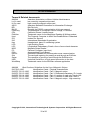
Interface
The communication parameters (port settings) are fixed for both USB & RS232 operation.
The parameters are:
Baud rate:
Data bits:
Parity:
Stop bit:
9600
8
None
1
RS-232:
A 6.0’ cable with DB-9 female connector with a 2.1 mm, center-positive power Jack
molded into the DB-9 housing. The following is signal pin-out of the connector:
DB-9F (RS-232) connector
PIN
Signal
1
Not Used
2
TXD
3
RXD
4
Not Used
5
Signal Ground
6
Not used
7
CTS
8
RTS
9
Not used
CASE
Chassis ground
POWER JACK
Center pin
Ring
+24VDC
Signal Ground
Direction
Out
In
In
Out
Connected to the die
cast cover
In
Table 1 RS-232 cable Pin-Outs
Copyright © 2010, International Technologies & Systems Corporation. All Rights Reserved
35 of 66
ID TECH EzWriter
USB-RS232:
The USB interface uses PC compatible communication drivers, which emulate an RS232
COM port operation through a USB serial connection. This approach allows the
application to use the more available USB connections through a virtual COM port.
A 6.0’ cable with a Serial A Plug and a 2.1 mm, center-positive power Jack molded into a
pigtail of the cable. The following is the signal pin-out of the connector:
USB connector
PIN
1
2
3
4
CASE
Signal
USB +5V
-Data
+Data
Ground
Chassis ground
Direction
In
In/out
In/out
-Connected to cover
POWER JACK
Center pin
Ring
+24VDC
Signal Ground1
In
--
Table 2 USB cable
1 - The power jack ground is connected to the USB connector ground.
Copyright © 2010, International Technologies & Systems Corporation. All Rights Reserved
36 of 66
ID TECH EzWriter
Command & Response Introduction
The ID TECH EzWriter is designed to industry norms. There are two command sets to
allow backward compatibility to past versions of hand swipe Reader/Writers. One
Command set is compatible with the model IDT-3840 Reader/Writer product and is
labeled as the IDT Command Set.
IDT Command Set
There is no protocol envelope. The commands are sent and responses received. The
Host software must deliberately take care with the timing and order of the communication
process.
This command set is the default set used for the Workshop utility. New features and
associated commands have been added to increase the utility & versatility of the product.
New commands added are:
Command to support BPI setting for each track
Command to support firmware upload from host interface
The EzWriter supports the following commands. The responses are provided.
Command: Reset Buffer
Command code: <ESC> a
Hex code: 1B 61
Response: none
Description: This command reset the EzWriter buffer to initial state. Encoding settings
are not affected by this command.
Command: Read
Command code: <ESC> r
Hex code: 1B 72
Response: [data block] <ESC> [status byte]
Description: This command requests the EzWriter to read a card swiped and respond with
the data read.
Command: Write
Command code: <ESC> w [data block]
Hex code: 1B 77 [data block]
Response: <ESC> [status byte]
Description: This command requests the EzWriter to write the data block into the card
swiped.
Copyright © 2010, International Technologies & Systems Corporation. All Rights Reserved
37 of 66
ID TECH EzWriter
Command: WRITE Passbook (supported in firmware v2.7 or later version)
Command code: <ESC> W [raw data block]
Hex code: 1B 57 [raw data block]
Response: <ESC> [status bytes]: status = 30 or 35 + 1B 3x
Description: This command processing is similar to raw data writing but responses are
different. If first write/verify passes, it responses 1B 30. If first write/verify fail, it
responses 1B 35, waiting for second swipe to verify; After second swipe, it send verify
result out as 1B 3x. x=0 for no error; x=1 for T1 error; x=2 for T2 error; x=3 for T1&T2
error; x=4 for T3 error; x=5 for T1 and T3 error; x=6 to T2 and T3 error; x=7 for T1, T2 and
T3 error.
Command: READ Passbook (supported in firmware v2.7 or later version)
Command code: <ESC> R <option>
Hex code: 1B 52 <option>
Response: [data block] <ESC> [status byte]
Description: This command requests the R/W to read a card swiped and respond with the
data read in ASCII format. It will read data in passbook format as well as ISO and AAMVA
format.
Status byte: 3x. x=0 for no error; x=1 for T1 error; x=2 for T2 error; x=3 for T1&T2 error;
x=4 for T3 error; x=5 for T1 and T3 error; x=6 to T2 and T3 error; x=7 for T1,T2 and T3
error.
<option> = ‘0’ – to send any decoded track data.
<option> = ‘1’ – to send only different track data.
Command: Communication test
Command code: <ESC> e
Hex code: 1B 65
Response: <ESC> y [1B] [79]
Description: This command is used to verify that the communication link between
computer and the EzWriter is up and good.
Command: All LED off
Command code: <ESC> <81>
Hex code: 1B 81
Response: none
Description: This command is used to turn off all the LEDs.
Command: All LED on
Command code: <ESC> <82>
Hex code: 1B 82
Response: none
Description: This command is used to turn on all the LEDs.
Command: Green LED on
Command code: <ESC> <83>
Copyright © 2010, International Technologies & Systems Corporation. All Rights Reserved
38 of 66
ID TECH EzWriter
Hex code: 1B 83
Response: none
Description: This command is used to turn on the Green LED.
Command: Yellow LED on
Command code: <ESC> <84>
Hex code: 1B 84
Response: none
Description: This command is used to turn on the Yellow LED.
Command: Red LED on
Command code: <ESC> <85>
Hex code: 1B 85
Response: none
Description: This command is used to turn on the Red LED.
Command: Sensor Test
Command code: <ESC> <86>
Hex code: 1B 86
Response: <ESC> 0 [1B] [30] if test ok
Description: This command is used to verify that the card sensing circuit of the EzWriter is
working properly. The EzWriter does not response until a card is sensed or the
Reader/Writer receives a RESET command.
Copyright © 2010, International Technologies & Systems Corporation. All Rights Reserved
39 of 66
ID TECH EzWriter
Command: Ram Test
Command code: <ESC> <87>
Hex code: 1B 87
Response: <ESC> 0 [1B] [30] ram test ok
<ESC> A [1B] [41] ram test fail
Description: This command is used to request The EzWriter to perform a test on its on
board RAM.
Command: Set Leading Zero
Command code: <ESC> z [leading zeros of 210 BPI Tracks][leading zeros of 75 BPI
tracks]
Hex code: 1B 7A [00~ff] [00~ff]
Response: <ESC> 0 [1B] [30] set ok:
<ESC> A [1B] [41] set fail
Description: This command sets the number of leading zeros written before the start
sentinel. The space should calculated as [leading zeros] X 25.4/ BPI (75or210) = mm
Default setting of leading zero = [3D][16]
TK1 & TK3 [3D] means leading zero=61 TK2 [16] means leading zero=22
Command: Check Leading Zero
Command code: <ESC> l
Hex code: 1B 6C
Response: 1B [00~ff] [00~ff]
Description: This command gets the current setting number of leading zeros. The first
byte is for 210 BPI track(s) and the second byte is for 75 BPI track(s).
Command: Erase Card
Command code: <ESC> c [select byte]
Hex code: 1B 63 [select byte]
Response: <ESC> 0 [1B] [30] command select byte ok
<ESC> 1 [1B] [31] erase error
<ESC> A [1B] [41] command select byte fail
Description: This command is used to erase the card data when card swipe.
*[select byte] format:
00000001: Track 1 only
00000010: Track 2 only
00000100: Track 3 only
00000011: Track 1 & 2
00000101: Track 1 & 3
00000110: Track 2 & 3
00000111: Track 1, 2 & 3
Copyright © 2010, International Technologies & Systems Corporation. All Rights Reserved
40 of 66
ID TECH EzWriter
Command: Select Track 2 BPI
Command code: <ESC> b [Density]
Hex code: 1B 62 [D2 or 4B]
Response: <ESC> 0 [1B] [30] select ok
<ESC> A [1B] [41] select fail
Description: This command is used to select the density of TK 2. [D2]: TK2 BPI=210 [4B]:
TK2 BPI=75
Command: Select Track 1 BPI
Command code: <ESC> f [Density]
Hex code: 1B 66 [D2 or 4B]
Response: <ESC> 0 [1B] [30] select ok
<ESC> A [1B] [41] select fail
Description: This command is used to select the density of TK 1. [D2]: TK1 BPI=210 [4B]:
TK1 BPI=75
Command: Select Track 3 BPI
Command code: <ESC> g [Density]
Hex code: 1B 67 [D2 or 4B]
Response: <ESC> 0 [1B] [30] select ok
<ESC> A [1B] [41] select fail
Description: This command is used to select the density of TK 3. [D2]: TK3 BPI=210 [4B]:
TK3 BPI=75
Command: Read Raw Data
Command code: <ESC> m
Hex code: 1B 6D
Response: [Raw Data Block] <ESC> [status byte]
Description: This command requests the EzWriter to read a card swipe but send without
ASCII decode. Refer to [Raw Data Block] & [Raw Data] Format.
Command: Write Raw Data
Command code: <ESC> n [Raw Data Block]
Hex code: 1B 6E [Raw Data Block]
Response: <ESC> [status byte]
Description: This command requests the EzWriter to write raw data block into the card
swiped. Refer to [Raw Data Block] & [Raw Data] format.
Command: Get Device Model
Command code: <ESC> t
Hex code: 1B 74
Response: <ESC> [Model] S
Description: This command used to get device model number compatible with IDT3840.
[Model] 1
Track 2
3
Track 1, 2, 3
5
Track 1, 2
Copyright © 2010, International Technologies & Systems Corporation. All Rights Reserved
41 of 66
ID TECH EzWriter
Command: Get Firmware Version
Command code: <ESC> u
Hex code: 1B 75
Response: <ESC> [version]
Description: This command can get the firmware version of the EzWriter
* [Version String] is an 8-byte version number with format: “ID TECH MagStripe
Reader/Writer V1.0”
Command: Get IDT3840 Compatible Firmware Version
Command code: <ESC> v
Hex code: 1B 76
Response: <ESC> [version]
Description: This command gets the original IDT3840 compatible firmware version.
* [Version String] is an 8-byte version number with format: “Rev.xx.xx”
Command: Set BPC
Command code: <ESC> o [tk1bit][tk2bit][tk3bit]
Hex code: 1B 6F [05-08][05-08][05-08]
Response: <ESC> 30 [tk1bit][tk2bit][tk3bit]
Description: This command is used to set the bit per character of every track.
Command: Set Hi-Co
Command code: <ESC> x
Hex code: 1B 78
Response: <ESC> 0
Description: This command is used to set the Reader/Writer status to write Hi-Co card
Command: Set Low-Co
Command code: <ESC> y
Hex code: 1B 79
Response: <ESC> 0
Description: This command is used to set EzWriter status to write Low-Co card
Command: Get Hi-Co or Low-Co Status
Command code: <ESC> d
Hex code: 1B 64
Response: <ESC> H – to write Hi-Co
<ESC> L – to write Low-Co
Description: This command is used to get the Reader/Writer write status
Command: Detecting EzWriter
Command code: 9
Hex code: 39
Response: <ESC> 4
Description: This command is used to detect if the EzWriter is existing or not
Copyright © 2010, International Technologies & Systems Corporation. All Rights Reserved
42 of 66
ID TECH EzWriter
Command: Shift to AMC protocol
Command code: <ESC> AMC
Hex code: 1B 41 4D 43
Response: <ESC> 0 :
Description: This command is used to shift the protocol to AMC and perform a reset in
AMC protocol.
Data Formats
[Data Block] format
Start Field
Commend
Code
Hex code
<ESC>s
EzWriter Data
Field
[Card data]
Ending Field
? <FS>
1B 73
[Card data]
3F 1C
[Card Data] format
Char Data
<ESC>1 [string1] <ESC>2 [string2] <ESC>3 [string3]
1B 01 [string1] 1B 02 [string2] 1B 03 [string3]
Char Code
Hex Code
[Status Byte] format
Status
Description
Ok
Read, Write, or Command ok
Read /
Track 1 error
Write
Track 2 error
Error
Track 1 and Track 2 error
Track 3 error
Track 1 and Track 3 error
Track 2 and Track 3 error
Track 1, Track 2 and Track 3 error
[Raw Data Block] format
Start Field
Command
Code
Hex code
Hex
30
31
32
33
34
35
36
37
<ESC>s
EzWriter Data
Field
[Raw Data]
?<FS>
1B 73
[Raw Data]
3F 1C
ASCII
0
1
2
3
4
5
6
7
Ending Field
[Raw Data] format
Char Code
Hex Code
Raw Data
<ESC>1[L1][string1] <ESC>2[L2][string2]
<ESC>3[L3][string3]
1B 01[L1][string1] 1B 02[L2][string2] 1B 03[L3][string3]
Note: [L1],[L2],[L3] is the length of [string1],[string2],[string3]
None available or none data on tracks does not output when swipe of card
Copyright © 2010, International Technologies & Systems Corporation. All Rights Reserved
43 of 66
ID TECH EzWriter
For example, when reading a card (encoded data on track 2 only) on dual track model,
data is transmitted like: 1B 73 1B 0100 1B 02 [L2] [string] 3F 1C
Initialization
HOST
Command code:
<ESC>a
HEX code: 1B, 61
Command code:
<ESC>e
HEX code: 1B, 65
Direction
EzWriter
(Reset)
(Serial port test)
Command test ACK:<ESC>y
HEX code: 1B, 79
(Reset)
Command code
<ESC>a
HEX code: 1B, 61
WRITE DATA Example
HOST
Command code:
<ESC>w<ESC>s<ESC>
01,01
<ESC> 02,23<ESC>
03,45?<FS>
HEX code:
1B, 77, 1B, 73, 1B, 01,
30, 31, 1B,
02, 32, 33, 1B, 03, 34,
35, 3F, 1C,
Direction
EzWriter
(write command)
(status ACK)
(Wait until swipe card)
Command ACK:<ESC>
<status>
HEX code: 1B, status,
Status= 30, No Error
Status= 31, Track 1 Write Error
Status= 32, Track 2 Write Error
Status= 33, Track 1, 2 Write Error
Status= 34, Track 3 Write Error
Status= 35, Track 1, 3 Write Error
Status= 36, Track 2, 3 Write Error
Status= 37, Track 1, 2, 3 Write Error
Status= 38, Read after write timeout
Copyright © 2010, International Technologies & Systems Corporation. All Rights Reserved
44 of 66
ID TECH EzWriter
READ DATA Example
HOST
Command
code:<ESC>r
HEX code: 1B, 72
Direction
(read command)
(status ACK)
Reader/Writer
(Wait until swipe card)
Command ACK:
<ESC>s<ESC> 01,%01?<ESC> 02,
23?<ESC> 03, 45??<FS><ESC>
<status>
HEX code:
1B, 73, 1B, 01, 25, 30, 31, 3F, 1B, 02,
3B, 32, 33, 3F, 1B, 03, 3B, 34, 35, 3F,
3F, 1C, 1B, status
Status= 30, No Error
Status= 31, Track 1 Read Error
Status= 32, Track 2 Read Error
Status= 33, Track 1, 2 Read Error
Status= 34, Track 3 Read Error
Status= 35, Track 1, 3 Read Error
Status= 36, Track 2, 3 Read Error
Status= 37, Track 1, 2, 3 Read Error
Status= 38, Read after write timeout
Copyright © 2010, International Technologies & Systems Corporation. All Rights Reserved
45 of 66
ID TECH EzWriter
AMC Compatible Command Set
This command set provides EzWriter compatibility for existing software applications and
product replacements. Workshop can operate with the AMC command set; however, this
command set has some limitations not found in the IDT command set. Using Workshop
with the IDT command set is recommended.
USI Protocols
The AMC USI protocol is used for information exchange. The user may select from 2
different variations for communicating with the unit.
USI0 (Protocol 0)
In USI0, all characters are transmitted and received using exactly the command
characters listed in the chapter on Commands and Responses found later in this manual.
There are no Headers, Trailers, or Block Check Characters. Protocol 0 presumes no
transmission errors. This is the default protocol after a reader reset, although the reader
may be configured to respond in USI0 or USI1 for the power-on message. This protocol
also enforces a five (5) second maximum timeout between characters.
USI1 (Protocol 1)
In USI1, all messages are preceded by the ASCII character STX, followed by the ASCII
character ETX with one Block Check Character (BCC). The BCC is an XOR of the data
bits of the entire message including the STX and ETX characters. (It does not include the
BCC itself.) The parity of the BCC is the selected parity, if any. This protocol also
enforces a 65ms maximum timeout between characters.
If the Interface detects an error in an incoming transmission, it responds with a
"Retransmit". If the host detects transmission error, it may, at its option request a
retransmission.
Protocol Selection
After a power-on or reset, the unit is initialized to use USI0. After the unit receives a valid
USI1 message from the host, it continues to operate in USI1 until it experiences a power
reset or receives a WARM RESET command.
Note: The UIC – AMC compatible reader/writer has EEPROM settings for Protocol 0
or Protocol 1 that breaks the AMC Protocol auto shift rule. EzWriter follows AMC
protocol auto shift rule as described above.
Flow Control
For both protocols, the host may at any time stop/start the unit transmission by using the
XOFF/XON commands. After a power-on or reset, the unit is initialized to XON
(communications enabled) mode.
EzWriter, in the AMC mode, must get commands from the host to operate the LEDs.
Workshop sends these commands to EzWriter to emulate the IDT protocol operation.
Copyright © 2010, International Technologies & Systems Corporation. All Rights Reserved
46 of 66
ID TECH EzWriter
AMC Commands and Responses
The following sections describe the commands that the host can send to the reader, this
is followed by a section describing the reader responses to the host. There are three
groups of commands, which can be sent to the reader. The first is used to manipulate the
reader (LED’s, status, etc.). The second is used to read and process magnetic stripe
data. The third group is used to write magnetic stripe data. Table 1, Table 3 and Table 4
summarize the commands of each group.
The unit executes commands received from the host one at a time and cannot execute a
new command until the previous command has been completed. Once the unit receives
a command, it performs the requested action and reports the results back to the host.
Unless otherwise specified, the examples shown assume that the unit uses the default
settings.
Reader Commands
Table 1 – USI Reader Command Summary
ASCII
HEX
Name
Use
<XON>
Length*
11
Resume transmission
Resume transmission to host
1
<XOFF>
13
Pause Transmission
Pause Transmission to host
1
%
25
Retransmit
Retransmits the last message again
1
9
39
Version Report
Transmits Version String
1
<ESC>
1B
Abort
Abort command
1
<DEL>
7F
Warm Reset
Simulates power cycle
1
#
23
Configuration Request
Sends Reader Configuration Byte
1
L
4C
Green LED ON
Turns on Green LED
1
l
6C
Green LED OFF
Turns off Green LED
1
M
4D
Red LED ON
Turns on Red LED
1
m
6D
Red LED OFF
Turns off Red LED
1
(
28
Green LED Flash
Start flashing Green LED
1
)
29
Red LED Flash
Start flashing Red LED
1
Y
59
Buzzer ON – Not support
Turns on Buzzer
1
y
79
Buzzer OFF – Not support
Turns off Buzzer
1
&
26
Card edge detect
K
4B
Yellow On – UIC command
Turns on both LEDs
1
k
6B
Yellow Off – UIC command
Turns off both LEDs
1
|
7C
Yellow Flash – UIC
command
Flashing both LEDs
1
1
*Length does not include protocol overhead characters, if any.
Copyright © 2010, International Technologies & Systems Corporation. All Rights Reserved
47 of 66
ID TECH EzWriter
<XON> (11H)
ACTION
Resume transmission of data by the unit.
<XOFF> (13H)
ACTION
%
Resume Reader Transmission
Pause Reader Transmission
Stops transmission of data by the unit.
(25H) Retransmit
ACTION
Retransmits the last message sent by the reader.
Use this command when you detect a communication error in a message received from
the reader. The reader re-transmits the last response it transmitted before this request.
The host may request retransmissions as many times as needed.
9
(39H) Version Report
ACTION
Transmit version information.
Send this when you want to know the version of the firmware currently loaded.
Example “ID TECH Reader/Writer Version 2.0 061001”
<ESC>
(1BH) Abort
ACTION
Abort current command and transmit an Acknowledge response (“^” 5EH) if
issued: After a single character “Load Encode Data” command (A, B, C) has been
responded to by the unit. After a double or triple character “Load Encode Data” command
(a3, E_, …) has been responded to by the unit. After the “Arm to Read” or “Encode data”
commands have been responded to by the unit. (The unit would be waiting for a card
swipe to read or encode.)
Note This command byte is not recognized as a command within data strings. It is
processed as a data character instead.
DEL
(7FH) Warm Reset
ACTION
Abort all current actions and cause the device to execute all initialization
functions. The unit responds exactly as it would for a “power up” cycle. It does not send
the typical acknowledge response (“^” 5EH). See section
Copyright © 2010, International Technologies & Systems Corporation. All Rights Reserved
48 of 66
ID TECH EzWriter
Reader Responses on page 60 for details. This is the command version of power cycling
the reader.
Note This command byte is not recognized as a command within data strings.
#
(23H) Configuration Request
Transmit a byte representing the configuration of the unit as follows:
ACTION
Table 2 –Configuration Byte
Bit Position*
0
1
2
3
4
5
6
7
Bit = 0
Bit = 1
Track 1 Read not present
Track 2 Read not present
Track 3 Read not present
not used – should be 0
Track 3 Write not present
Track 2 Write not present
Track 1 Write not present
parity bit**
Track 1 Read present
Track 2 Read present
Track 3 Read present
not used
Track 3 Write present
Track 2 Write present
Track 1 Write present
parity bit**
* bit 0 = lsb, bit 7 = msb
** is = 0 for units configured for 8 data bit transmission
Obtain details of the current unit configuration.
EXAMPLE The following byte (in hex) was returned: 63. It indicates a unit capable of
reading magnetic data on tracks 1 and 2; and writing magnetic data on to tracks 1 and 2.
&
(26H) Card Edge Detect
ACTION
The unit performs the following sequence: Transmit command
acknowledge (“^” 5EH). If not a reader/writer, then a Can’t Execute “~” reply is sent from
the unit. Wait for card swipe. Transmit Card Edge Acknowledge (“>” 3EH) after the unit
detects the card edge at the encode head. After a “Card Edge Detect”, command is
received and acknowledged. The only valid commands that are accepted for execution
are the “Abort” <ESC> and “Warm Reset” <DEL> commands. All other commands result
in an “Invalid Command” “!” response.
LED Commands. Use these commands to manipulate the reader’s LED.
L
l
M
m
(4CH)
(6CH)
(4DH)
(6DH)
Green LED ON
Green LED OFF
Red LED ON
Red LED OFF
Copyright © 2010, International Technologies & Systems Corporation. All Rights Reserved
49 of 66
ID TECH EzWriter
ACTION
The unit performs the following operations: Turn green/red LED colors ON
or OFF, as specified. Transmits an acknowledge response “^” (5EH). A bicolor LED is
used. If both red and green are ON, the LED appears amber/yellow.
(
)
(28H) Green LED flash
(29H) Red LED flash
ACTION
The unit performs the following operations: Begin flashing the specified LED
color ON and OFF. Transmits an acknowledge response “^” (5EH). The LED flashes
approximately .25 seconds ON and .25 seconds OFF. The flashing continues until
changed by another LED command. A single, bicolor LED is used on the unit. If both red
and green are turned ON, the LED appears amber/yellow.
Buzzer Commands. The reader hardware does not support a buzzer. This command is
here for reference only.
Y
y
(59H) Buzzer ON
(79H) Buzzer OFF
ACTION
The unit performs the following operations: Turn the unit’s buzzer ON or
OFF, as specified. Transmits an acknowledge response “^” (5EH).
Note The unit responds to these commands even though there is no buzzer installed.
Copyright © 2010, International Technologies & Systems Corporation. All Rights Reserved
50 of 66
ID TECH EzWriter
Magstripe Card Read Commands
Table 3 – Magstripe® Card Read Command Summary
ASCII
HEX
Name
Use
Length
*
P
50
Arm to Read
Clear buffers, wait for card read
1
p
70
51
R
52
S
53
q
71
r
72
s
73
I
49
Same as P but send “(“ at start of
Magstripe data and “)” at end. (Test Tool)
Process and send track 1 data after card
read using ISO track 1 decoding
Process and send track 2 data after card
read using ISO track 2 decoding
Process and send track 3 data after card
read using ISO track 3 decoding
Process and send track 1 data after card
read using selected ISO track decoding
Process and send track 2 data after card
read using selected ISO track decoding
Process and send track 3 data after card
read using selected ISO track decoding
Sends data after a data error is returned
1
Q
Arm to Read with speed
prompts
Transmit ISO standard
data, Track 1
Transmit ISO standard
data, Track 2
Transmit ISO standard
data, Track 3
Transmit ISO standard
data, Track 1
Transmit ISO standard
data, Track 2
Transmit ISO standard
data, Track 3
Transmit “Error Data”
U
55
Transmit custom data,
forward - Track 1
Sends data with/without nulls parsed using
specified bits per custom character
2,3
V
56
Transmit custom data,
forward - Track 2
Sends data with/without nulls parsed using
specified bits per custom character
2,3
W
57
Transmit custom data,
forward - Track 3
Sends data with/without nulls parsed using
specified bits per custom character
2,3
X
58
Process and send passbook data using
0CH or 0FH as the allowed End Sentinel
1
x
78
3F
Process and send passbook data using
the specified End Sentinel
Perform a Read-After-Write check on data
in the read buffers
2
?
Transmit Passbook
Data.
Not Support
Transmit Passbook Data
Not Support.
Write Verify
1
1
1
2
2
2
1
1
*Length does not include protocol overhead characters, if any.
Magstripe® Card Read Command Description
Copyright © 2010, International Technologies & Systems Corporation. All Rights Reserved
51 of 66
ID TECH EzWriter
P
(50H, uppercase) Arm to Read
ACTION
The unit performs the following sequence: Clear the read data buffers for all
tracks. Transmit command acknowledge (“^” 5EH). Wait for card swipe. Transmit read
acknowledge (“^” 5EH) after card swipe. After an “Arm to Read” command is received
and acknowledged. The only valid commands that are accepted for execution are:
“Abort” <ESC>, “Warm Reset” <DEL>, “Status” “$”, and LED control commands. All
other commands result in an “Invalid Command” “!” response.
p
(70H, lowercase)
Arm to Read with speed prompts
ACTION
The unit performs the following sequence: Clear the read data buffers for all
tracks. Transmit command acknowledge (“^” 5EH). Wait for card swipe. If Magstripe®
media is detected a “(" (28H) byte is sent, when media detect goes inactive a “)” (29H)
byte is sent. This is similar to the 'P' command, except an extra response '(' is reported
when a media is detected through the read head. A ')' response is reported when media
detect goes inactive. Mainly used as a tool for determining average swipe speed. Most
applications should not use this command. They should use the upper case P command
instead.
Q
R
S
(51H) Transmit ISO standard data, track 1
(52H) Transmit ISO standard data, track 2
(53H) Transmit ISO standard data, track 3
ACTION
The unit performs the following sequence: Process data in the read buffer
for the specified track according to ISO standard. If error is detected in card data,
transmit proper error response ('*' or '+'). Else, transmit data in ASCII.
Note Q, R, and S are special single byte commands for the corresponding cases of
double byte commands, e.g. Q has the same effect as q1.
q
r
s
(71H) Transmit track 1 data
(72H) Transmit track 2 data
(73H) Transmit track 3 data
FORMAT
2-byte command - Command character (q, r, s) is followed by an ASCII
number (1, 2 or 3) representing the ISO track format for processing the Magstripe data.
ACTION
The unit performs the following sequence: Process data in the read buffer
for the specified track and format. If no card data errors, transmit data in ASCII.
If error is detected in card data, transmit proper error response ('*' or '+'). These
commands allow a track to be transmitted with a different track’s ISO format. For
example to transmit track 1's data using ISO track 2 format send “q2” (71H, 32H). The
uppercase equivalents (Q, R, and S) are equivalent to q1, r2, and s3.
Note The s1 command decodes track 3 using AAMVA format if the unit is configured for
ISO and AAMVA decoding.
Copyright © 2010, International Technologies & Systems Corporation. All Rights Reserved
52 of 66
ID TECH EzWriter
I
(49H) Transmit “Error Data”
ACTION
The unit performs the following sequence:
If the previous read command resulted in an error (response was '*', e.g. no end sentinel,
parity or LRC error), transmit the data regardless of the error(s). If there was no error,
transmit '+'. The “I” command allows you to recover data even if the reader detects data
errors. This command does not work for a no start sentinel '+' response.
U
V
W
(55H) Transmit Custom Data, forward swipe, track 1
(56H) Transmit Custom Data, forward swipe, track 2
(57H) Transmit Custom Data, forward swipe, track 3
FORMAT
These commands may be either 2 or 3 bytes long.
2-byte command – Used to request custom data with no internal null characters allowed.
The command character is followed by an ASCII number (3,4,5,6 or 7) which specifies the
number of bits per custom character.
3-byte command – Used to request custom data with internal null characters. The
command character is followed by the underline character (5FH) and the ASCII number
(3,4,5,6 or 7) which specifies the number of bits per custom character.
ACTION
The unit performs the following sequence: Process data in read buffer for
the specified track, based upon the “number of bits” character. Transmits data formatted
one byte per character with the unused most significant bits in each byte set to '0'.
Note Use the appropriate 2 or 3 byte form depending on the presence or absence of null
(00H) characters. Data is returned in the low order bits for 3,4,5,6, or 7 bits per character.
?
(3FH) Write verify
ACTION
The unit performs the following sequence: Check that valid write data exists
in Encode Data storage buffer. Send “*” error if not. Else, Clear the read data buffers for
all tracks; Transmit command acknowledge (“^” 5EH); Wait for card swipe; Transmit
acknowledge (“^” 5EH) after card swipe if card passes the Read After Write checks on all
tracks that were previously encoded; Otherwise, send the proper RAW (1, 2 and/or 3)
error response in ASCII. After a “Write Verify” command is received and acknowledged
the only valid commands that are accepted for execution are: “Abort” <ESC> and “Warm
Reset” <DEL> commands. All other commands result in an “Invalid Command” “!”
response.
Copyright © 2010, International Technologies & Systems Corporation. All Rights Reserved
53 of 66
ID TECH EzWriter
Magstripe Card Write Commands
Table 4 – MagStripe Card Write Command Summary
ASCII
HEX
Name
Use
A
41
Load ISO Standard Data
for writing Track 1
Load ISO Standard Data
for writing Track 2
Load ISO Standard Data
for writing Track 3
Load ISO Data for writing
Track 1
Load ISO Data for writing
Track 2
Load ISO Data for writing
Track 3
Load passbook data for
writing tracks 2 and 3.
Not support
Load Custom Data for
Writing Track 1
Load Custom Data for
Writing Track 2
Load Custom Data for
Writing Track 3
Set Write Density (for
individual tracks)
Set Write density to 210
bpi on Tracks 1 and 3
Set Write density to 75
bpi on Tracks 1 and 3
Set Write density to 210
bpi on Track 2
Set Write density to 75
bpi on Track 2
Set Default Write Current
B
42
C
43
a
61
b
62
c
63
j
6A
E
45
F
46
G
47
;
3B
O
4F
o
6F
N
4E
n
6E
[
5B
]
5D
<
3C
>
3E
@
40
View Default Write
Current
Set Temporary Write
Current
View Temporary Write
Current
Arm to Write with RAW
Z
5A
Arm to Write, no RAW
z
7A
Arm to Write with RAW
and speed prompts
Length
*
To encode cards with standard ISO
format
To encode cards with standard ISO
format
To encode cards with standard ISO
format
Allows for ISO track formats in nonstandard track assignments
Allows for ISO track formats in nonstandard track assignments
Allows for ISO track formats in nonstandard track assignments
To encode passbooks with the IBMPassbook format.
1
To encode cards using a user defined
data format
To encode cards using a user defined
data format
To encode cards using a user defined
data format
Change the density of data that is written
to the card for the specified track.
Returns tracks 1 & 3 encoding density
settings to ISO standard for those tracks.
Change encoding density on tracks 1 & 3
2 or 3
1
Change encoding density on track 2
1
Returns track 2 encoding density setting
to ISO standard for track 2.
Change default write current setting in
EEPROM.
View default write current setting in
EEPROM.
Change setting of write current used to
encode cards.
Check setting of write current used to
encode cards.
Encode cards and perform Read After
Write (RAW) verification.
Required for encoding Extended length
media on VC units.
Same as @ but send “(“ at start of write
and “)” at end of read. (Test tool)
1
1
1
2
2
2
2
2 or 3
2 or 3
3
1
4
1
4
1
1
1
1
*Length does not include protocol overhead characters, if any.
Copyright © 2010, International Technologies & Systems Corporation. All Rights Reserved
54 of 66
ID TECH EzWriter
Load Data Commands Use these commands to load data into the unit‘s encode storage.
A
B
C
(41H) Load ANSI/ISO standard data for encoding track 1
(42H) Load ANSI/ISO standard data for encoding track 2
(43H) Load ANSI/ISO standard data for encoding track 3
ACTION
The unit performs the following sequence: Clear the Encode Data storage
for the specified track. Transmit Command acknowledge (“^” 5EH). Wait for download of
the encode data in ASCII, terminated by the ASCII EOT character (04H). If data is good,
transmit acknowledge (“^” 5EH). Else, transmit “*” error response. Note Commands A,
B and C are special cases of the two byte commands a, b, and c. Example: A = a1, B =
b2, and C = c3.
a
b
c
(61H) Load ISO data for encoding track 1
(62H) Load ISO data for encoding track 2
(63H) Load ISO data for encoding track 3
FORMAT
2-byte command – Command character (a, b, c) is followed by an ASCII
number (1, 2 or 3) representing the ISO track format for processing the Magstripe data.
ACTION
The unit performs the following sequence: Clear the Encode Data storage
for the specified track. Transmit Command acknowledge (“^” 5EH). Wait for download of
the encode data in ASCII, terminated by the ASCII EOT character (04H).
If data is good, transmit acknowledge (“^” 5EH). Else, transmit “*” error response
j
(6AH) Load Passbook data for encoding track 2/3
FORMAT
2-byte command – The command character (j), is followed by an ASCII
character representing the end sentinel used for IBM-Passbook encoding. Only the lower
four bits of the ASCII character are used for the end sentinel. If the <ESC> character is
sent for the end sentinel, then the command is aborted and the unit sends acknowledge
(“^” 5EH).
ACTION
The unit performs the following sequence: Clear the Encode Data storage
for tracks 2 and 3. Transmit Command acknowledge (“^” 5EH). Wait for download of the
encode data in ASCII, terminated by the ASCII EOT character (04H).
If data is good, transmit acknowledge (“^” 5EH). Else, transmit “*” error response
Note (1) Use this command when you only want to write passbook formatted data to a
card. Two redundant data fields are encoded on tracks 2 and 3.
(2) Tracks 2 and 3 write data buffers are loaded with the passbook formatted data.
(3) The encoding density for tracks 2 and 3 are always set to 210 bpi when this command
is used and completed.
(4) After this command is completed, arming the unit to write always writes over tracks 2
and 3.
(5) Command is only supported on reader/writer units with tracks 2 and 3.
Reader/Writers that have track 1 and 2 only respond with a Can’t Execute (“~” 7EH).
Copyright © 2010, International Technologies & Systems Corporation. All Rights Reserved
55 of 66
ID TECH EzWriter
E
F
G
(45H) Load Custom data for encoding track 1
(46H) Load Custom data for encoding track 2
(47H) Load Custom data for encoding track 3
FORMAT
These commands may be either 2 or 3 bytes long.
2 byte command – Used to load custom data with no internal null characters allowed. The
command character is followed by an ASCII number (3,4,5,6 or 7) which specifies the
number of bits per custom character.
3 byte command – Used to load custom data with internal null characters. The command
character is followed by the underline character (“_” 5FH) and the ASCII number (3,4,5,6
or 7) which specifies the number of bits per custom character.
ACTION
The unit performs the following sequence: Clear the Encode Data storage
for the specified track. If an invalid track number is sent the unit sends an Invalid
Command (“!” 21H) response. Transmit Command acknowledge (“^” 5EH)
Wait for download of the Encode Data string in ASCII, terminated by the ASCII EOT
character (04H). If data is good, transmit Acknowledge (“^” 5EH). Else, transmit “*” error
response.
Density Commands: Use these commands to set the bit density of the encoded data
;
(3BH) Set Write Density
FORMAT
3-byte command - “;TD” where:
; = Command character (3BH)
T = ASCII character (1, 2 or 3) representing the track number being configured.
D = ASCII character (H or h) for 210bpi; ASCII character (L or l) for 75bpi
ACTION
The unit performs the following sequence: Set density for the specified
track. If an invalid track number or density parameter is sent the unit sends a “*” reply.
Transmit Command acknowledge (“^” 5EH). This command allows for full independence
in setting the densities for each track. Tracks 1 and 3 are not forced to be the same as in
previous models.
Notes (1) On Power-up/Reset, Tracks 1 and 3 default to 210bpi and Track 2 to 75bpi.
(2) These commands must be sent prior to any Load Data commands. Errors may occur
otherwise.
Copyright © 2010, International Technologies & Systems Corporation. All Rights Reserved
56 of 66
ID TECH EzWriter
O
o
N
n
(4FH)
(6FH)
(4EH)
(6EH)
Set Write Density to 210bpi on tracks 1 and 3
Set Write Density to 75bpi on tracks 1 and 3
Set Write Density to 210bpi on track 2
Set Write Density to 75bpi on track 2
ACTION
The unit performs the following sequence: Set density for the specified
track(s). Transmit Command acknowledge (“^” 5EH). These commands were retained to
preserve compatibility with the older AMC 712 command set. If track 1 and 3 require
different density settings, use the more general Set Write Density (“;” 3BH) command.
Note (1) On Power-up/Reset, Tracks 1 and 3 default to 210bpi and Track 2 to 75bpi.
(2) These commands must be sent prior to any Load Data commands. Errors may occur
otherwise.
Write Current Commands: Use these commands to set and review the write current
used to encode data on to cards. (VC units only)
[
(5BH) Set Default Write Current
FORMAT
4-byte command – Command character ([), is followed by three ASCII
number characters (0 thru 9) representing the write current used for encoding.
ACTION
The unit performs the following sequence: Change the write current setting
in EEPROM and RAM to the specified value. Valid values are 000 to 255 only. Any other
values outside this range gets a “*” reply from the unit. If not a VC unit, then a “~” reply is
sent from the unit. Transmit Command acknowledge (“^” 5EH). This command may be
sent anytime prior to an “Arm to Write” command.
Notes (1)
In USI0 there is a 5-second inter-character timeout
On Power-up/Reset, this value is used for encoding cards.
The previous default current value is lost.
Recommended values:
Typical low coercivity (~300 Oersted) setting = 036
Typical high coercivity (4140 Oersted) setting = 255
]
(5DH) Review Default Write Current
ACTION
The unit returns a 3 ASCII character response representing the default write
current setting stored in EEPROM, MSD first. If not a VC unit, then a “~” reply is sent
from the unit.
Note The value returned is not necessarily the value used to presently encode cards
with; i.e. the temporary value could be different.
Copyright © 2010, International Technologies & Systems Corporation. All Rights Reserved
57 of 66
ID TECH EzWriter
<
(3CH) Set Temporary Write Current
FORMAT
4-byte command – Command character ([), is followed by three ASCII
number characters (0 thru 9) representing the write current used for encoding.
ACTION
The unit performs the following sequence: Change the write current setting
RAM to the specified value. Valid values are 000 to 255 only. Any other values outside
this range gets a “*” reply from the unit. If not a VC unit, then a “~” reply is sent from the
unit. Transmit Command acknowledge (“^” 5EH). This command may be sent anytime
prior to an “Arm to Write” command.
Notes In USI0 there is a 5-second inter-character timeout
On Power-up/Reset the unit sets the write current to the default value read from the onboard EEPROM. The temporary value is lost.
Recommended values:
Typical low coercivity (~300 Oersted) setting = 036
Typical high coercivity (4140 Oersted) setting = 255
This is an AMC compatible command. EzWriter only supports either low or high
coercivity, all settings above 170 is high coercivity; otherwise, EzWriter is set to
low coercivity operation.
>
(3EH) Review Temporary Write Current
ACTION
The unit returns a 3 ASCII character response representing the temporary
write current setting stored in RAM, MSD first. If not a VC unit, then a “~” reply is sent
from the unit.
Note The value returned is the value presently used to encode cards with. This value
could be different from the default write current value stored in EEPROM.
Arm to Write Commands: Use these commands to write cards.
ASCII Char Definition of Instruction
@
(40H) Arm to Write with RAW verification
ACTION
The unit performs the following sequence: Check that valid write data exists
in Encode Data storage buffer. Send “*” error if not. Else, Clear read buffers; Transmit
Command acknowledge (“^” 5EH); Wait for card swipe. Transmit acknowledge (“^” 5EH)
after card swipe if card passes the Read After Write checks on all tracks that were
encoded. Otherwise send the proper RAW (1, 2 and/or 3) error response. After a “Arm to
Write” command is received and acknowledged the only valid commands that are
accepted for execution are: “Abort” <ESC> and “Warm Reset” <DEL> commands. All
other commands result in an “Invalid Command” “!” response.
Copyright © 2010, International Technologies & Systems Corporation. All Rights Reserved
58 of 66
ID TECH EzWriter
Z
(5AH) Arm to Write, no RAW verification
ACTION
The unit performs the following sequence: Check that valid write data exists
in Encode Data storage buffer. Send “*” error if not. Else, Clear read buffers; Transmit
Command acknowledge (“^” 5EH); Wait for card swipe. Transmit acknowledge (“^” 5EH)
after card swipe. After a “Arm to Write” command is received and acknowledged the only
valid commands that are accepted for execution are: “Abort” <ESC> and “Warm Reset”
<DEL> commands. All other commands result in an “Invalid Command” “!” response.
z
(7AH) Arm to Write, with RAW and speed prompts
ACTION
The unit performs the following sequence: Check that valid write data exists
in Encode Data storage buffer. Send “*” error if not. Else, Clear read buffers; Transmit
Command acknowledge (“^” 5EH); Wait for card swipe. A “(" (28H) byte is sent when the
media is first detected at the write head. After the card passes the read head and the
media detect goes inactive, a “)” (29H) byte is sent if the card passes the Read After
Write checks on all tracks that were encoded. Transmit acknowledge (“^” 5EH) after card
swipe.
After a “Arm to Write” command is received and acknowledged the only valid commands
that are accepted for execution are “Abort” <ESC> and “Warm Reset” <DEL>
commands. All other commands result in an “Invalid Command” “!” response.
This is similar to the '@' command, except an extra response '(' is reported when a media
is detected at the write head. A ')' response is reported when media detect goes inactive.
Mainly used as a tool for determining average swipe speed. Most applications should not
use this command. They should use the ‘@’ command instead.
Copyright © 2010, International Technologies & Systems Corporation. All Rights Reserved
59 of 66
ID TECH EzWriter
Reader Responses
There are two types of responses that the unit, solicited and unsolicited. The unit
produces a solicited response after receiving a command from the host. This includes
command acknowledgements, card data, etc. The unit produces an unsolicited response
normally due to a user’s action or a power on situation.
Solicited Responses
Table 5 – Solicited Response Summary
ASCII
HEX
Name
^
5E
21
2A
2B
2D
2F
3F
7E
Command Completed (ACK)
Invalid Command
Error
No data found
Insufficient leading zeros for custom writing
lsb of first character not a “1” for custom writing
Communications error
Can’t Execute, hardware does not support command
!
*
+
/
?
~
Use
Length*
1
1
1
1
1
1
1
1
*Length does not include protocol overhead characters, if any.
Unsolicited Responses
Table 6 – Unsolicited Response Summary
ASCII
:
^
1
2
3
(
)
>
HEX
3A
5E
31
32
33
28
29
3E
Name
Use
Power On Report
Card swipe occurred when armed to read or write
Unsuccessful read after write – Track 1
Unsuccessful read after write – Track 2
Unsuccessful read after write – Track 3
Card speed measurement - start
Card speed measurement - end
Card edge detected
Length*
1
1
1,2 or 3**
1,2 or 3**
1,2 or 3**
1
1
1
*Length does not include protocol overhead characters, if any.
** Responses combined into one message back to the host.
Copyright © 2010, International Technologies & Systems Corporation. All Rights Reserved
60 of 66
ID TECH EzWriter
References for AMC protocol design
1. “MSR206-7HL Magnetic Stripe Card Reader/Writer (High & Low Coercivity)
Programmer’s Manual Revision C - 26 Dec. 2003” ; From UIC
2. “Model 722VC/722LC Magstripe Swipe Reader/Writer Intelligent Series USER GUIDE
& SPECIFICATIONS; Revision 50”; From AMC
3. “Writing raw data to magnetic card” (MSR206_7HL-Writing raw data to magnetic
card1A.doc) – From UIC;
Difference between AMC R/W and EzWriter
Functions not supported:
1. EzWriter does not support variable coercivity settings. Commands are compatible but
functionally EzWriter treats coercivity settings above 1270 as Hi-Co & others as Low-Co.
2. EzWriter does not support Buzzer function
Extra Commands:
‘K’ – Yellow LED on (To be compatible with UIC MSR206-HL)
‘k’ – Yellow LED off (To be compatible with UIC MSR206-HL)
‘l’ – Yellow LED flash (To be compatible with UIC MSR206-HL)
‘9’ To detect EzWriter under IDT protocol or to get version string in AMC protocol
Switching Between Protocols:
‘ToIDT’ – Shift back to IDT (UIC) protocol
‘\1BToAMC’ – Shift to AMC protocol
Special AMC Emulation Settings
EzWriter Special Settings for special applications
(March 1, 2007)
The following special setting commands are added to EzWriter to support applications
that may need the un-documented operation in AMC Protocol.
(Applies to EzWriter firmware V2.2X and later)
There are four commands. Two commands are used to enter & exit the Special Setting
mode for the Setting Commands and two are used to perform the settings.
Setting Method:
Any RS232 communication utility program with 9600,7,O,1 settings should work.
EzWriter must be in AMC mode for settings. (Workshop can be used to change EzWriter
into the AMC mode). (Reference, the EzWriter default settings are: 9600,8,N,1).
Copyright © 2010, International Technologies & Systems Corporation. All Rights Reserved
61 of 66
ID TECH EzWriter
The IDT internal engineering program MSRW-7-O.exe program can be used to perform
the settings.
1. Launch MSRW-7-O.exe program
2. Click “Port” and select proper port to open
3. Select “Keyboard” on the upper-writer corner from the program window.
4. Type in each command followed by “Enter” key.
Enter setting mode
Command: \09\09\09
Reader Response: ^^!
Set to “Don’t Send ‘+’ ”
// Note: A1D00 will send ‘+’
Command: A1D5A
Reader Response: ^^^
Set to “Single Byte Write Error Report”
// Note: A1E00 will send multiple error
report when
// multiple tracks failed
Command: A1E5A
Reader Response: ^^^
Save setting
Command: @
Reader Response: ^:
Reasons for using these settings:
1. The AMC Reader/Writer has a “conditional bug” – Sometimes it does not response to
read command “Q”, “R”, “S”. According to specification, the R/W should always have a
response, either normal data or ‘*’ for error data and ‘+’ for no data. Some programs
function only with no response when there is no data in the track. A normal no data
response ‘+’ from EzWriter will cause the program to fail and require the PC to be
rebooted to recover.
2. The some programs do not handle multiple track writing error situations according to
specification and send commands before the R/W is finish sending the writing error
responses ‘1’, ‘2’ and ‘3’. It then works “properly’ with messed up responses from AMC
R/W. Program parameters: Com1wr xx 16 1 1 1001, where xx corresponds to one data
file.
3. The EzWriter will not write a “No Data” track. The definition of a “No Data” track is an
attempt to write a start sentinel character, and end sentinel character, the LRC, and there
are no data characters. There must be at least one data character; otherwise, the
EzWriter leaves the track “empty” (no writing at all).
Copyright © 2010, International Technologies & Systems Corporation. All Rights Reserved
62 of 66
ID TECH EzWriter
Maintenance
The EzWriter requires cleaning of the card slot on a regular interval. The interval is
approximate and should be after every 50,000 card swipes. Regular cleaning insures oils
and debris do not accumulate on the operating components.
Over time, operation can cause a film to collect on the heads and other surfaces. This
film should be removed using “cleaning cards”. These are available from magnetic stripe
cleaning card sources. Cleaning cards are about the same size as an ID1 (credit card)
and have an absorbent surface on one or both sides. The absorbent surface has an
alcohol solvent that should remove any film. The absorbent surface should be damp; the
surface should not be saturated.
Swipe the card five to ten times with the solvent side of the card toward the read and write
heads and then again five to ten times with the solvent side opposite the heads.
The cleaning cards may not remove all the debris. In the case of debris such as dust and
card particles in the slot, use an aerosol can product containing clean compressed air.
The clean air can be used to blow debris from the slot. Direct the stream of air at a low
angle into the slot and run the nozzle along the slot. Direct the air in the direction of the
card travel and then in the opposite direction. Inspect the slot by looking down its length
with a good backlight to see if all debris is removed.
The metal housing can be cleaned with a mild detergent applied to a soft cloth that is rung
almost dry. Detergent should not be allowed to enter the card slot.
Warning: There are no serviceable components inside the EzWriter. Opening the
Reader/Writer voids the warranty. Tampering with the write head or tachometer
assemblies may change the EzWriter calibration for ISO standards operation.
Copyright © 2010, International Technologies & Systems Corporation. All Rights Reserved
63 of 66
ID TECH EzWriter
Appendix A Outline drawings
Copyright © 2010, International Technologies & Systems Corporation. All Rights Reserved
64 of 66
ID TECH EzWriter
Appendix B: Card Formats
ISO
Table 7 – ISO Card Format
Trac
k
Densit
y (bpi)
Total
Characters
**
79
Character Set
Start
Sentinel
End
Sentinel
210
Bits/
Char
*
7
Alphanumeric
%
?
Field
Separat
or
^
1
2
75
5
40
Numeric only
;
?
=
3
210
5
107
Numeric only
;
?
=
* Includes ODD parity bit
** Includes Start Sentinel, End Sentinel, and LRC characters
Track 1 allowed characters
Table 1 – Alphanumeric Character Set
b6
b5
b4
b3
b2
b1
COL
ROW
0
0
0
0
0
0
0
0
1
1
1
1
1
1
1
1
0
0
0
0
1
1
1
1
0
0
0
0
1
1
1
1
0
0
1
1
0
0
1
1
0
0
1
1
0
0
1
1
0
1
0
1
0
1
0
1
0
1
0
1
0
1
0
1
0
1
2
3
4
5
6
7
8
9
10
11
12
13
14
15
0
0
0
0
1
1
1
0
2
1
1
3
SP
! (1)
“ (1)
# (2)
$
% (3)
& (1)
/ (1)
(
)
* (1)
+ (1)
, (1)
.
/
0
1
2
3
4
5
6
7
8
9
@ (1)
A
B
C
D
E
F
G
H
I
J
K
L
M
N
O
P
Q
R
S
T
U
V
W
X
Y
Z
[(4)
\ (4)
](4)
^(3)
DEL (1)
: (1)
; (1)
< (1)
= (1)
> (1)
? (3)
(1) These characters are for hardware control purposes only.
(2) This character is reserved for optional additional graphic symbols.
(3) These characters have the following meanings: Position 0/5 % Represents “start sentinel”
1/15 ? Represents “end sentinel”
3/14 ^ Represents “field separator”
(4) These characters are reserved for additional national characters when required. They are not to be
used internationally.
Copyright © 2010, International Technologies & Systems Corporation. All Rights Reserved
65 of 66
ID TECH EzWriter
Track 2 and 3 allowed characters
Table 2 – Numeric Character Set
P
1
0
0
1
0
1
1
0
0
1
1
0
1
0
0
1
(1)
(2)
(3)
(4)
b4
0
0
0
0
0
0
0
0
1
1
1
1
1
1
1
1
Bits
b3
0
0
0
0
1
1
1
1
0
0
0
0
1
1
1
1
b2
0
0
1
1
0
0
1
1
0
0
1
1
0
0
1
1
b1
0
1
0
1
0
1
0
1
0
1
0
1
0
1
0
1
Row
0
1
2
3
4
5
6
7
8
9
10
11
12
13
14
15
Character
0
1
2
3
4
5
6
7
8
9
: (1)
; (2)
< (1)
= (3)
> (1)
? (4)
These characters are for hardware control purposes only.
Start sentinel
Field separator
End sentinel
AAMVA
Table 8 – AAMVA Card Format
Track
Density
(bpi)
Bits/
Char*
Character Set
Start
Sentinel
End
Sentinel
Field
Separator
7
Total
Characters
**
82
1
210
Alphanumeric
%
?
^
2
75
5
40
Numeric only
;
?
=
3
210
7
82
Alphanumeric
%
?
^
* Includes ODD parity bit
** Includes Start Sentinel, End Sentinel, and LRC characters
Copyright © 2010, International Technologies & Systems Corporation. All Rights Reserved
66 of 66