1
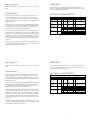
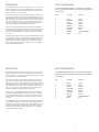
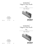
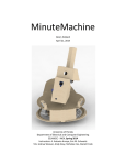
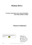
TM
MINIMAG
Magnetic Stripe Reader
TTL
User’s Manual
ID TECH
10721 Walker Street
Cypress, California 90630
(714) 761-6368
www.id-tech.net
80030501-005
Rev. A R02/05
#422
TM
MINIMAG
Magnetic Stripe Reader
TTL
User’s Manual
ID TECH
10721 Walker Street
Cypress, California 90630
(714) 761-6368
www.id-tech.net
80030501-005
Rev. A R02/05
#422
Agency Approved
OPERATION
Specifications for subpart B of part 15 of FCC rule for a Class A computing
device.
Make sure the reader is properly cabled and is receiving sufficient power. To
read a card, slide the card, in either direction, through the reader slot, with the
magnetic stripe facing the magnetic head.
Limited Warranty
ID TECH warrants this product to be in good working order for a period of
one year from the date of purchase. If this product is not in good working
order as warranted above, or should this product fail to be in good working
order at any time during the warranty period, repair or replacement shall be
provided by ID TECH.
This warranty does not cover incidental or consequential damages incurred
by consumer misuse, or modification of said product. For limited warranty
service during the warranty period, please contact ID TECH to obtain an
RMA number and instructions for returning the product.
©2005 International Technologies & Systems Corporation. The information
contained herein is provided to the user as a convenience. While every effort
has been made to ensure accuracy, ID TECH is not responsible for damages
that might occur because of errors or omissions, including any loss of profit
or other commercial damage. The specifications described herein were current at the time of publication, but are subject to change at any time without
prior notice.
ELECTRICAL CHARACTERISTICS
DC Electrical Characteristics (25° C)
Item
Symbol
Min.
Supply Voltage
VCC
2.6
Maximum
Active Supply
Typical
ICC
Maximum
Minimum High
Level Voltage
Maximum Low
Level Voltage
Unit
V
1.1 per track
mA
+ IMDL
Current
Sleep Current
Maximum
5.5
Condition
IMDL=(VCC - VOL)/10K
30 per track
ISLEEP
VCC-0.03
VOH
VOL
+ IMDH
µA
V
2.3
V
5.25
V
0.1
V
0.22
V
0.2
V
IMDH=(VCC - VOH)/10K
IOUT=50µA
IOUT=3mA, VCC=2.6V
IOUT=6mA, VCC=5.5V
IOUT=50µA
IOUT=3mA, VCC=2.6V
IOUT=6mA, VCC=5.5V
ID TECH is a registered trademark of International Technologies & Systems
Corporation. MiniMag and Value through Innovation are trademarks of International Technologies & Systems Corporation.
1
6
Agency Approved
OPERATION
Specifications for subpart B of part 15 of FCC rule for a Class A computing
device.
Make sure the reader is properly cabled and is receiving sufficient power. To
read a card, slide the card, in either direction, through the reader slot, with the
magnetic stripe facing the magnetic head.
Limited Warranty
ID TECH warrants this product to be in good working order for a period of
one year from the date of purchase. If this product is not in good working
order as warranted above, or should this product fail to be in good working
order at any time during the warranty period, repair or replacement shall be
provided by ID TECH.
This warranty does not cover incidental or consequential damages incurred
by consumer misuse, or modification of said product. For limited warranty
service during the warranty period, please contact ID TECH to obtain an
RMA number and instructions for returning the product.
©2005 International Technologies & Systems Corporation. The information
contained herein is provided to the user as a convenience. While every effort
has been made to ensure accuracy, ID TECH is not responsible for damages
that might occur because of errors or omissions, including any loss of profit
or other commercial damage. The specifications described herein were current at the time of publication, but are subject to change at any time without
prior notice.
ELECTRICAL CHARACTERISTICS
DC Electrical Characteristics (25° C)
Item
Symbol
Min.
Supply Voltage
VCC
2.6
Maximum
Active Supply
Typical
ICC
Maximum
Minimum High
Level Voltage
Maximum Low
Level Voltage
Unit
V
1.1 per track
mA
+ IMDL
Current
Sleep Current
Maximum
5.5
IMDL=(VCC - VOL)/10K
30 per track
ISLEEP
VOH
VOL
VCC-0.03
+ IMDH
µA
V
2.3
V
5.25
V
0.1
V
0.22
V
0.2
V
ID TECH is a registered trademark of International Technologies & Systems
Corporation. MiniMag and Value through Innovation are trademarks of International Technologies & Systems Corporation.
1
Condition
6
IMDH=(VCC - VOH)/10K
IOUT=50µA
IOUT=3mA, VCC=2.6V
IOUT=6mA, VCC=5.5V
IOUT=50µA
IOUT=3mA, VCC=2.6V
IOUT=6mA, VCC=5.5V
DATA, CLOCK AND CARD PRESENT SIGNALS
The following is a timing diagram of typical DATA and CLOCK signals from
ID TECH electronics:
CLOCK: The CLOCK output is narrow pulse normally high, and goes low
when data is valid. The data level is stable at both the rising and falling edges
of the CLOCK pulse. CLOCK pulse width is typically 32 microseconds.
CARD PRESENT: The CARD PRESENT signal indicates data is being read
from the media being passed through the slot. It will not switch until flux
reversals (magnetic pulses) have been detected. After the flux reversals have
been detected, CARD PRESENT goes low. It stays low throughout the reading process and for 5 to 10 milliseconds, after the last flux reversal is read.
Typically, CARD PRESENT is used to signal the start and finish of a card
read. It may also be used as an interrupt signal for alerting the firmware that
the reading operation is in process.
DATA: The DATA output level indicates the value of the bit being decoded
during a CLOCK pulse. It is a low level for ones (1) and a high level for
zeros (0). The DATA signal’s level is steady at the rising and falling edges
and during the low level of the CLOCK pulse.
SPECIFICATIONS
Operating
Temperature:
32° F to 131° F (0° C to 55° C).
Storage
Temperature:
-22° F to 158° F (-30° C to 70° C).
Humidity:
Maximum 95% non-condensing.
MTBF:
Read electronics, 21,000,000 POH.
Magnetic
Head Life:
1,000,000 passes minimum.
Rail and
Cover Life:
1,000,000 passes minimum.
Read Rate:
Less than one error in 100,000 bits on
cards conforming to ISO7811 1-5 (not
induced by operator error).
Swipe Speed:
3 to 60 inches per second, bi-directional.
Card Thickness:
.01 to .045 inches.
Slot Width:
.050 inches (1.37mm).
Dimensions:
Length: 3.54 inches (90mm).
Width: 1.34 inches (34mm).
Height: 1.10 inches (28mm).
Weight:
4.6 oz.
Cable Length:
6-foot straight cable.
5
DATA, CLOCK AND CARD PRESENT SIGNALS
The following is a timing diagram of typical DATA and CLOCK signals from
ID TECH electronics:
CLOCK: The CLOCK output is narrow pulse normally high, and goes low
when data is valid. The data level is stable at both the rising and falling edges
of the CLOCK pulse. CLOCK pulse width is typically 32 microseconds.
CARD PRESENT: The CARD PRESENT signal indicates data is being read
from the media being passed through the slot. It will not switch until flux
reversals (magnetic pulses) have been detected. After the flux reversals have
been detected, CARD PRESENT goes low. It stays low throughout the reading process and for 5 to 10 milliseconds, after the last flux reversal is read.
Typically, CARD PRESENT is used to signal the start and finish of a card
read. It may also be used as an interrupt signal for alerting the firmware that
the reading operation is in process.
DATA: The DATA output level indicates the value of the bit being decoded
during a CLOCK pulse. It is a low level for ones (1) and a high level for
zeros (0). The DATA signal’s level is steady at the rising and falling edges
and during the low level of the CLOCK pulse.
5
2
SPECIFICATIONS
Operating
Temperature:
32° F to 131° F (0° C to 55° C).
Storage
Temperature:
-22° F to 158° F (-30° C to 70° C).
Humidity:
Maximum 95% non-condensing.
MTBF:
Read electronics, 21,000,000 POH.
Magnetic
Head Life:
1,000,000 passes minimum.
Rail and
Cover Life:
1,000,000 passes minimum.
Read Rate:
Less than one error in 100,000 bits on
cards conforming to ISO7811 1-5 (not
induced by operator error).
Swipe Speed:
3 to 60 inches per second, bi-directional.
Card Thickness:
.01 to .045 inches.
Slot Width:
.050 inches (1.37mm).
Dimensions:
Length: 3.54 inches (90mm).
Width: 1.34 inches (34mm).
Height: 1.10 inches (28mm).
Weight:
4.6 oz.
Cable Length:
6-foot straight cable.
2
DESCRIPTION
HOST CONNECTIONS
The MiniMag™ compact magnetic stripe reader can read 1, 2, or 3 tracks of
magnetic stripe information. Power, when the MiniMag is connected to the
host via a decoder box, is obtained from the decoder box. Operating current is
4mA maximum for a 3-track configuration.
The undecoded MiniMag reader is connected to a decoder box
using a 9-pin squeeze-to-release connector. Pinout designations
are as follows:
The electronics are based on ASIC technology designed for use with magnetic stripe cards encoded with F2F, ANSI, and ISO-conforming data. The
MiniMag reliably processes data encoded within ANSI and ISO standards, on
both high and low coercivity magnetic media. The circuit is designed to read
cards demagnetized down to 30% or 40% of ISO and ANSI signal levels, on
tracks 1/3 or 2 respectively. These reading characteristics are designed to
insure that the MiniMag will reliably read ‘real world’ cards.
PIN
COLOR
SIGNAL
1
2
3
4
5
6
7
8
9
BLUE
BROWN
GRAY
YELLOW
GREEN
ORANGE
BLACK
WHITE
RED
CLK1
DATA1
CLK3
DATA2
CLK2
DATA3
GND
CARD PRESENT
VCC
In order to insure reliable reading under varying conditions, the MiniMag
will reliably read magnetic media at speeds from 3 inches per second (IPS)
to 60 IPS with typical accelerations. The output signals consist of a DATA
and CLOCK for each encoded track. The electronics operate from 2.6VDC
to 5.5VDC.
A CARD PRESENT signal is provided to alert the host when magnetic media
is passed through the reader. It is activated after magnetic pulses have been
detected and stays valid until after the last pulse is read. Media may be read
bi-directionally without any pre-conditioning of the electronics, although
the host system must employ enough data storage to ensure it can properly
recognize the decoded bit sequence.
3
4