1
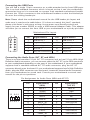
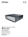
New Solution Series NSK2480 User’s Manual Manuel de l’utilisateur Anwenderhandbuch Manuale per l’operatore Manual del usuario পᡅ䂀ᯢ At Antec, we continually refine and improve our products to ensure the highest quality. As such, your new case may differ slightly from the description in this manual. This isn’t a problem; it’s simply an improvement. As of the date of publication, all features, descriptions, and illustrations in this manual are correct. Disclaimer This manual is intended only as a guide for Antec’s Computer Enclosures. For more comprehensive instructions on installing the motherboard and peripherals, please refer to the user’s manuals that come with those components. New Solution Series User’s Manual NSK 2480 Quiet Desktop Case The Power Supply NSK 2480 comes with an EarthWatts 380 Watt power supply. This universal input, active PFC, single 80mm fan cooled power supply follows the ATX12V version 2.2 specification, and includes dual +12V output rails that deliver safer and more reliable output to your system’s components. EarthWatts power supplies have achieved 80 PLUS® Certification, the latest independent standard in power supply efficiency, and their higher energy efficiency reduces power consumption by up to 25%, saving you money on your electricity bill. In addition EarthWatts includes a variety of protective circuitry: OPP (over power protection), OVP (over voltage protection), and SCP (short circuit protection). The PSU comes with a main power switch. Make sure you turn the switch to the ON (I) position before you boot up the computer for the first time. Normally, you won’t need to switch to the OFF (O) position, since the PSU includes a soft on/off feature. This lets you turn the computer on and off by using the soft switch on the computer case. If the computer crashes and you can’t shut it down using the soft switch, you can switch the main power to the OFF (O) position to shut the system down. Then turn the switch back to the ON (I) position and reboot. Although care has been taken to prevent sharp edges in your Antec case, we strongly recommend taking your time and the appropriate care when working with it. Hurried or careless motion and use of excessive force, particularly when you are working in areas you cannot see clearly, are but a few examples of activity that should be avoided. Please use reasonable precaution. Setting Up 1. 2. 3. Place the case on a flat, stable surface. Remove the thumbscrews from the back of the top panel. Slide the panel towards the rear to remove it from the case. Inside the case you should see the power supply, some wiring with marked connectors (USB, PWR etc.), an installed I/O panel and a power cord. The Triple Chamber structure The case interior is divided into three separate chambers – the power supply chamber, the motherboard chamber and the HDD chamber. This triple chamber structure isolates heat and noise resulting in much quieter and cooler operation 1 than in a traditional desktop case. There are small openings between the chambers to allow for the routing of cables as needed. Installing the Motherboard This manual is not designed to cover CPU, RAM, or expansion card installation. Please consult the motherboard manual for specific mounting instructions and troubleshooting. The motherboard is located inside the main chamber. Two 120mm TriCool™ fans are preinstalled right next to the CPU. 1. 2. 3. 4. 5. 6. 7. 8. Lay the case down so that the open side is up. You should be able to see the drive bay and power supply. Make sure you have the appropriate I/O panel for the motherboard. If the panel provided is not suitable for your motherboard, please contact the motherboard manufacturer for the correct I/O panel. Line up the motherboard with the standoff holes. Determine which holes line up and remember where they are. Not all motherboards will match with all of the provided screw holes, and this is not necessary for proper functionality. Some standoffs may be pre-installed for your convenience. Lift up and remove the motherboard. Screw in the brass standoffs to the threaded holes that line up with the motherboard. Place the motherboard on the brass standoffs. Screw in the motherboard to the standoffs with the provided Phillips-head screws. The motherboard is now installed. Connecting the Power and LED The power supply conforms to the ATX12V Version 2.2 standard. Before you connect the power supply to any of the devices, please consult the appropriate user manuals for the motherboard and other peripherals. 1. 2. 3. 4. 5. Picture 1 Picture 2 Connect the 24-pin Main Power Connector and the 4-pin 12V connector to the motherboard as needed. If the motherboard uses a 20-pin connector; detachthe 4-pin attachment on the 24-pin power connector (see pictures 1 and 2). Note: the detachable 4-pin For 24-pin For 20-pin motherboards section of the main power connector cannot be used motherboards in place of a 4-pin +12V connector. Connect the Reset switch (labeled RESET SW) to the motherboard at the RST connector. Polarity (positive and negative) does not matter for switches. Power Switch (labeled POWER SW) connects to the PWR connector on the motherboard. Power LED connector is a molex connector with blue/white wires. Connect this to any molex connector on the power supply and this will illuminate the circle around the power button when the system is on. Hard Drive LED (labeled HDD LED) connects to the IDE connector. For LEDs, colored wires are positive (+). White or black wires are negative (-). If the LED does not light up when the system is powered on, try reversing the connection. For more info on connecting LEDs to your motherboard, see your motherboard manual. 2 Connecting the USB Ports You will find a single 10-pin connector on a cable attached to the front USB ports. This is an Intel standard connector which is keyed so that it can’t be accidentally, reversed as long as it is connected to a proper Intel standard motherboard header. Connect the 10-pin connector to the motherboard headers so that the blocked pin fits over the missing header pin. Note: Please check the motherboard manual for the USB header pin layout and make sure it matches the table below. If it does not match this Intel® standard, please visit Antec’s web store at http://www.antec.com/StoreFront.bok and search for part number 30095 to order a USB Internal Adapter Cable. This adapter will allow you to connect the front USB to your motherboard on a pin-by-pin basis. Motherboard Pin Layout 1 2 9 10 Pin Signal Names Pin Signal Names 1 USB Power 1 2 USB Power 2 3 Negative Signal 1 4 Negative Signal 2 5 Positive Signal 1 6 Positive Signal 2 7 Ground 1 8 Ground 2 9 Key (No Connection) 10 Empty Pin Connecting the Audio Ports (AC’ 97 and HDA) There is an Intel standard 10-pin AC’ 97 connector and an Intel 10-pin HDA (High Definition Audio) connector, you can connect either the AC’ 97 or the HDA connector to your motherboard depending on the spec of the motherboard. If your motherboard supports Intel’s standard onboard AC’ 97 audio connector, plug the AC’ 97 connector directly onto the board. If your motherboard supports Intel’s High Definition Audio, plug the HDA connector onto the board. Locate the internal audio connectors from your motherboard or sound card. Consult your motherboard or sound card manual for the pin-out positions. Pin Assignment for Audio Ports (HDA and AC’97) 10 6 4 2 97531 Pin Signal Names (HDA) Pin Signal Names (AC’97) 1 MIC2 L 1 MIC In 2 AGND 2 GND 3 MIC2 R 3 MIC Power 4 AVCC 4 NC 5 FRO-R 5 Line Out (R) 6 MIC2_JD 6 Line Out (R) 7 F_IO_SEN 7 NC 8 Key (no pin) 8 Key (no pin) 9 FRO-L 9 Line Out (L) 10 LINE2_JD 10 Line Out (L) 3 Hard disk Drive Installation There is a hard disk drive bracket with soft silicone grommets inside the HDD chamber that can hold two hard drives. 1. 2. 3. 4. 5. Remove the HDD bracket from the chamber by removing the four screws on top of it. Mount the left side of the hard drives (facing from the front of the hard drive) onto the drive bracket through the top silicone grommets with the special screws provided. (See picture 3) Note: Don’t over-tighten the screws. Over-tightening the screws will reduce the vibration and noise-dampening ability of the Picture 3 rubber grommets. Place the HDD/bracket assembly back into the case. Each hard drive should rest on two soft silicone grommets preinstalled at the bottom of the case. It is optional, but not necessary to attach the hard drives with screws through the bottom grommets. Fasten the bracket using the screws provided. Find a 4-pin Molex or a SATA connector on the power supply and connect it to the corresponding power connector on the device. 5.25” Device Installation NSK 2480 incorporates a rapid-release Flip Up Drive Cage inside the power supply chamber for easy drive installation. The cage can hold two 5.25” devices. To install an external 5.25” device: 1. 2. 3. 4. Remove the flip-up drive cage. Remove the corresponding drive bay cover to which you intend to install the device. Insert the 5’25” device into the cage. Fasten the drive with the screws included. (See Picture 4) Find a 4-pin Molex or a SATA connector on the power supply and connect it to the corresponding power connector on the device. Picture 4 Cooling System The 120mm TriCool™ fans The NSK 2480 comes with two 120mm TriCool fans preinstalled. These fans sit right next to the CPU and are installed so that the air is blowing out of the case. Please leave at least 1” (2.5cm) between the right side of the case and anything that would block the exhaust from these fans. Failure to do so may cause the chamber or CPU to overheat. These fans have a three-speed switch that lets you choose between quiet, performance, or maximum cooling. (See specifications below.) Connect a large 4-pin connector from the power supply to the male 4-pin connector on the fan. Note: The default setting of the fans is Low. We recommend this speed to maximize quiet computing. 4 Note regarding using fan speed controllers with TriCool fans: The minimum voltage to start the fan is 5V. We recommend our users set the fan speed to High if the fan will be connected to a fan control device or to the Fan-Only connector found on some Antec power supplies. A fan-control device regulates the fan speed by varying the voltage to it. The voltage may start as low as 4.5 V to 5V. Connecting a TriCool™ set on Medium or Low to a fan-control device may result in the fan not being able to start. The already lowered voltage from the fan control device will be further reduced by the TriCool circuitry below 5V. Specifications Size: Rated Voltage: Operating Voltage: 120 x 120 x 25.4 mm DC 12V 10.2V ~ 13.8V Speed Input Current Air Flow Static Pressure Acoustical Noise Input Power High 2000 RPM 0.24A (Max.) 2.24 m³ / min (79 CFM) 2.54 mm-H2O (0.10 inch-H2O) 30 dBA 2.9 W Medium 1600 RPM 0.2A 1.59 m³ / min (56 CFM) 1.53 mm-H2O (0.06 inch-H2O) 28 dBA 2.4 W Low 1200 RPM 0.13A 1.1 m³ / min (39 CFM) 0.92 mm-H2O (0.04 inch-H2O) 25 dBA 1.6 W The Bottom Air Intake There are intake vents at the bottom of the case right under the HDD chamber. Fresh cool air will flow through the vents through the hard drives, and then flow into the motherboard chamber and exhaust by the two 120mm TriCool fans. Note: Do not place the NSK2480 on a soft surface or over anything that will block the bottom air vents. The Upper Air Intake There are vents on the top panel above the PCI expansion slots. Fresh air will flow through them into the motherboard chamber to cool the VGA card. Note: Do not place anything on top of the NSK2480 that will block the top air vents The Rear Air Intake There are vents right above the rear I/O panel and on the PCI expansion slot covers to bring in fresh air to help cool the CPU and VGA card. CPU Air Guide The CPU Air Guide and rear air intake work together to provide fresh air to the CPU cooler to enhance the CPU cooling. The CPU Air Guide consists of several sections that can be adjusted to best suit each individual motherboard CPU position. The Power Supply Air Intake There are vents on the left side of the case to bring fresh air into the power supply chamber to cool the power supply. Note: Please leave at least 1” (2.5cm) between the left side of the case and 5 anything that could block airflow to the power supply. This is required so that the power supply will have sufficient cooling. Learn more about 80 PLUS®: 80 PLUS® is an innovative, electric utility-funded incentive program to integrate more energy-efficient power supplies into desktop computers and servers. The 80 PLUS performance specifications require power supplies in computers and servers to be 80% or greater energy efficient. This makes an 80 PLUS certified power supply at least 33% more efficient than current power supplies. 80 PLUS certified power supplies: • • • • • • • Achieve energy savings, up to $70 over the life of a desktop computer Reduce a room’s cooling load, increasing comfort and saving up to 30% Increase computer system reliability and save on maintenance costs by as much as 40% Minimize the need for noisy fans, creating a quieter environment Save on construction — saves hundreds of dollars in electrical system upgrades Allow more computers on the same branch circuit Save the environment — prevent pollution by reducing energy consumption Run Cool, Run Reliably, Run with 80 PLUS® Energy Efficient® More than 80% efficient at 20%, 50% & 100% load www.80PLUS.org System Integrators / VAR’s for more information on 80 PLUS® financial and marketing advantages in North America go to www.antec.com/us/80Plus.html. 6 Antec, Inc. 47900 Fremont Blvd. Fremont, CA 94538 USA tel: 510-770-1200 fax: 510-770-1288 Antec Europe B.V. Stuttgartstraat 12 3047 AS Rotterdam The Netherlands tel: +31 (0) 10 462-2060 fax: +31 (0) 10 437-1752 Customer Support: US & Canada 1-800-22ANTEC [email protected] Europe +31 (0) 10 462-2060 [email protected] www.antec.com © Copyright 2007 Antec, Inc. All rights reserved. All trademarks are the property of their respective owners. Reproduction in whole or in part without written permission is prohibited. Printed in China.