1
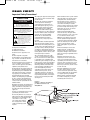
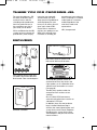
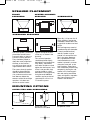
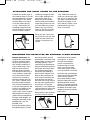
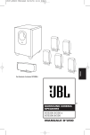
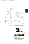
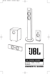
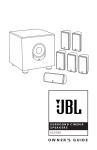
SCS200.5 OM
5/18/06
10:24 AM
Page 1
SURROUND CINEMA
SPEAKERS
SCS200.5
OWNER’S GUIDE
®
SCS200.5 OM
5/18/06
10:24 AM
Page 2
READ FIRST!
Important Safety Precautions!
CAUTION
RISK OF ELECTRIC SHOCK
DO NOT OPEN
CAUTION: To reduce the risk of electric shock,
do not remove cover (or back).
No user-serviceable parts inside.
Refer servicing to qualified service personnel.
CAUTION: To prevent electric shock,
do not use this (polarized) plug with
an extension cord, receptacle or other outlet
unless the blades can be fully inserted to
prevent blade exposure.
The lightning flash with arrowhead symbol,
within an equilateral triangle, is intended to
alert the user to the presence of uninsulated
“dangerous voltage” within the product’s
enclosure that may be of sufficient magnitude to constitute
a risk of electric shock to persons.
The exclamation point within an equilateral
triangle is intended to alert the user to the
presence of important operating and
maintenance (servicing) instructions in the
literature accompanying the appliance.
1. Read these instructions.
2. Keep these instructions.
3. Heed all warnings.
4. Follow all instructions.
5. Do not use this apparatus near
water.
6. Clean only with a dry cloth.
7. Do not block any ventilation openings. Install in accordance with the
manufacturer’s instructions.
8. Do not install near any heat sources
such as radiators, heat registers,
stoves or other apparatus (including
amplifiers) that produce heat.
9. Do not defeat the safety purpose of
the polarized or grounding-type plug.
A polarized plug has two blades with
one wider than the other. A grounding-type plug has two blades and a
third grounding prong. The wide
blade or the third prong are provided
for your safety. If the provided plug
does not fit into your outlet, consult
an electrician for replacement of the
obsolete outlet.
10. Protect the power cord from being
walked on or pinched, particularly at
plugs, convenience receptacles and
the point where they exit from the
apparatus.
11. Only use attachments/accessories
specified by the manufacturer.
12. Use only with the cart, stand, tripod, bracket or table specified by the
manufacturer or sold with the apparatus. When a cart is used,
use caution when moving
the cart/apparatus combination to avoid injury from
tip-over.
2
13. Unplug this apparatus during lightning storms or when unused for long
periods of time.
14. Refer all servicing to qualified
service personnel. Servicing is
required when the apparatus has
been damaged in any way, such as
power-supply cord or plug is damaged, liquid has been spilled or
objects have fallen into the apparatus, the apparatus has been exposed
to rain or moisture, does not operate
normally, or has been dropped.
15. Do not use attachments not
recommended by the product
manufacturer, as they may cause
hazards.
16. This product should be operated
only from the type of power source
indicated on the marking label. If you
are not sure of the type of power supply to your home, consult your product dealer or local power company.
For products intended to operate from
battery power, or other sources, refer
to the operating instructions.
17. If an outside antenna or cable
system is connected to the product,
be sure the antenna or cable system
is grounded so as to provide some
protection against voltage surges and
built-up static charges. Article 810 of
the National Electrical Code, ANSI/
NFPA 70, provides information with
regard to proper grounding of the
mast and supporting structure,
grounding of the lead-in wire to an
antenna discharge unit, size of
grounding conductors, location of
antenna-discharge unit, connection
to grounding electrodes, and requirements for the grounding electrode.
See Figure A.
Figure A.
Example of Antenna Grounding as
per National Electrical Code
ANSI/NFPA 70
18. An outside antenna system should
not be located in the vicinity of overhead power lines or other electric
light or power circuits, or where it
can fall into such power lines or circuits. When installing an outside
antenna system, extreme care should
be taken to keep from touching such
power lines or circuits, as contact
with them might be fatal.
19. Do not overload wall outlets,
extension cords, or integral convenience receptacles, as this can result
in a risk of fire or electric shock.
20. Never push objects of any kind
into this product through openings,
as they may touch dangerous voltage
points or short-out parts that could
result in a fire or electric shock.
Never spill liquid of any kind on the
product.
21. Do not attempt to service this
product yourself, as opening or
removing covers may expose you to
dangerous voltage or other hazards.
Refer all servicing to qualified service
personnel.
22. When replacement parts are
required, be sure the service technician has used replacement parts
specified by the manufacturer or that
have the same characteristics as the
original part. Unauthorized substitutions may result in fire, electric shock
or other hazards.
23. Upon completion of any service
or repairs to this product, ask the
service technician to perform safety
checks to determine that the product
is in proper operating condition.
24. The product should be mounted
to a wall or ceiling only as recommended by the manufacturer.
SCS200.5 OM
5/18/06
10:24 AM
Page 3
THANK YOU FOR CHOOSING JBL
For more than 60 years, JBL
has been involved in every
aspect of music and film
recording and reproduction,
from live performances to
the recordings you play in
your home, car or office.
We’re confident that the JBL
system you have chosen will
provide every note of enjoy-
ment that you expected –
and that when you think
about purchasing additional
audio equipment for your
home, car or office, you will
once again choose JBL.
posted on our latest advancements, and helps us to better
understand our customers
and build products that
meet their needs and
expectations.
Please take a moment to
register your product on our
Web site at www.jbl.com.
It enables us to keep you
JBL, Incorporated
INCLUDED
One center channel speaker with
shelf stand. Wall-mount bracket.
Four satellites for left, right and
surrounds. Wall-mount brackets.
Shelf stands. Floor stand adapters.
Three 20' (6m) speaker cables for
connection to front, left, center and
right speakers, or to subwoofer when
speaker-level connections are used
(see page 9).
Two 40' (12m) speaker cables for
connection from receiver to rear
satellites.
One 15' (4.6m) RCA interconnect
cable for connection from receiver to
subwoofer’s LFE input.
Powered subwoofer.
In addition, there are two hardware
bags included. Hardware Bag A
contains the metal tightening bar and
screws for the shelf stands. Hardware
Bag B contains screws for the floor
stand adapters and parts for the wallmount brackets.
3
SCS200.5 OM
5/18/06
10:24 AM
Page 4
SPEAKER PLACEMENT
FRONT
SPEAKERS
CENTER CHANNEL
SPEAKER
SUBWOOFER
0–2 ft
(0–0.6m)
SURROUND SPEAKERS
5–6 ft
(1.5–1.8m)
The front speakers should be
placed the same distance
from each other as they are
from the listening position.
They should be placed at
about the same height from
the floor as the listeners’
ears will be, or they may be
angled toward the listeners.
The center channel speaker
should be placed directly
above or below the television, and no more than two
feet above or below the
tweeters of the left and right
speakers. It is often convenient to set the center
speaker on top of the television set, as shown in the
drawing.
The surround speakers
should be placed slightly
behind the listening position
and, ideally, should face
each other and be at a level
higher than the listeners’ ears.
If that is not possible, they
may be placed on a wall
behind the listening position,
facing forward. Additional
satellites may be purchased
separately for use in 6.1- or
7.1-channel systems.
Generally, it is best to aim all
of the speakers (except the
subwoofer) toward the listening position at about ear-level
height.
The low-frequency material
reproduced by the subwoofer
is mostly omnidirectional,
and this speaker may be
placed in a convenient location in the room. However,
bass reproduction will be
maximized when the subwoofer is placed in a corner
along the same wall as the
front speakers. Experiment
with subwoofer placement by
temporarily placing the subwoofer in the listening position and moving around the
room until the bass reproduction is best. Place the subwoofer in that location.
MOUNTING OPTIONS
SATELLITES AND SURROUNDS
On shelves.
4
On the wall. Wall
brackets are included.
On optional stands.
SCS200.5 OM
5/18/06
10:24 AM
Page 5
ATTACHING THE SHELF STAND TO THE SPEAKER
Prepare the speaker wire as
described on page 7. Thread
the two conductors through
the two holes in the stand
bracket. Make sure to preserve the proper polarity
(+ and – connections) by
threading the positive conductor through the hole on
the left, and the negative
conductor through the hole
on the right, looking at the
front of the stand. Push
down on the red speaker
terminal and insert the bare
end of the positive wire into
the hole under the red cap.
Release the cap, and tug
gently on the wire to make
sure that the connection is
snug. Follow the same procedure to connect the negative wire to its terminal. Use
the larger screw (Hardware
Bag A) in the upper screw
hole, and the smaller screw
(Hardware Bag A) in the
lower screw hole.
Gently pull the slack out of
the wire and screw the shelf
stand onto the back of the
speaker in two places, as
shown.
MOUNTING THE SATELLITES ON OPTIONAL FLOOR STANDS
Important Safety Note: The
supplied floor stand adapters
facilitate installation with a
variety of general-purpose
floor stands available from
many manufacturers. Since
different stands will have
different weight capacities
and stability characteristics, it
is the customer’s responsibility to check with the stand
manufacturer or dealer to
determine whether that specific stand is capable of handling the weight and proportions of these loudspeakers in
a safe and stable manner. JBL
disclaims any liability for the
selection of suitable floor
stands and/or correct compatibility between the selected
stand and these loudspeakers.
The floor stand adapters are
compatible with floor
+ stands
–
equipped with a 1/4"-20
threaded insert.
Prepare the speaker wire as
described on page 7. Thread
the two conductors through
the two holes in the floor stand
adapter. Make sure to preserve
the proper polarity (+ and –
connections) by threading the
positive conductor through the
hole on the left, and the negative conductor through the
hole on the right (looking at
the front of the adapter). Push
down on the red speaker terminal and insert the bare end
of the positive wire into the
hole under the red cap. Release
the cap, and tug gently on the
wire to make sure that the
connection is snug. Follow the
same procedure to connect the
negative wire to its terminal.
Gently pull the slack out of the
wire and screw the adapter
+
onto the back of the speaker
in two places, as shown.
The floor stand adapter
screws may be found in
Hardware Bag B. Use the
larger screw in the upper
screw hole, and the smaller
screw in the lower screw hole.
Screw the floor stand adapter
into the floor stand’s threaded
insert until the speaker is
firmly attached to the stand.
Back off slightly from the fully
tightened position until the
speaker is oriented as desired,
then rotate the thumbwheel at
the bottom of the floor stand
adapter to secure the speaker
to the stand.
–
5
SCS200.5 OM
5/18/06
10:24 AM
Page 6
WALL-MOUNTING
4
3
Step 5: Tighten the Metal
Nut ¡ with the star washer
side between the Nut ¡
and the back of the Satellite
Speaker ¶, using large
needle-nose pliers, until it
is firmly seated against the
back of the Speaker ¶ and
has locked the Ball and
Shaft £ and the Speaker
¶ together. Note that once
the Metal Nut ¡ is fully
tightened, it may embed
some marks on the back of
the Satellite Speaker ¶.
However, these marks will
be covered by the Metal
Nut ¡.
Step 6: Mount the Attachment
Plate ¢ into a wood stud on
the wall, using four #10 panhead wood screws at least
2
1
8
5
Important Safety Note: The
customer is solely responsible for proper selection of
mounting hardware not
included with the speakers,
and for proper assembly
and installation of the wall
brackets, including but not
limited to the selection of
appropriate weight-bearing
supports and proper use of
the bracket. JBL disclaims
any liability for the selection
of mounting hardware
and/or bracket installation.
Be sure to follow these
bracket assembly and
installation instructions
carefully. If you have any
questions or doubts about
your ability to correctly wallmount the speakers, consult
with your authorized JBL
dealer or custom installer.
Step 1: Unscrew and remove
the large Molded Nut ™. If
necessary, use the supplied
Metal Bar ∞ as a lever by
inserting it into one of the
holes in the outer edge of
the Molded Nut ™.
Step 2: Firmly grasp the Ball
and Shaft £ and pull it
straight out of the Attachment Plate ¢. Avoid leaning
it to the side for leverage, as
this may break off a tab.
6
Step 3: Slide the Molded Nut
™ onto the Ball and Shaft £
with the threaded opening
facing the ball. Thread the
Metal Nut ¡ all the way
onto the Ball and Shaft £,
with the star washer side
away from the ball. Refer
to the exploded drawing for
the proper orientation of
these parts.
7
6
1
2
5
Step 4: Screw the Ball and
Shaft £ into the Threaded
Insert § on the back of
the Satellite Speaker ¶
until it is fully seated in the
Threaded Insert §, but do
not tighten, as you might
dislodge the Threaded
Insert §. Such damage
would not be covered under
the warranty.
3
4
8
one-inch long (not supplied)
•. Make sure that all four
screws are driven into the
stud and not into drywall.
If the bracket needs to be
mounted in drywall, the
customer is responsible for
selecting and using appropriate wall anchors and screws.
Important Note: The Metal
Nut ¡ must be fully tightened against the Satellite
SCS200.5 OM
5/18/06
10:24 AM
Speaker ¶ as described in
Step 5 before beginning Step
7, in order to avoid damage
to the Threaded Insert §.
Such damage would not be
covered under the warranty.
Step 7: Holding the Satellite
Speaker ¶ with both hands,
reinsert the ball portion of
the Ball and Shaft £ into
the Attachment Plate ¢.
Step 8: Hand-tighten the
Molded Nut ™ while positioning the speaker for the
desired orientation. If the
Molded Nut ™ is difficult to
tighten by hand, insert the
Metal Bar ∞ into one of the
Page 7
holes in the outer edge of
the Molded Nut ™ and use
the bar as a lever. Be careful
not to cross-thread. The
swiveling ball enables you to
aim the speaker to one side
or the other, or to tilt it up
or down. Although stereo
imaging may be improved
by aiming the front speakers
toward the listening position,
especially for music selections, the surround speakers
are intended to provide a
diffuse, ambient sound that
is best achieved by aiming
the speakers straight out
from the wall. Aiming the
surround speakers toward
the listening position may
ruin the intended effect by
calling too much attention
to the information in those
channels.
Step 9: Once the speaker’s
orientation has been finalized, insert the Metal Bar ∞
into one of the holes in the
outer edge of the Molded
Nut ™ and tighten the
Molded Nut ™ securely.
Keep the Metal Bar ∞ in a
safe place, in the event that
you decide to adjust the
speaker’s orientation in
the future.
SPEAKER CONNECTIONS
CONNECTION TIPS
Separate and strip the
ends of the speaker wire,
as shown. The wires supplied with the system may
already be stripped and
tinned for easy insertion into
the speaker terminals. You
may need to separate the
two conductors further in
order to thread them through
the shelf stand or floor stand
adapter. Speakers and electronics terminals have corresponding (+) and (–) terminals. Most manufacturers of
speakers and electronics,
including JBL, use red to
denote the (+) terminal and
black to denote the (–)
terminal.
The (+) lead of the speaker
wire is noted with a stripe. It
is important to connect both
speakers identically: (+) on
the speaker to (+) on the
amplifier and (–) on the
speaker to (–) on the amplifier.
Wiring “out of phase” results
in thin sound, weak bass and
a poor stereo image.
With the advent of multichannel surround sound
systems, connecting all of
the speakers in your system
with the correct polarity
remains equally important in
order to preserve the proper
ambience and directionality
of the program material.
To connect the supplied
speaker wires to the satellite
and center speaker terminals, press the red or black
plastic cap for the desired
terminal, insert the bare end
of the wire into the hole
below the cap and release
the cap. Gently tug on the
wire to make sure that it is
fully inserted.
To use the binding-post
speaker terminals on the
subwoofer, unscrew the
colored collar until the passthrough hole in the center
post is visible under the
collar. Insert the bare end of
the wire through this hole;
then screw the collar down
until the connection is tight.
The hole in the center of each
collar is intended for use
with banana-type connectors.
To comply with European CE
certification, these holes are
blocked with plastic inserts at
the point of manufacture. To
use banana-type connectors
requires the removal of the
inserts. Do not remove these
inserts if you are using the
product in an area covered by
the European CE certification.
7
SCS200.5 OM
5/18/06
10:24 AM
Page 8
DOLBY® DIGITAL OR DTS®
(OR OTHER DIGITAL SURROUND MODE) CONNECTION
SUBWOOFER
RECEIVER
LINE LFE
LEVEL
IN
LFE OUT
L
Connect this jack to the LFE
output or subwoofer output
on your receiver or amplifier.
Connect each speaker to the
corresponding speaker
terminals on your receiver
or amplifier.
R
Use this installation method
for Dolby® Digital, DTS® or
other digital surround
processors:
Make sure that you have
configured your surround
sound processor for
“Subwoofer On.” The front
left, front right, center and
Use the line-level input jack
marked “LFE” for the LowFrequency Effects channel.
surround speakers should
all be set to “Small.” If your
receiver allows you to set
the crossover frequency
between the subwoofer and
the main speakers, select
120Hz or the setting that is the
closest frequency below it.
DOLBY PRO LOGIC® (NON-DIGITAL) – LINE LEVEL
Use RCA-type interconnects
to connect the line-level
subwoofer outputs on your
receiver or amplifier to the
line-level inputs on the subwoofer. IMPORTANT: Do not
use the LFE input on the subwoofer with Dolby Pro Logic
processors.
Use this installation method
for Dolby Pro Logic® applications (not Dolby Digital, DTS
or other digital processing),
where the receiver/processor is equipped with a subwoofer output, or a volumecontrolled preamp (line-)
level output:
Center
Left Front
–
–
+
Right Front
+
–
+
Subwoofer
LineLevel In
Connect each speaker to
the corresponding speaker
terminals on your receiver
or amplifier.
L
R
Receiver
–
+
Subwoofer
Out
Left
Front
–
+
Left
Surround
Left
Surround
–
8
+
–
R
Right
Front
–
+
L
+
Center
Surround Back
Surround Back
Left
Right
–
+
Surround Back
Left
–
+
NOTE: If your receiver or
amplifier has only one subwoofer output jack, then you
will need to use a Y-connector (not included). Plug the
male end of the Y-connector
into your receiver or amplifier’s subwoofer output jack,
and connect each of the two
female ends to separate
RCA-type interconnects.
Finally, plug the RCA-type
interconnects into the linelevel inputs on the subwoofer.
–
+
Surround Back
Right
–
+
Make sure your receiver or
processor is correctly configured to indicate that the
subwoofer is “On.”
Right
Surround
–
+
Right
Surround
–
+
Note for advanced users: If
your receiver/processor has
a built-in low-pass crossover
filter for the subwoofer output, you may use the LFE
input to bypass the subwoofer’s internal crossover.
SCS200.5 OM
5/18/06
10:24 AM
Page 9
DOLBY PRO LOGIC (NON-DIGITAL) – SPEAKER LEVEL
Use this installation method
for Dolby Pro Logic applications (not Dolby Digital, DTS
or other digital processing),
where the receiver/processor
does not have a subwoofer
output, or a volume-controlled
preamp (line-) level output:
Center
Subwoofer
Connect your receiver or
amplifier’s front left and right
speaker terminals to the left
and right terminals on the
subwoofer that are marked
“Speaker Level In.” Connect
the left and right terminals
on the subwoofer that are
marked “Speaker Level Out”
to the corresponding terminals on the back of your front
left and right speakers.
Connect your receiver or
amplifier’s center, surround
and surround back speaker
terminals to the corresponding terminals on the back of
your center and surround
speakers.
Right Front
Left Front
OUT
IN
+
+
–
–
–
–
+
+
R
L
R
L
S
P
E
A
K
E
R
L
E
V
E
L
Receiver
Left Front
Left Surround
Left Surround
Center
Right Front
Right Surround
Right Surround
9
SCS200.5 OM
5/18/06
10:24 AM
Page 10
OPERATION
Move the Master Power
switch (marked “Power” å)
to the “•” (On) position to
use the SUB200 subwoofer.
∫
If you will be away from
home for an extended period
of time, or if the subwoofer
will not be used, switch the
Master Power switch å to
the Off position.
å
VOLUME
Volume may be adjusted
using the Subwoofer Level
control ∫ as shown.
10
SCS200.5 OM
5/18/06
10:24 AM
Page 11
TROUBLESHOOTING
If there is no sound from any
of the speakers:
• Check that receiver/amplifier is on and a source is
playing.
• Check that the powered
subwoofer is plugged in,
and its Power switch å is
switched on (“•” position).
• Check all wires and connections between receiver/
amplifier and speakers.
Make sure all wires are connected. Make sure none of
the speaker wires are
frayed, cut or punctured, or
touching each other.
• Review proper operation of
your receiver/amplifier.
If there is no sound coming
from one speaker:
• Check the “Balance” control
on your receiver/amplifier.
• Check all wires and connections between receiver/
amplifier and speakers.
Make sure all wires are connected. Make sure none of
the speaker wires are
frayed, cut or punctured, or
touching each other.
• In Dolby Digital or DTS
modes, make sure that the
receiver/processor is configured so that the speaker in
question is enabled.
• Turn off all electronics
and switch the speaker in
question with one of the
other speakers that are
working correctly. Turn
everything back on, and
determine whether the
problem has followed the
speaker, or has remained
in the same channel. If the
problem is in the same
channel, the source of the
problem is most likely with
your receiver or amplifier,
and you should consult the
owner’s manual for that
product for further information. If the problem has followed the speaker, consult
your dealer for further assistance or, if that is not possible, visit www.jbl.com.
If there is no sound from the
center speaker:
• Check all wires and connections between receiver/
amplifier and speaker. Make
sure all wires are connected.
Make sure none of the
speaker wires are frayed,
cut or punctured, or touching each other.
• If your receiver/processor
is set in Dolby Pro Logic mode,
make sure the center speaker
is not in phantom mode.
• If your receiver/processor
is set in one of the Dolby
Digital or DTS modes, make
sure the receiver/processor
is configured so that the
center speaker is enabled.
If the system plays at low
volumes but shuts off as
volume is increased:
• Check all wires and connections between receiver/
amplifier and speakers.
Make sure all wires are connected. Make sure none of
the speaker wires are
frayed, cut or punctured, or
touching each other.
• If more than one pair of
main speakers is being used,
check the minimum impedance requirements of your
receiver/amplifier.
If there is low (or no) bass
output:
• Make sure the connections
to the left and right “Speaker
Inputs” have the correct
polarity (+ and –).
• Make sure the subwoofer
is plugged into an active
electrical outlet, and is
turned on (Power switch å
in the “•” position).
• In Dolby Digital or DTS
modes, make sure your
receiver/processor is configured so that the subwoofer
and LFE output are enabled.
If there is no sound from
the surround speakers:
• Check all wires and connections between receiver/
amplifier and speakers.
Make sure all wires are connected. Make sure none of
the speaker wires are
frayed, cut or punctured, or
touching each other.
• Review proper operation of
your receiver/amplifier and
its surround sound features.
• Make sure the movie or
TV show you are watching
is recorded in a surround
sound mode. If it is not,
check to see whether your
receiver/amplifier has other
surround modes you may use.
• In Dolby Digital or DTS
modes, make sure your
receiver/processor is configured so that the surround
speakers are enabled.
• Review the operation of
your DVD player and the
jacket of your DVD to make
sure that the DVD features
the desired Dolby Digital or
DTS mode, and that you
have properly selected that
mode using both the DVD
player’s menu and the DVD
disc’s menu.
11
SCS200.5 OM
5/18/06
10:24 AM
Page 12
SPECIFICATIONS
SCS200.5
SUBWOOFER
Frequency Response
35Hz – 20kHz (–6dB)
Amplifier 100 Watts RMS
Frequency Response 35Hz – 160Hz (–6dB)
Woofer 8" (200mm)
Enclosure Bass-reflex
Dimensions (H x W x D) (including feet)
16-1/4" x 11" x 13-3/4" (413mm x 279mm x 349mm)
Weight 28 lb (12.7kg)
SATELLITES
Maximum Recommended Amplifier Power
100 Watts
Power Handling (Continuous/Peak)
50W/160W
Nominal Impedance 8 Ohms
Sensitivity 86dB @ 1 Watt/1 meter
Frequency Response 110Hz – 20kHz (–6dB)
Tweeter
1/2" (13mm) Titanium-laminate dome,
video-shielded
Midrange
3" (75mm) Driver, video-shielded
Dimensions (H x W x D) (not including shelf stands)
7-1/4" x 4" x 3-1/2" (184mm x 102mm x 89mm)
Weight 1.75 lb (0.8kg)
All features and specifications are subject to change
without notice.
Dolby and Pro Logic are registered trademarks of
Dolby Laboratories.
DTS is a registered trademark of DTS, Inc.
CENTER
Maximum Recommended Amplifier Power
100 Watts
Power Handling (Continuous/Peak)
50W/200W
Nominal Impedance 8 Ohms
Sensitivity
88dB @ 1 Watt/1 meter
Frequency Response 100Hz – 20kHz (–6dB)
Tweeter
1/2" (13mm) Titanium-laminate dome,
video-shielded
Midrange
Dual 3" (75mm) drivers, video-shielded
Dimensions (H x W x D) (not including shelf stand)
4" x 11-1/2" x 3-1/2" (102mm x 292mm x 89mm)
Weight 3 lb (1.4kg)
OWNER’S GUIDE
PRODUCT
SURROUND CINEMA
SPEAKERS
MODELS:
PRO SOUND
COMES HOME™
LINE:
SCS200.5
JBL, Incorporated
250 Crossways Park Drive, Woodbury, NY 11797
8500 Balboa Boulevard, Northridge, CA 91329
516.255.4JBL (4525) (USA only)
www.jbl.com
DESIGN GOAL: Bring the thrill of live performance and movie sound
to the home environment by calling on JBL’s professional engineering leadership.
© 2006 Harman International Industries, Incorporated.
All rights reserved.
SATELLITE TYPE: Titanium-laminate-dome tweeter,
sealed enclosure
SUBWOOFER TYPE: Bass-reflex enclosure
JBL and Harman International are trademarks of Harman
International Industries, Incorporated, registered in the
United States and/or other countries.
PORT DESIGN: FreeFlow™ flared
Part No. 406-000-05457-E
12
PROFESSIONAL REFERENCE: Cinema Loudspeaker Series