1
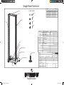
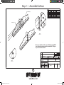
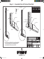
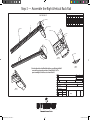
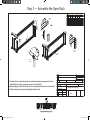
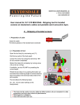
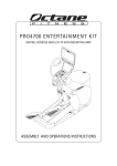
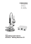
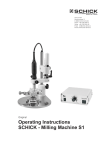
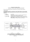
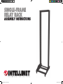
SINGLE-FRAME
RELAY RACK
ASSEMBLY INSTRUCTIONS
Single Frame_ass_instrux.indd 1
10/26/06 9:21:36 AM
Single Rack Parts List
iSO 2768-m
TOLERANCE
C
ASSEMBLY HARDWARE
>=
<
M8X15
C
Deviation
Basic dimension
M8
Linear dim.
Deviation
Shorter side
Broken edges
<
>=
Degrees
0.5
3
-
10˚
± 1˚
6
± 0.1
± 0.1
± 0.2
3
± 0.5
10˚
50˚
± 0˚30'
6
30
± 0.2
±1
50˚
120˚
± 0˚20'
30
120
± 0.3
±1
120˚
400˚
± 0˚10'
120
400
± 0.5
±1
400˚
-
± 0˚5'
400
1000
± 0.8
±1
1000
2000
± 1.2
±1
D
M8
D
M8
PART NO.
A
B
C
D
LEVELING FEET
M8X15
M8
M8
M8
C
C
PART DESCRIPTION
Base, Right Side
Base, Left Side
Horizontal Support
Vertical Rack Rail
Leveling Feet
Channel Screw
Nut
Washer
Spring Washer
QUANTITY INCLUDED
2
2
5
2
4
32
32
32
32
A (BASE - RIGHT SIDE)
B (BASE - LEFT SIDE)
LEVELING FEET
REV
00
ITEM NO.
NOMENCLATURE OR DESCRIPTION
PART OR IDENTIFYING NO.
LEVELING FEET 4X
PARTS
MATERIAL:
QTY.
RQD.
MATERIAL SPECIFICATION
LIST
FINISH
CRS1110 (A1)
CAD-GENERATED DRAWING
DO NOT MANUALLY UPDATE
DO NOT SCALE DRAWING
APPROVALS
C
Single Frame_ass_instrux.indd 2
DRAWN
DATE
SIZE
DWG NO.
SHEET OF
REV
:
00
CHECKED :
10/26/06 9:21:36 AM
Step 1 — Assemble the Base
iSO 2768-m
TOLERANCE
Basic dimension
>=
<
RIGHT BASE (A)
Deviation
Liner dim.
Deviation
Shorter side
Broken edges
<
>=
Degrees
-
10˚
± 1˚
3
± 0.1
3
6
± 0.1
± 0.2
± 0.5
10˚
50˚
± 0˚30'
6
30
± 0.2
±1
50˚
120˚
± 0˚20'
30
120
± 0.3
±1
120˚
400˚
± 0˚10'
120
400
± 0.5
±1
400˚
-
± 0˚5'
400
1000
± 0.8
±1
1000
2000
± 1.2
±1
0.5
1
LEFT BASE (B)
2
DETAIL 1
SCALE 1 : 2
1) Join one piece of right base A with one piece of left base B using the M8X15
screws, washers, spring washers and nuts as shown in Details 1 & 2. Repeat
the process for the other set of A & B.
REV
00
ITEM NO.
NOMENCLATURE OR DESCRIPTION
PART OR IDENTIFYING NO.
PARTS
MATERIAL:
DETAIL 2
SCALE 1 : 2
QTY.
RQD.
MATERIAL SPECIFICATION
LIST
FINISH
CRS1110 (A1)
CAD-GENERATED DRAWING
DO NOT MANUALLY UPDATE
SINGLE FRAME RELAY RACK ASSEMBLY INSTRUCTIONS
DO NOT SCALE DRAWING
APPROVALS
DATE
SIZE
DWG NO
SHEET OF
REV
DRAWN:
CHECKED:
Single Frame_ass_instrux.indd 3
STEP_1
00
10/26/06 9:21:38 AM
Step 2 — Assemble the Left Vertical Rack Rail
LEFT BASE GROUP
Basic dimension
PROFILE
Deviation
Liner dim.
3
± 0.1
3
6
6
30
30
0.5
PROFILE
D
>=
<
Square holes
3
iSO 2768-m
TOLERANCE
Deviation
Shorter side
Broken edges
<
>=
Degrees
-
10˚
± 1˚
± 0.1
± 0.2
± 0.5
10˚
50˚
± 0˚30'
± 0.2
±1
50˚
120˚
± 0˚20'
120
± 0.3
±1
120˚
400˚
± 0˚10'
120
400
± 0.5
±1
400˚
-
± 0˚5'
400
1000
± 0.8
±1
1000
2000
± 1.2
±1
DETAIL 3
SCALE 1 : 3
M8 NUT
LEFT BASE (B)
LEFT BASE (B)
M8 SPRING WASHER
RIGHT BASE (A)
M8 WASHER
M8X15 CHANNEL SCREW
RIGHT BASE (A)
DETAIL 1
SCALE 1 : 4
DETAIL 2
SCALE 1 : 4
2
1
REV
00
ITEM NO.
NOMENCLATURE OR DESCRIPTION
PART OR IDENTIFYING NO.
PARTS
MATERIAL:
1) Join the left vertical rack rail D with the left base group A/B using the M8x15
screws, washers, spring washers and nuts as shown in Details 1 & 2. The
square mounting holes should face out as shown in Detail 3.
QTY.
RQD.
MATERIAL SPECIFICATION
LIST
FINISH
CRS1110 (A1)
CAD-GENERATED DRAWING
DO NOT MANUALLY UPDATE
SINGLE FRAME RELAY RACK ASSEMBLY INSTRUCTIONS
DO NOT SCALE DRAWING
APPROVALS
DATE
SIZE
DWG NO
SHEET OF
REV
DRAWN:
CHECKED:
Single Frame_ass_instrux.indd 4
STEP_2
00
10/26/06 9:21:38 AM
Step 3 — Assemble the Right Vertical Rack Rail
Basic dimension
>=
<
RIGHT BASE (A)
D
Deviation
Liner dim.
3
± 0.1
3
6
6
30
30
0.5
1
iSO 2768-m
TOLERANCE
RIGHT BASE GROUP
Deviation
Shorter side
Broken edges
<
>=
Degrees
-
10˚
± 1˚
± 0.1
± 0.2
± 0.5
10˚
50˚
± 0˚30'
± 0.2
±1
50˚
120˚
± 0˚20'
120
± 0.3
±1
120˚
400˚
± 0˚10'
120
400
± 0.5
±1
400˚
-
± 0˚5'
400
1000
± 0.8
±1
1000
2000
± 1.2
±1
LEFT BASE (B)
PROFILE
CHANNEL SCREW
WASHER
NUT
PROFILE
2
AS SHOWN
3
DETAIL 1
SCALE 1 : 3.5
DETAIL 3
SCALE 1 : 2
1) Join the right vertical rack rail D with the right base group A/B using the M8x15
screws, washers, spring washers and nuts as shown in Details 1 & 2. The
square mounting holes should face out as shown in Detail 3.
REV
00
ITEM NO.
NOMENCLATURE OR DESCRIPTION
PART OR IDENTIFYING NO.
PARTS
MATERIAL:
FINISH
CRS1110 (A1)
CAD-GENERATED DRAWING
DO NOT MANUALLY UPDATE
DETAIL 2
SCALE 1 : 5
QTY.
RQD.
MATERIAL SPECIFICATION
LIST
SINGLE FRAME RELAY RACK ASSEMBLY INSTRUCTIONS
DO NOT SCALE DRAWING
APPROVALS
DATE
SIZE
DWG NO
SHEET OF
REV
DRAWN:
CHECKED:
Single Frame_ass_instrux.indd 5
STEP_3
00
10/26/06 9:21:39 AM
Step 4 — Assemble the Horizontal Support Rails
iSO 2768-m
TOLERANCE
Basic dimension
>=
<
PROFILE
DETAIL 1
SCALE 2 : 13
3
PROFILE
Deviation
Liner dim.
Deviation
Shorter side
Broken edges
<
>=
Degrees
0.5
3
± 0.1
10˚
± 1˚
6
± 0.1
± 0.2
± 0.5
-
3
10˚
50˚
± 0˚30'
6
30
± 0.2
±1
50˚
120˚
± 0˚20'
30
120
± 0.3
±1
120˚
400˚
± 0˚10'
120
400
± 0.5
±1
400˚
-
± 0˚5'
400
1000
± 0.8
±1
1000
2000
± 1.2
±1
DETAIL 2A
SCALE 1 : 3
DETAIL 3
SCALE 1 : 4
D
BASE GROUP A/B
LEVELING FEET MOUNTATION
1
M8X15 CHANNEL SCREW
2B
DETAIL 2B
SCALE 1 : 5
2A
LEVELING FEET
HORIZONTAL SUPPORT (C)
REV
00
ITEM NO.
1) Attach three horizontal support rails C to the bottom right-side rack assembly using the M8x15 screws, washers,
spring washers and nuts as shown in Detail 1.
2) Attach the leveling feet to the bottom of the rack assembly using the M8 washer and nut as shown in Details 2A & 2B.
3) Attach two horizontal support rails C to the top right-side rack assembly using the M8x15 screws, washers, spring
washers and nuts as shown in Detail 3.
PARTS
MATERIAL:
QTY.
RQD.
MATERIAL SPECIFICATION
LIST
FINISH
CRS1110 (A1)
CAD-GENERATED DRAWING
DO NOT MANUALLY UPDATE
SINGLE FRAME RELAY RACK ASSEMBLY INSTRUCTIONS
DO NOT SCALE DRAWING
APPROVALS
DATE
SIZE
DWG NO
SHEET OF
REV
DRAWN:
CHECKED:
Single Frame_ass_instrux.indd 6
NOMENCLATURE OR DESCRIPTION
PART OR IDENTIFYING NO.
STEP_4
00
10/26/06 9:21:41 AM
Step 5 — Assemble the Open Rack
iSO 2768-m
TOLERANCE
Basic dimension
>=
<
1
DETAIL 1
SCALE 1 : 4
Deviation
Liner dim.
Deviation
Shorter side
Broken edges
<
>=
Degrees
0.5
3
± 0.1
10˚
± 1˚
6
± 0.1
± 0.2
± 0.5
-
3
10˚
50˚
± 0˚30'
6
30
± 0.2
±1
50˚
120˚
± 0˚20'
30
120
± 0.3
±1
120˚
400˚
± 0˚10'
120
400
± 0.5
±1
400˚
-
± 0˚5'
400
1000
± 0.8
±1
1000
2000
± 1.2
±1
2
D
C
3
DETAIL 2
SCALE 1 : 4
PROFILE
DETAIL 3
SCALE 1 : 4
REV
00
ITEM NO.
1) Join the left-side rack assembly to the right-side rack assembly by attaching the right-side support rails to the left
using the M8x15 screws, washers, spring washers and nuts as shown in Details 1 & 2.
2) Attach the leveling feet to the bottom of the left-side rack assembly using the M8 washer and nut as shown in Detail 3.
3) Stand the rack upright on the leveling feet and firmly tigthen all nuts and bolts.
NOMENCLATURE OR DESCRIPTION
PART OR IDENTIFYING NO.
PARTS
MATERIAL:
QTY.
RQD.
MATERIAL SPECIFICATION
LIST
FINISH
CRS1110 (A1)
CAD-GENERATED DRAWING
DO NOT MANUALLY UPDATE
SINGLE FRAME RELAY RACK ASSEMBLY INSTRUCTIONS
DO NOT SCALE DRAWING
APPROVALS
DATE
SIZE
DWG NO
SHEET OF
REV
DRAWN:
CHECKED:
Single Frame_ass_instrux.indd 7
STEP_5
00
10/26/06 9:21:43 AM
www.intellinet-network.com
Are you completely satisfied with this product?
Please contact your INTELLINET NETWORK SOLUTIONS™ dealer
with comments or questions.
Copyright © INTELLINET NETWORK SOLUTIONS
All products mentioned are trademarks or registered trademarks of their respective owners.
Single Frame_ass_instrux.indd 8
10/26/06 9:21:45 AM