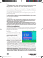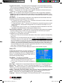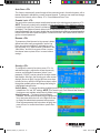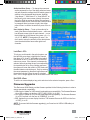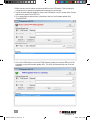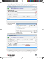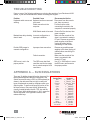
1
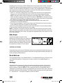
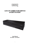
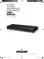
8-Port /
16-Port
Rackmount
KVM Switch
user
manual
Models 524629
& 524643
Shown: 16-Port, Model 524643
INT-524629/524643-UM-0309-01
524629_524643_01_man.indd 1
3/9/09 9:22:10 AM
524629_524643_01_man.indd 2
3/9/09 9:22:10 AM
Thank you for purchasing this INTELLINET NETWORK SOLUTIONS™ Rackmount KVM Switch,
Model 524629 (8-Port) or Model 524643 (16-Port).
Designed for computer/server management on a central console in corporate, factory and
campus computing environments, it provides an on-screen display (OSD) for intuitive KVM
switching operations, and its cascading feature can help upscale the number of connected
computers. A dedicated controller is featured on each port to keep the mouse and keyboard
alive even when the switch isn’t powered on. Excellent video quality with minimal degradation
is guaranteed even when daisy-chained (up to 64 units for Model 524629 and up to 256 units
for Model 524643), and perfect keyboard/mouse emulation provides high compatibility with
PCs, servers and various operating systems.
The easy-to-follow instructions in this user manual help make setup and operation relatively
quick and simple, so you’ll also soon be enjoying the benefits of these additional features:
• USB and PS/2 interface support on both console and PC side
• Computer selection and operation using front-panel push buttons, keyboard hotkeys and OSD menu
• Hot Plug and Play: no need to shut down the KVM switch to attach or remove PCs
• Numerical display and LED indicators for easy bank/port status monitoring
• Supports 2048 x 1536 resolution
• Supports Microsoft and Logitech standard 5-key mice and compatible models
• Buzzer sound for hotkey and port switching confirmation
• Auto-Scan period programmable via OSD menu option
• Password protection
• Auto-logout timeout support
• 4-in-1 connection cable (505727) included — additional connection cables (505727, 505734
or 505840) required per port
• Lifetime Warranty
NOTE: Some screen and product images are modified to fit the format of this manual.
FCC Statement
This device generates and uses radio frequency and may cause interference to radio and
television reception if not installed and used properly. This has been tested and found to comply
with the limits of a Class B computing device in accordance with the specifications in Part 15
of the FCC Rules. These specifications are designed to provide reasonable protection against
such interference in a residential installation. However, there is no guarantee that interference
will not occur in a particular installation. If this device does cause harmful interference to radio
or television reception, which can be determined by turning the device off and on, the user can
try to correct the interference by one or more of the following measures:
• Reorient or relocate the receiving antenna.
• Increase the separation between the device and receiver.
• Connect the computer to an outlet on a circuit different from that to which the receiver is
connected.
• Consult the dealer or an experienced radio/TV technician for help.
3
524629_524643_01_man.indd 3
3/9/09 9:22:10 AM
installation/setup
Front Panel
Shown here: 8-Port, Model 524629
Selected
On Line
1
2
3
4
5
6
7
8
Reset
Power
Selected LED — Lighted red indicates that the PC (or cascaded KVM switch) connected to the corresponding rear-panel port (matching the numbered button beneath the LED) is selected.
Online LED — Lighted green indicates the corresponding PC (or cascaded switch) is ready
(connected but not selected).
Buttons — Press any button (1-8 for Model 524629, 1-16 for Model 524643) to select — or
switch to — the corresponding port/channel for operation. NOTE: See the Operation section
for hotkey and OSD alternatives to pressing a button if the front panel is out of reach or is
otherwise not easily accessible.
Reset — Press this recessed button (using a narrow/pointed object, such as a common pin)
to reset the system.
Power — Lighted green indicates the KVM Switch is powered on. NOTE: A 5 V DC, 2 A
external power adapter is included with this Rackmount KVM Switch.
Rear Panel
Shown here: 16-Port, Model 524643
16
15
14
13
8
7
6
5
Console
DC 5V
F/W
Upgrade
DC 5V — Plug the included external power adapter into this jack and connect to an A/C outlet. Confirm that the Power LED lights on the front panel. CAUTION:
•Before connecting to the KVM Switch, all computers should be powered off; otherwise, the
switch system might not be properly set up.
•For computers with a Keyboard Power On function, first unplug the power cords; otherwise,
the switch system might not be properly set up.
•For some older computers to work with this switch’s USB interface, the USB setting must be
enabled in BIOS. (Refer to the computer’s instructions as needed.)
•For computers running Windows 98, use only PS/2 connections, as the OS doesn’t support
USB installation on the initial system startup.
F/W Upgrade — This mini-USB port connects the KVM Switch to a USB port on whichever
system computer is running a firmware update utility. (See Firmware Upgrades in the
Operation section.)
Console — Connect the console keyboard and mouse (USB or PS/2) and monitor (HD15) to
the console ports, using the device icons as guides, if needed.
Ports 1-8 / 1-16 — Use the included 4-in-1 connection cable,
Model 505727 — plus however many additional cables and/or
extenders you need — to connect the KVM Switch port(s)
to your computer(s) or cascading KVM switches.
4
524629_524643_01_man.indd 4
3/9/09 9:22:12 AM
Single-Stage Installation
When you’re creating a switch system using only a
single KVM Switch, it can be connected to the
computer(s) three ways. CAUTION: As noted above,
before connecting to the KVM Switch, all computers
should be powered off; otherwise, the switch system
might not be properly set up.
• Connect the USB, PS/2 (keyboard/mouse) and VGA
connectors (A, B and C in the image at right).
NOTE: This is the recommended configuration.
• Connect only the PS/2 (keyboard/mouse) and VGA
connectors (B and C in the image at right).
• Connect only the USB and VGA connectors (A and
C in the image at right).
B
A
C
Cascade (Daisy-Chain) Installation
The Rackmount KVM Switch supports up to three “cascade” levels (in which additional switches
are connected, or “daisy-chained,” to the console-connected KVM switch as shown below),
5
524629_524643_01_man.indd 5
3/9/09 9:22:13 AM
providing control of as many as 256 KVM switches from a single control console. A cascade
configuration expands system ability and allows you to select computers connected to the
“master” (console-connected KVM switch) or a “slave” (any cascaded switch). Cascaded units
don’t need special configuration: After they’re connected, the KVM switches automatically
self-configure themselves as either master or slave.
1. Use 4-in-1 connection cables (like the one included with this Rackmount KVM Switch) to
connect one or more slave KVM switches to any PC port(s) of the master KVM switch. NOTE: While the master console connections can be either USB or PS/2, all switch-to switch connections must be made using PS/2 connectors. CAUTION: As noted above, before
connecting to the KVM Switch, all computers and other system devices should be powered
off; otherwise, the switch system might not be properly set up.
2. Plug in the power adapter of the master KVM switch and connect the master to the
computer(s) or slave KVM switch(es).
3.Plug in the power adapter for each second-level slave KVM switch and connect the slave to any additional (third-level) computers or KVM switches.
4.Plug in the power adapter for each third-level slave KVM switch (if any have been added).
5.Turn on any/all computers that are part of the system.
NOTE: The power-on sequence should be master KVM switch first; then any second-level
slave KVM switch (connected to the master); then any third-level slave KVM switch (connected
to a second-level slave); then, finally, any computers connected either to the master or to one
of the slave switches.
Side Panel
Three holes on each side panel of the
Rackmount KVM Switch allow you to attach the
two included mounting brackets to the switch
chassis (using the included screws). Once both
brackets are securely attached, the switch can
be installed in a standard 19” rack cabinet.
Power
operation
Computers that are part of your KVM switch system can be selected/controlled three ways: by
using the push buttons on the from panel of the switch, through keyboard hotkey operation or by
on-screen display (OSD) selection.
Push Buttons
The front-panel buttons (1-8 for Model 524629, 1-16 for Model 524643) give you direct control
over KVM switch operation. Simply press a button to switch to its corresponding port, or
“channel.”
Hotkeys
A keyboard hotkey sequence consists of at least three specific keystrokes: <Scroll Lock> +
<Scroll Lock> + <command key(s)>, where the “command key(s)” can be designated from
among a number of options. NOTE: The two consecutive Scroll Lock keystrokes and the
subsequent command key(s) need to be pressed within two seconds of each other; otherwise,
the hotkey sequence won’t be validated. The following hotkey sequences can help make access
to — and control of — the system computers quicker and easier.
6
524629_524643_01_man.indd 6
3/9/09 9:22:14 AM
OSD Menu
To view the main menu of the OSD on the console monitor, press <Scroll Lock> + <Scroll
Lock> + <Enter>. All of the KVM switch’s parameters — plus some KVM functions — can be
set up in OSD mode.
Leading Hotkey Selection
By default, the leading key in a hotkey sequence is Scroll Lock (pressed twice). If you prefer
to use either the Num Lock key or the Caps Lock key instead, press <CTRL> + <CTRL> +
<Num Lock> + <Enter> or <CTRL> + <CTRL> + <Caps Lock> + <Enter>.
Channel Selection with a Single KVM Switch
To select a specific switch-connected computer, press <Scroll Lock> + <Scroll Lock> +
<channel number> + <Enter>, where “channel number” is the one- or two-digit number (1-16)
of the port to which that particular computer is connected. For example, to gain control of
the computer connected to the KVM switch through Port 9, use the hotkey sequence <Scroll
Lock> + <Scroll Lock> + <9> + <Enter>.
To quickly move from one computer to another (as indicated by the on-screen display), you can
use the Left and Right arrow keys. Press <Scroll Lock> + <Scroll Lock> + < > to select the
computer listed one position to the left of the one currently highlighted on the OSD; press
<Scroll Lock> + <Scroll Lock> + < > to select the computer listed one position to the right.
Another option for quickly moving from one computer to another is the <ALT> Channel Shift
function. By default, this feature is off: To enable it and then toggle between active and inactive
modes, press <Scroll Lock> + <Scroll Lock> + <ALT> + <Enter>. To move left one channel/
computer (as indicated by the on-screen display), press the left ALT key twice; to move right
one channel/computer, press the right ALT key twice.
Channel Selection with Cascaded KVM Switches
To select a specific switch-connected computer within a cascaded system, the “D” key is
introduced into the hotkey sequence. (Think of it as the “daisy-chain” signifier.)
• To select or move to a Layer 1 computer (one connected directly to the master KVM switch),
press <Scroll Lock> + <Scroll Lock> + <D> + <CH-L1> + <Enter>, where “CH-L1” is the one- or
two-digit number (1-16) of the port to which that computer is connected. For example, to select
the computer connected to Port 15 of the master switch, press the Scroll Lock key twice, then
press “D15” and the Enter key.
• To select or move to a Layer 2 computer (one connected to a slave KVM switch that’s, in turn,
connected directly to the master switch), press <Scroll Lock> + <Scroll Lock> + <D> +
<CH-L1> + <D> + <CH-L2> + <Enter>, where “CH-L1” is the one- or two-digit number (1-16)
of the port on the master to which the slave switch is connected and where “CH-L2” is the
port on the slave switch to which that particular computer is connected. For example, to
select the computer connected to Port 3 of a slave that’s connected to Port 6 of the master, press the Scroll Lock key twice, then press “D6D3” and the Enter key. (Remember, the
channel numbers are entered in layer sequence beginning with the master switch; hence the
“6” comes before the “3.”)
• To select or move to a Layer 3 computer (one connected to a slave KVM switch that’s, in turn,
connected to another slave, just add one more channel to the hotkey sequence used for a
Layer 2 selection. For example, to select the computer connected to Port 9 of a Layer 3 slave
that’s connected to Port 8 of a Layer 2 slave that’s connected to Port 7 of the master, press
the Scroll Lock key twice, then press “D7D8D9” and the Enter key. Simple! (Again, remember
that the first channel number in the sequence — in this case, the “7” — represents the master
port.)
NOTE: All hotkey actions can also be done using the OSD, as described in the next section.
7
524629_524643_01_man.indd 7
3/9/09 9:22:14 AM
Buzzer
To enable/disable the buzzer (actually, a beeping sound) and to toggle between the two settings,
press <Scroll Lock> + <Scroll Lock> + <B> + <Enter>. By default, the buzzer is on.
Auto-Scan
To automatically scan through all the connected ports in the switch system and display them
on the console monitor, press <Scroll Lock> + <Scroll Lock> + <S> + <Enter>. The console
mouse and keyboard are disabled in Auto-Scan mode to prevent errors due to such things as
erratic movement and incorrect character input.
To stop Auto-Scan, simply press any key on the console keyboard or press any of the frontpanel channel/port buttons.
To adjust the Auto-Scan time interval or to set up either of the Auto Scan modes — scanning
all working computers or scanning only computers marked for Auto-Scan — go to the AutoScan menu on the on-screen display.
Console Lock
To lock the console in order to prevent access by unauthorized users, press <Scroll Lock> +
<Scroll Lock> + <H> + <Enter>. NOTE: The Security mode must be enabled on the OSD in
order to activate this function. (See OSD / Security: <F5>.)
To unlock the console, press any key to display the username/password prompt, then enter
your username and password (as established in the Security: <F5> section on the OSD). The
KVM switch and console devices will be unlocked and returned to normal operational status.
OSD (On-Screen Display)
The on-screen display presents all the features and options available with the Rackmount KVM
Switch. Use the console mouse or the console keyboard arrow keys to navigate within and
through the various menu screens.
Main Menu
[En]
12
To activate and display the OSD main menu,
press <Scroll Lock> + <Scroll Lock> + <Enter>.
The channel number, channel name and status
are listed, along with various other indicators,
options, functions and sub-menus.
KVM Layer — Displayed on the left side of the
top information bar, “1st” (as in the image at
right), “2nd” or “3rd” indicates the currently
selected cascade level of the switch system.
Language — The current operational language
(“En” for English in the image at right) is
displayed to the right of the KVM Layer on the top information bar (See OSD / Setup: <F1>.)
Current Active Channel Number — Displayed on the right side of the top information bar
(shown as “07” in the image above), this 2- to 6-digit identifier is formatted as XX-YY-ZZ, .
where “XX” represents the Layer 1 (master switch) channel connection, “YY” the Layer 2
channel and “ZZ” the Layer 3 channel. Thus, “16-10-03” indicates that the currently active computer is connected to Port 3 of a Layer 3 slave, which is connected to Port 10 of a Layer
2 slave, which is connected to Port 16 of the master switch.
Cascade Parent Channel Number — Displayed beneath the KVM Layer .(“12” in the image
above), this is the channel/port number of the Layer 2 or Layer 3 KVM switch to which the selected computer is connected. If the selected unit is connected to the master, this is blank.
8
524629_524643_01_man.indd 8
3/9/09 9:22:15 AM
Logged-In Username — The system allows the designation of one administrator and three
users for security management (see Security: <F5>). The current login is displayed beneath
the top information bar (shown as “admin” in the image above).
Buzzer — The speaker icon to the right of the Logged-In Username indicates the buzzer is
enabled; an “X” over the icon means it’s disabled.
Name — You can define a listed channel so its purpose is easily recognizable. Highlight it
(indicated by a pink bar) and press <F4>, then enter a name or identifier (see Rename: <F4>).
NOTE: A plus sign (+) to the left of the name indicates a cascaded slave switch is connected
to that port.
STA (Status) — The three letters correspond to three separate columns beneath them that
indicate the following function status of each channel:
•S = Channel Lock: In the “S” column, an “L” indicates the channel is locked; a blank space
indicates the channel has been unlocked.
•T = Computer Power: In the “T” column, an “A” indicates the connected computer is on and
ready for selection; a blank space indicates there is no computer connected or it’s not
powered on.
•A = Channel Scan: In the “A” column, an “S” indicates the channel is selected for Auto-Scan
(see Setup / Scan Mode below); a blank space indicates it’s not.
Page Up/Down Indicators — Information for 16-port switches is split between two separate
on-screen pages (Ports 1-8 and Ports 9-16), so these arrows can remind you to press
<Page Up> or <Page Down> to view additional channels.
To advance from (or leave) the main menu:
•Click on one of the sub-menus listed at the bottom of the screen or press its corresponding
key (F1-6).
•Highlight one of the listed channels and press <Enter>. If the channel/port is connected to
a computer, a banner at the upper-left of the
screen will display the layer(s) and the channel number. In the sample banner shown here, Channel 1 (“01”) is connected through Port 3 of a slave switch to Port 2 of the master. If the
channel’s connected to a slave switch (indicated by a plus sign to the left of the name), the
screen will display a list of the computers connected to that switch. To return to the previous
menu from a cascade (slave) port, press <R>.
•Press <Esc> to exit the on-screen display and return to the selected computer.
Setup: <F1>
To select the feature/function you want to change, use the
Up/Down arrow keys. To move through the available
options and change the setting for a highlighted feature/
function, use the Left/Right arrow keys. Press <ESC> to
exit and save the Setup settings.
Scan Mode — Two options are available:
•Select: Scans selected channels (indicated by an “S”
in the “A” column (of STA) on the main menu.
•PC On: Scans all channels connected to powered-on
devices.
Scan Time — Options are in 5-second increments up to 90 seconds. The default setting is 5.
Banner Time — Options are 5, 10 and 15 seconds, plus always on (“∞”). The default is 5.
Position — Use the four arrow keys to re-position the OSD menus and/or the channel banners.
Press <Esc> to save the setting and return to Setup.
Hotkey — Options are “Scroll Lock” (default), “Num Lock” and “Caps Lock.” Whichever is selected
serves as the lead key in the hotkey sequences (see Hotkeys / Leading Hotkey Selection).
Sound — Options are “On” (buzzer enabled) and “Off” (buzzer disabled).
Language — Options are “En” (English), “De” (Deutsch/German) and “Fr” (Francais/French).
9
524629_524643_01_man.indd 9
3/9/09 9:22:15 AM
Auto-Scan: <F2>
This function automatically scans through all the connected ports in the switch system, with a
banner displayed to indicate the currently scanned channel. To select a scan mode and change
the scan time interval, refer to Setup: <F1> / Scan Mode and Scan Time.
Console Lock: <F3>
You can lock the console to prevent unauthorized access to the switch system by pressing <F5>.
NOTE: The security mode must be enabled to do this (see Security: <F5>). When the console
is locked upon logout, the Console Lock banner
will display. The system will remain locked until an authorized user logs in. IMPORTANT: If you
forget the password, the only way to disable the security function is to key in a universal password
to unlock the KVM and re-start the system. Contact INTELLINET NETWORK SOLUTIONS to
get the universal password.
Rename: <F4>
To rename any listed channel so its purpose is better
defined and more easily recognizable, use the Up/
Down arrow keys to highlight it (indicated by a pink
bar) and press <F4>. Enter a name or identifier in the
“New Name:” text field, then press <Enter> to save
the channel name or press <Esc> to cancel without
saving it.
Security: <F5>
To configure the security functions, press <F5>. An
administrator login is required to access the security
screens, and the default username (“admin”) and
password (“123456”) can be entered in the login window
that displays. After login, the Security main menu screen
displays (shown at right). Use the Up/Down arrow keys
to select an item; use the Left/Right arrow keys to move
through the available options and change the setting for
a highlighted feature/function.
Security Mode — To change this setting, highlight it and use the Left/Right arrow keys to move
between the “On” and “Off” settings. NOTE: The Console Lock, Port Lock and User Authority
functions are not availabe unless Security Mode is set to “On.”
Admin/Password — To change the administrator
password, use the Up/Down arrow keys to highlight the
item, then press either the Left or the Right arrow key
to display the administrator password setup screen.
Enter the new password twice (as shown at right), then
press <Enter> to confirm the entries or press <Esc>
to exit.
10
524629_524643_01_man.indd 10
3/9/09 9:22:16 AM
Authorized User Setup — To change the username
and/or password for any of the three authorized users
who are allowed to manage the KVM switch system in
addition to the designated administrator, highlight
“User Name 1,” “User Name 2” or “User Name 3” on
the Security main menu screen (above), then press
the Left or Right arrow key to display the username/
password setup screen. Enter the new username and/
or password twice (as shown at right), then either
press <Enter> to confirm the entries or press <Esc> to
exit.
User Authority Setup — To set up the authority for
each of the three non-administrator users — each user
has different access rights for each channel — move
the highlight bar to the channel, then press <A>, <1>,
<2> or <3>. Note: “A” designates “all users”: You
don’t need to set up the authority of the administrator
since the administrator has access rights to all
channels.
Lock Port: <F6>
To lock any port/channel in the switch system, use
the Up/Down arrow keys to highlight the channel,
then press <F6>. A red “L” will display to the right of
the channel in the “S” column of STA on the OSD
main menu screen. If the channel is subsequently
selected, either by pushing the port’s corresponding
front-panel button or by using a hotkey sequence,
the system will enter and remain in OSD mode until
the administrator unlocks the port. Only by entering
the correct password on the admin login screen can
the port be unlocked. When the port is unlocked,
the “L” will no longer appear next to the channel on the main menu.
Exit OSD: <Esc>
To exit the on-screen display at any point and return to the selected computer, press <Esc>.
Firmware Upgrades
This Rackmount KVM Switch provides firmware updates for the following functions in order to
ensure operational compatibility:
• USB console: Update for USB console keyboard/mouse compatibility. The firmware filename
for a USB console is in the form of OTG_182S_SCAN_Vx.xx.300.
• PS/2 console: Update for PS/2 console keyboard/mouse compatibility. The firmware filename
for a PS/2 console is lin the form of CONSOLE_Vx.xx.28.
• OSD: Update for on-screen display functions. The firmware filename for OSD is in the form
of OSD_Vx.xx.56.
NOTE: To proceed with the firmware upgrade(s), you’ll need a mini-USB to USB cable (not
included).
11
524629_524643_01_man.indd 11
3/9/09 9:22:16 AM
1. Make sure any and all cables are disconnected from the KVM switch: This includes port
connections to computers and keyboard/mouse/monitor connections.
2. Use the included external adapter to connect the KVM switch to an A/C power outlet. Confirm
that the front-panel Power LED is lit.
3. Go to www.intellinet-network.com to download, then run, the firmware update utility
“Prog182S.EXE.”
the
4. Use a mini-USB cable to connect the KVM firmware update port and the USB port of the
computer running the firmware update utility. The utility will automatically scan to locate
the KVM.
.
12
524629_524643_01_man.indd 12
3/9/09 9:22:17 AM
5. Select “USB Console,” “PS/2 Console” or “OSD,” then click the file browsing button to the
right of the “Filename” text field to select the firmware file you want to update.
6. Select the firmware file
for updating.
7. Click “Program” to start the firmware program.
8. A Programming screen will display with a status bar to indicate the progress of the update;
then a Program OK screen will display to indicate that the firmware upgrade is complete.
13
524629_524643_01_man.indd 13
3/9/09 9:22:18 AM
troubleshooting
If one or more of the following problems occur during the opertion of your Rackmount KVM
Switch, try the recommended action before contacting tech support.
Problem
Possible Cause
Recommended Action
Keyboard and/or mouse not Keyboard and/or mouse needDisconnect from the console
working.
to be reset.
port, then re-connect.
Failed connection to the
Confirm that the cable
computer.
connecting the switch to the .
computer is connected properly.
KVM Switch needs to be reset. Power off all the devices, then
power up again.
Master/slave daisy-chaining Incorrect configuration or
Make sure the console of the
doesn’t work.
improper installation.
slave is connected to master’s
PC port. Remove any possible
power supplies to the slave
(unplug all cables) before
connecting it to the master.
Double OSD images in
Improper slave connection.
Remove any possible power cascade configuration.
supplies to the slave (unplug all
cables) before connecting it to
the master.
Failed connection.
Make sure the console of the
slave is connected to the master’s PC port.
OSD menu is not in the The OSD menu has fixed
Use <F1>: Set/Position to move
proper position.
resolution and its size varies the OSD menu and banner to
due to varied computer VGA the proper position.
resolutions.
appendix a — Sun emulations
There are 16 additional special-function keys on a Sun
Microsystems keyboard that this Rackmount KVM
Switch can emulate using a PS/2 or USB keyboard (as
shown in the reference chart at right) in case both
types of keyboards are used by computers within your
switch system. To perform the special function in the
left-hand column, first press the left Windows key
(usually located between the left CTRL key and the
left ALT key). While holding down <L_Win>, press the
second key listed in the right-hand column, then
release both keys.
Sun Microsystems USB or PS/2
Function Key Keyboard
Stop
L _ Win & L _ Alt
Props
L _ Win & L _ Ctrl
Compose
L _ Win & L _ Shift
Front
L _ Win & F1
Open
L _ Win & F2
Find
L _ Win & F3
Again
L _ Win & F4
Undo
L _ Win & F5
Copy
L _ Win & F6
Paste
L _ Win & F7
Cut
L _ Win & F8
Help
L _ Win & F11
Power
L _ Win & F12
Mute
L _ Win & 1
Volume Down
L _ Win & 2
Volume UP
L _ Win & 3
14
524629_524643_01_man.indd 14
3/9/09 9:22:19 AM
specifications
Standards
• USB 1.1 / 2.0
General
• PC connections:
- Model 524629: 8
- Model 524643: 16
• Console connections: 1
• PC port connectors:
- Model 524629: 8 x HD15 female connections for use with 4-in-1 connection cables
(505727, 505734, 505840)
- Model 524643: 16 x HD15 female connections for use with 4-in-1 connection cables
(505727, 505734, 505840)
• Console port connectors:
- 2 x USB type A (keyboard, mouse)
- 2 x PS/2 mini-DIN 6 female (keyboard, mouse)
- 1 x HD15 female (video)
• Computer selection:
- Via buttons
- Via hotkeys
- Via on-screen display (OSD)
• Cascading function:
- Model 524629: Cascade up to 64 KVM switches
- Model 524643: Cascade up to 256 KVM switches
• Video resolution: max. 2048 x 1536
• Video bandwidth: max. 350 MHz
• FCC Class B, CE, RoHS
LEDs
• 1 green Online LED per channel
• 1 red PC Selection LED per channel
Environmental
• Metal housing
• Dimensions: 440 (L) x 157 (W) x 45 (H) mm (17.3 x 6.1 x 1.5 in.)
• Weight:
- Model 524629: 1.4 kg (3.14 lbs.)
- Model 524643: 1.9 kg (4.18 lbs.)
• Operating temperature: 0 – 50°C (32 – 122°F)
• Operating humidity: 0 – 80% RH, non-condensing
• Storage temperature: -20 – 60°C (-4 – 140°F)
Power
• External power adapter: DC 5 V, 2 A
Package Contents
• 8- or 16-Port Rackmount KVM Switch
• 19” rackmount brackets
• User manual
• 4-in-1 connection cable (505727)
15
524629_524643_01_man.indd 15
3/9/09 9:22:19 AM
INTELLINET NETWORK SOLUTIONS™ offers a complete line
of active and passive networking products.
Ask your local computer dealer for more information or visit
www.intellinet-network.com.
Copyright © INTELLINET NETWORK SOLUTIONS
All products mentioned are trademarks or registered trademarks of their respective owners.
524629_524643_01_man.indd 16
3/9/09 9:22:19 AM