1
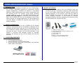
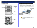
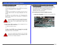
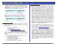
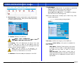
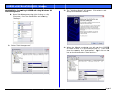
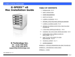
G-SPEED eS INSTALLATION GUIDE - Windows
G-SPEED™ eS
Windows
Installation Guide
TABLE OF CONTENTS
1. INTRODUCTION (Pg 4)
2. SAFETY PRECAUTIONS
3. SYSTEM REQUIREMENTS
4. WHAT’S IN THE BOX
5. G-SPEED eS OVERVIEW (Pg 5)
6. OPTIONAL G-TECH PCIe RAID CONTOLLER OVERVIEW
7. G-SPEED eS AUDIBLE ALARMS (Pg 6)
8. SETTING UP G-SPEED eS WITH THE G-TECH PCIe RAID
CONTROLLER (Pg 6)
9. SETTING UP G-SPEED eS USING THE WEB GUI (Pg 12)
10.
CONFIGURING TWO G-SPEED eS UNITS IN
RAID 5 MODE (Pg 16)
11.
WHAT TO DO IN THE EVENT OF A DISK
DRIVE FAILURE (Pg 19)
12.
TECHNICAL SUPPORT/LIMITED WARRANTY (Pg 20)
APPENDIX A – DETAILED INFORMATION ON USING THE WEB GUI
G-Technology Inc.
Tel: (310) 449-4599
Fax: (310) 449-4670
[email protected]
APPENDIX B – EXPLANATION OF RAID LEVELS
APPENDIX C – NOTES
APPENDIX D – FORMATTING G-SPEED USING DISK MANAGEMENT
P/N GSPEED eS v1.1PC
Page 1
G-SPEED eS INSTALLATION GUIDE - Windows
Page 2
G-SPEED eS INSTALLATION GUIDE - Windows
Page 3
G-SPEED eS INSTALLATION GUIDE - Windows
1. INTRODUCTION
Thank you for purchasing G-SPEED eS from G-Technology,
Inc. (G-Tech)! Specifically designed for professional content
creation applications, G-SPEED eS features a high-speed
3Gbit/sec eSATA interface and when used in conjunction with
the optional G-Tech PCI Express (PCIe) RAID controller
provides RAID 0, 1, 5, 10 and JBOD functionality with
greater than 2TB support in Windows 32bit environments.
Up to four G-SPEED eS units can be attached to the G-Tech
RAID controller for storage capacities to 16 TB and data rates
over 600 MB/sec. G-SPEED eS supports multi-stream video
editing workflows.
2. SAFETY PRECAUTIONS
The disk drives contained in your G-SPEED eS are delicate
electronic instruments and are susceptible to damage due to
excessive physical shock. Place the unit in a vented area away
from moisture or liquids. Please handle the unit with care. Do
not open the case. Doing so will void the warranty. If the
Product is returned with damage caused by improper
handling, the warranty will be void and liability will rest with
the user.
3. SYSTEM REQUIREMENTS
•
•
•
4. WHAT’S IN THE BOX
Take a moment to ensure that the following items are
included in the box. If anything is missing, please call G-Tech
at (310) 449-4599. Please keep the shipping container and
packing materials. In the unlikely event that you need to
return G-SPEED eS to us for any reason, you must use the
G-Tech shipping container. If the Product is returned
damaged caused by improper packaging, the warranty will be
void and liability will rest with the user.
•
•
•
•
•
•
•
G-SPEED eS storage system
4 removable SATA drive modules (installed in unit)
(2) disk module keys
1-meter eSATA cable
AC Power cable
Optional – G-Tech PCIe RAID controller
Configuration Utility & Installation CD
PCIe equipped workstation
Microsoft Windows 2000/XP/2003/Vista
G-Tech PCIe RAID Controller or third party port multiplier
aware eSATA host adapter
Optional G-Tech 4-port,
PCIe x4 RAID Controller
Page 4
G-SPEED eS INSTALLATION GUIDE - Windows
6. OPTIONAL G-TECH PCIe RAID CONTOLLER OVERVIEW
5. G-SPEED eS OVERVIEW
(4) Removable
Disk Drive Modules
Drive Module
Power/Activity
LED
Disk Module
Lock Hole
The optional G-Tech PCIe RAID controller connects
G-SPEED eS to your PCIe equipped workstation and
provides RAID 0, 1, 5, 10 & JBOD functionality. You will
choose your level of RAID protection when you set up
the G-SPEED eS in Section 8. For an explanation of
supported RAID levels, please refer to Appendix B.
RAID Engine
PCIe x4 interface
Power Supply
LED
Temperature/Fan RPM
Warning LED
Removable
Fan
(4) High-speed
3 Gb/s eSATA ports.
Supports up to (4)
G-SPEED eS systems
G-SPEED eS is also compatible with third-party Windows
port multiplier aware eSATA host adapters. Refer to your
host adapter documentation to set up G-SPEED eS with
these boards.
3 GB/sec
eSATA
Port
AC Input
ON/ OFF
Switch
Cable Lock
Hole
Page 5
G-SPEED eS INSTALLATION GUIDE - Windows
7. G-SPEED eS AUDIBLE ALARMS
7.1 The G-SPEED eS enclosure is equipped with an audible
alarm that sounds when:
1. The internal temperature of the G-SPEED eS enclosure
reaches a temperature of 60° centigrade
and/or
2. When the main FAN fails or the RPM of the fan slows to
a state where the fan can longer adequately cool the
system.
In addition to the audible alarm, the Temperature/Fan
Warning LED located on the front bezel of G-SPEED eS
will illuminate.
8. SETTING UP G-SPEED eS WITH THE G-TECH PCIe
RAID CONTROLLER
Connecting G-SPEED to your workstation and configuring
your system takes just a few steps as outlined below. For
this example we will be installing G-SPEED eS on a
Windows XP system. The installation is similar for
Windows 2000, 2003 and Vista.
8.1 Installing the G-Tech PCIe RAID Controller
1. Install the G-Tech RAID controller into an available PCIe
slot in your workstation.
If you hear an audible alarm and see the RED warning LED on
the front of G-SPEED eS, stop using G-SPEED eS immediately.
Check to see if the fan is spinning and move the unit to a
cooler location. If the problem persists, contact G-Tech
Support.
7.2 The G-Tech RAID controller is also equipped with an
audible alarm that sounds when:
1. A disk drive failure occurs
or
2. Secure the RAID controller in place.
2. When the G-SPEED eS is removed from the RAID
controller without first selecting “Unplug” in the Array
Maintenance menu in the web GUI.
If you hear an audible alarm coming from the G-Tech RAID
controller, see Section 11 “What to do in the Event of a Disk
Drive Failure”. See Appendix B.1.7.2 for information on the
proper way to hot “Unplug” G-SPEED eS.
Page 6
G-SPEED eS INSTALLATION GUIDE - Windows
8.2 Attaching G-SPEED eS to the G-TECH RAID Controller
1. Attach one end of the supplied eSATA cable to the eSATA
port located on the back of G-SPEED eS.
2. Attach the other end of the eSATA cable to Port 1 (port
closest to motherboard) on the G-Tech RAID controller as
shown below.
1. Install the G-SPEED eS Windows driver
a. Power on the workstation
b. Insert the G-Tech Product CD into the CD-ROM drive
When the CD loads a welcome screen may appear.
Close this window.
3. Attach the power cord to the back of G-SPEED eS and
connect the other end to AC power.
4. Power on G-SPEED eS.
8.3 Installing the G-Tech PCIe RAID Controller Software
There are three steps required to fully install the software
for the G-SPEED eS Controller.
c. When the system boots the “Found New Hardware
Wizard” will appear. Select “Install from a list or specific
location” and click <Next>.
1. Install the Windows driver
2. Update the Controller firmware
3. Installing the web GUI
Check for software updates at
http://www.g-technology.com/Support/
Page 7
G-SPEED eS INSTALLATION GUIDE - Windows
d. Select “Don’t Search, I will choose the driver
to install” and click <Next>.
f.
Click on the <Browse> Button and navigate to the CDROM drive containing the G-Tech Product CD. Continue
to “\Manuals-Drivers\G-SPEED eS\PC\GSeS Driver Winv1.0\” Select the folder for your operating system and
click <OK>.
g. Select “G-SPEED eS RAID Controller and click <Next>.
e. Click <Have Disk>.
Page 8
G-SPEED eS INSTALLATION GUIDE - Windows
h. When the Windows Logo warning screen appears
click <Continue Anyway>.
j.
i.
k. As before, click on “Don’t search. I will choose the
driver to install.”
The RAID controller driver will install and the Wizard
will complete. Click <Finish>.
A new “Found New hardware Wizard” will open for the
“G-Tech RCM device.” Click <Next>.
Page 9
G-SPEED eS INSTALLATION GUIDE - Windows
l.
Select “G-SPEED es RAID Controller” and click <Next>.
2. Update the G-SPEED eS Controller firmware
a. Insert the G-Tech Product CD into the CD-ROM / DVD
drive. When the disk loads a welcome screen should
appear. Click on the <Manuals / Drivers> link.
m. The RCM Device driver will install and the Wizard will
complete. Click <Finish>. This completes the driver
installation.
NOTE: If the Menu screen does not appear, the “autorun” feature
may not be enabled on your workstation. To load the menu
manually go to the START menu and click on “Run.” Enter the drive
letter of your CD-ROM containing the Product CD and then
“autorun.exe.” For example “D:\autorun.exe”
b. This will open Windows Explorer. Navigate to the
“G-SPEED eS\PC\GSeS Firmware-v2.2c” folder.
Double-click “hptflash.exe” to launch the flash utility.
n. Remove the G-Tech Product CD.
o. Restart your workstation.
Page 10
G-SPEED eS INSTALLATION GUIDE - Windows
c. Click <Open...>.
f.
d. Select “rr231.xpm.22c” and click <Open>.
g. Remove the G-Tech Product CD.
h. Restart your workstation.
When the process is completed click <OK>.
3. Installing the G-SPEED eS Web GUI.
a. Insert the G-Tech Product CD. When the disk loads a
welcome screen should appear. Click on the <Manuals /
Drivers> link.
e. Click <Flash!> to begin the update process.
Page 11
G-SPE
EED eS INSTA
ALLATION GUIDE - Windo
ows
b Navigate to the
b.
t
folder:
“Manuals-Drivers\G-SPEED eS\PC\GSeS WEB
W
GUI-vX.X”
e onscreen
Double click on “Setup.exe”” and follow the
instructions, accepting the defaults.
9. SET
TTING UP G-S
SPEED eS USIN
NG THE WEB GUI
G
T
The
G-Tech RAIID controller w
web GUI is used
d to configure and
a
m
monitor
the G-SPEED eS systtem. The GUI is accessed us
sing
a
any
web brow
wser such as
s Safari, Interrnet Explorer or
e
equivalent.
T
This
section w
will describe ho
ow to setup the
G
G-SPEED
eS on
n a Windows wo
orkstation.
NOTE: Windows 2000 / XP
P are 32 bit operrating systems witth a
built-in lim
mitation that logic
cal disks cannot be greater than 2TB
(2048GB).. The G-SPEED eS
S RAID Controller overcomes
o
this barrrier
w
with
a new technology, Variable Secto
or Size (VSS). VS
SS increases the se
ector
s
size
presented to th
he operating system making it possib
ble to now have log
gical
d
disks
of up to 16TB
B.
9.1 Accessing th
he G-Tech PCIe RAID Controller Web GU
UI
1 Open your web
1.
w
browser an
nd enter the folllowing address
s:
https:/
//localhost:74
402
c. When the ins
stallation is com
mplete click <Finish>.
2 The followin
2.
ng Security Ale
ert window will appear. Click the
<YES> buttton.
d. The Web GUI is ready to be
e launched and configure
ED eS.
your G-SPEE
o the G-SPEED eS Web
W
GUI
NOTE: For easy access to
save the web address in y
your favorites
Page
e 12
G-SPE
EED eS INSTA
ALLATION GUIDE - Windo
ows
3. Enter “admin
n” as the User Name
N
and “000
00” (four zeros
s)
as the Passwo
ord and click on
n the <Login> button.
4. The main scrreen of the we
eb GUI will appear as shown
n
below. Each of
o the four driv
ves in the unit are
a displayed in
n
the “Physical Device Informa
ation” section of
o the GUI.
Note: Se
ee appendix A.4.5 for instructions
s on
changing the password.
Note: The
T
G-SPEED eS is
s shipped initialized as a RAID 0 arra
ay
formatted for Mac OSX. T
This configuration needs to be delete
ed
and re
e-created to fun
nction correctly on your Window
ws
worksta
ation. Section 9.2 covers this process
s.
NOTE: Please refer to APP
PENDIX A for detailled information on the
s of the G-Tech RAID Controller web GUI.
features
Page
e 13
G-SPE
EED eS INSTA
ALLATION GUIDE - Windo
ows
9.2 C
Configuring th
he RAID level of G-SPEED eS
e
The G-SPEED eS
S/G-Tech RAID controller comb
bination can be
e
onfigured in RA
AID 0, 1, 5, 10 and JBOD. (Se
ee Appendix B
co
fo
or an explanatio
on of RAID leve
els) Follow the directions
below to setup the
t
system
3 Click the <O
3.
OK> button to p
proceed.
1. Launch the G-T
Tech RAID Controller web GUII.
2. Click on the “M
Maintenance” Liink and the win
ndow shown
below will appear. Click on <Delete>
<
in the
e Array
W
Maintenance Window.
WARNING: This will delete any data
W
sto
ored on G-SPEED e
eS!
4 The GUI will refresh and the array is no
4.
ow deleted. Click
e Array> button. The “Create
e Array” page will
the <Create
appear.
Page
e 14
G-SPE
EED eS INSTA
ALLATION GUIDE - Windo
ows
5. The Create Array page is where
w
you con
nfigure the new
ple we will setu
up
array and all itts parameters. In this examp
a RAID 0 arra
ay. (To set up
p a different RA
AID level simply
select it from the dropdown
n menu labeled
d “Array Type.””)
6.. Click the <Se
elect All> to qu
uickly select all the disks for th
he
array.
T
enter G-SPEEDeS
G
fo
or
Select RAID 0 for “Array Type”,
“Array Name”
7.. To create an array less than
n the maximum
m available,
enter the value in MB in the
e Capacity field.
8.. If you are cre
eating an array
y of Greater tha
an 2TB,
choose the value
v
for Variable Sector Size as
a
indicated in the
t
table below
w.
Arrray Capacity
Up to 2TB
NOTE: In th
his example we are creating a RAID 0 array. The
system can also
a
be set up in RAID
R
1, 5, 10 or JBO
OD mode by
selecting the
e appropriate settin
ng in the “Array Ty
ype” pull-down.
NOTE: When
n creating redundant arrays (RAID 1 or RAID 5)
the initializa
ation process takes
s time. For RAID 5 it takes
approximately 1hr 45m per TB of final capacity.
S
Sector Size
512
2TB
B -> 4TB
1k
4TB
B -> 8TB
2k
8TB
B -> 16TB
4k
NOTE: Windows 2000 / XP
P are 32 bit operrating systems
with a built-in limitation that logical disks cannot be greater
than 2TB (2048GB).
The
e G-SPEED eS RA
AID Controller
o
overcomes
this barrier with a new ttechnology, Variab
ble Sector Size
(
(VSS).
VSS incre
eases the sector s
size presented to the operating
s
system
making it possible to now hav
ve logical disks of up
u to 16TB.
Page
e 15
G-SPE
EED eS INSTA
ALLATION GUIDE - Windo
ows
9. Click <OK> on
n the warning message
m
that appears.
10. C
CONFIGURING
G TWO G-SPEE
ED eS UNITS IN
I RAID 5 MO
ODE
F
Follow
the dire
ections below to configure two G-SPEED eS
a
arrays
in RAID 5 mode using tthe G-Tech RAID controller.
1. Ensure that the G-Tech RA
AID controller is properly
nd the driver an
nd web GUI are
e loaded.
installed an
10.. Click the <Crreate> button and the arra
ay will begin to
t
initialize. A popup
p
will app
pear confirming
g the array ha
as
been
create
ed and is now initializing.
Click <OK>
>.
2. Attach both
h G-SPEED eS u
units to the G-T
Tech RAID
controller as
a shown below
w, power the un
nits and restart
your compu
uter
11.. The GUI will reload
r
indicatin
ng that the G-S
SPEED eS has
completed initializing the RAIID 0 array.
3. Launch the
e G-Tech RAID Controller web GUI. With the
two units attached
a
to the G-Tech RAID controller,
c
the GUI
G
will display
y information lik
ke that shown below.
b
NOTE: Wh
hen creating redun
ndant arrays (RAID 1 or RAID 5)
the initialization process take
es time. For RAID 5 it takes
approxima
ately 1hr 45m per TB
T of final capacity
y.
12.. Your G-SPEED
D eS is now rea
ady to be form
matted for use
with your op
perating system
m.
See App
pendix D for
detailed instructions on us
sing Disk Management to
format the G-S
SPEED eS for Windows
W
XP.
Page
e 16
G-SPE
EED eS INSTA
ALLATION GUIDE - Windo
ows
4. C
Click on the “Maintenance” link next to the array
a
with “OS
N
Name”
GS Disk
k 1_0. The window shown below will appear.
8.
Click the <Delete> button
n and the follo
owing window will
appear.
WARNING: This will delete any data
stored on G-SPEED eS.
5. C
Click the <Dele
ete> button. Th
he following window
w appear.
will
9.
<
button to delete the array. Both
Click the <OK>
arrays have
e now been de
eleted as shown below. Click
the <Creatte Array> buttton.
The “C
Create Array”
window will appear.
WARN
NING: This will dele
ete any data
stored on G-SPEED eS.
6. Click
C
the <OK>
> button to dele
ete the array.
7. R
Repeat the prrocedure for GS
G Disk 1_1.
Click on th
he
“
“Maintenance”
link next to the array with “OS Name” GS
G
D
Disk
1_1. The window below will appear.
Page
e 17
G-SPE
EED eS INSTA
ALLATION GUIDE - Windo
ows
10. In this window
w select the following values as
a shown:
Select RAID 5 for “Array Type:”,
ED-eS-R5 for “Array
“
Name:”,
Enter G-SPEE
Select Foreground for “Inittialization Method:”
ack for “Cache Policy:”
and Write Ba
Click <Select All> button to select all disks
s then click the
<Create> buttton to begin th
he initialization process.
11
1. A popup will appear confirm
ming the array has been
zing. Click <OK
K>.
created and is now initializ
12
2. The GUI will reload indicating that the G-SPEED eS is
initializing.
3. The RAID 5 initialization p
process takes approximately
a
1hr
13
45m per TB
T of final capacity.
Once the initializattion
process is complete,
c
the G
GUI will indicate
e “Type” as RA
AID
5 and “Status” as Normal.
4. Your G-SPEED eS is now ready to be formatted
f
for use
u
14
m. See Appen
ndix D for detaiiled
with your operating system
sk Managemen
nt to format the
instructions on using Dis
G-SPEED eS
S for Windows X
XP.
Page
e 18
G-SPE
EED eS INSTA
ALLATION GUIDE - Windo
ows
11. WH
HAT TO DO IN THE EVENT OF
O A DISK DRI
IVE FAILURE
Th
he G-Tech RAID controller conttinually monitors the health off
ea
ach of the disk drives
d
in G-SPE
EED eS. In the event of a disk
k
faiilure, an audible alarm will sou
und. The web GUI will also
report the failed drive and its ph
hysical position
n.
4. Remove the failed
f
drive (In
n this example
e Drive 3, of the
G-SPEED eS connected to
o port 2 of th
he G-Tech RAID
controller) by
y inserting the p
provided key in
n to the lock ho
ole
and gently slid
ding the drive m
module out of the
t
enclosure.
NOTE: If G-SPEED
G
eS was co
onfigured in a prottected RAID mode
(RAID 1, 5 or 10), a drive failure
f
does not re
esult in data loss.
However, the array is now in an unprotected sttate and the failed
drive should be replaced as so
oon as possible to avoid data loss.
ollow the steps below to identify and replace a failed drive.
Fo
1 Launch the web GUI.
1.
2 Mute the ala
2.
arm by clicking
g on the <Beepe
er Mute>
button.
3 The GUI will display information like tha
3.
at shown below
w.
ation mark on the
t
G-SPEED eS
e icon indicate
es
An exclama
that the “S
Status” of the array is Critical. The lowe
er
portion of the GUI indicates which drive in whic
ch
e unit has faile
ed.
G-SPEED eS
X
WARN
NING: Make absolutely sure that yo
ou remove the faile
ed
drive indicated by the G
GUI. If multiple G--SPEED eS units arre
conne
ected to the G-Tech RAID controller, it is a good idea to
t
follow
w the cable to ensure you know which
h Port # the array is
conne
ected to on the RAIID controller.
In this example there are two
t
G-SPEED eS un
nits connected
to the G-Tech RAID controller. Drive 3 of the G-SPEED eS
ed to Port 2 of the G-Tech RAID contrroller has failed.
connecte
REMO
OVING THE WRON
NG DRIVE WILL RESULT
R
IN THE
LOSS
S OF THE ARRAY A
AND ALL OF THE CONTENT STORE
ED
ON G-SPEED eS.
Page
e 19
G-SPE
EED eS INSTA
ALLATION GUIDE - Windo
ows
5. R
Replace the failed drive with a new disk mo
odule and securre
in place. Once the drive has spun up to spe
eed, the GUI will
ebuilding (The “Status” show
ws
indicate that the array is re
R
Rebuilding
and the percenta
age complete) as
a shown below
w.
T
The
rebuild time is approximately 2 hours pe
er TB.
6. O
Once the rebuilld is complete, G-SPEED eS is
s back to
N
Normal
and prrotecting your valuable
v
data once again.
12. TEC
CHNICAL SUPPORT
Iff you encounter
e any difficultties while installing G-SPEED
D,
pllease contact G-Tech Technical Support via
v
one of th
he
fo
ollowing ways:
Telephone:
e (310) 449-4
4599
Fax: (310
0) 449-4670
E-mail: support@g-tech
hnology.com
Internet: http://www.g--technology.com
m/support
When contacting
W
g Technical Sup
pport, make sure to be in fron
nt
off your compute
er and have the following info
ormation readily
av
vailable:
•
•
•
•
•
•
Your G-SPEED eS serial number (on bo
ottom of unit)
v
Operating system and version
Computer brand and mo
odel
ost adapter bran
nd and model
eSATA ho
Amount of
o memory installed
Other dev
vices attached to your computter
IMITED WARR
RANTY
13. LI
G
G-Technology
Inc. (G-Tech) w
warrants your Product against
a
any
defect in material and w
workmanship, under normal
u
use,
for the de
esignated warrranty period. If the Product
s
should
become
e defective w
within the warrranty period,
G
G-Tech,
will at its
i discretion, rrepair or replac
ce the Product.
R
Repair
or replacement parts o
or Products willl be furnished
o
on
an exchan
nge basis and will be either new or
r
reconditioned.
All replaced pa
arts or Products
s shall become
t
the
Property of G-Tech. This w
warranty shall not
n apply if the
P
Product
has been damaged by
y accident, mis
suse, abuse or
a a result of unauthorized service or pa
as
arts. Warranty
s
service
is availa
able to the purc
chaser by obtaining a Return
M
Material
Authorization numbe
er (RMA) and by delivering
t
the
Product du
uring the warra
anty period to an authorized
G
G-Tech
service facility or to G-Tech. The purchaser shall
b
bear
all shippiing, packing a
and insurance costs and all
o
other
costs, excluding
e
parts and labor, necessary to
e ctuate repair,
effe
p
replaceme
ent or refund
d under this
w
warranty.
All returned Prod
duct must be
e shipped to
G
G-Tech
in the original shipping
g container.
For more inform
F
mation on how
w to obtain warrranty service,
a RMA numbe
an
er or to acquire
e shipping matterials, contact
G
G-Tech
at 1653
3 Stanford Street, Santa Monica, CA 90404,
(
(310)
449-4599
9 or support@g
g-technology.co
om.
IIN THE EVENT A PRODUCT BE
ECOMES DEFEC
CTIVE DURING
T
THE
WARRANT
TY PERIOD, THE PURCHASER
R’S EXCLUSIVE
R
REMEDY
SHAL
LL BE REPAIIR OR REPLA
ACEMENT AS
P
PROVIDED
ABO
OVE. INCIDEN
NTAL OR CONS
SEPROUENTAL
D
DAMAGES,
INC
CLUDING WITH
HOUT LIMITATIION LOSS OF
D
DATA,
ARISING
G FROM BREA
ACH OF ANY EXPRESS OR
I
IMPLIED
WARRANTY ARE NOT
T THE RESPONS
SIBILITY OF GT
TECH
AND, TO
O THE EXTENT
T PERMITTED BY LAW, ARE
H
HEREBY
EXCLU
UDED BOTH FO
OR PROPERTY DAMAGE,
D
AND
T THE EXTENT
TO
T NOT UNCONSCIONABLE, FO
OR PERSONAL
I
INJURY
DAMAG
GE.
Page
e 20
G-SPE
EED eS INSTA
ALLATION GUIDE - Windo
ows
APPE
ENDIX A: WEB
B GUI
1 Manage:
1.
s is the main screen of the G-SPEED eS
Array: This
web GUI. G-SPEED
G
eS is configured an
nd monitored
from this pa
age. (See Appe
endix A.1 for de
etails)
Devices: Hard
H
drive param
meters are mod
dified on this
page (you should not make
m
any chan
nges on this
t
drives are
e configured for optimal
page as the
performance with the G-SP
PEED eS.
ol: When conffigured in prottected mode
Spare Poo
drives can be
b assigned to a “spare pool”” (sometimes
called hot spare).
s
These drives
d
will be automatically
a
added to the Array in the event
e
of a drive
e failure.
2 Events: All events of the G-SPEED eS controller
2.
c
are
ere, such as array
a
changes and failures.
recorded he
These even
nts can be em
mailed by settin
ng up email
notification under the “Setttings” tab.
3 Tasks: Schedule the G-Tech controller to
3.
o
t
of the RAID
R
automatically verify the integrity
volume.
A.1 Manage: Array
A
A
name (as shown in GUI only).
1. Name: Array
vel of array.
2. Type: Displays RAID lev
y: you guessed it… capacity off the array.
3. Capacity
P
Displays current write
e cache policy
4. Cache Policy:
for RAID
D protected a
arrays. For more
m
info see
appendix
x B.1.7.7
me: Controllerr assigned na
ame that will
5. OS Nam
display in
n Disk Utility.
D
curren
nt status of arra
ay.
6. Status: Displays
Norma
al: All systems go
Critica
al: Drive failure
e has occurred
Initiallizing: Building
g RAID 1, 5 or 10 array
Rebuiilding: Parity data being recon
nstructed
4 Settings: Configure the
4.
e G-SPEED eS controller
settings such as login password and email
x A.4 for details
s
notification.. See Appendix
5 Drive Stattus: Check the status of all connected
5.
hard drives including detaiiled SMART datta.
6 Logout: Sa
6.
ay goodbye
Page
e 21
G-SPE
EED eS INSTA
ALLATION GUIDE - Windo
ows
7.4 OCE/ORL
LM:
Online Capacity Expansio
on: It is possible to expand th
he
o an existing arrray when additional
capacity of
G-SPEED eS
e units are ad
dded to the systtem.
Online RA
AID Level Migra
ation: it is poss
sible to change
the RAID level of an exis
sting array.
e: Displays configuration and maintenance
7. Maintenance
options for cu
urrent array. Th
he options diffe
er depending
on RAID levell of the array.
RAID 0
e devices curre
ently part of the
t
Array, theirr
7.5 Shows the
location an
nd status.
“Devic
ce_Controller
r#_Port#_Driv
ve#”
RAID 5
D
currentt Array
7.1 Delete: Deletes
NING: THIS OPERATION WILL DELET
TE
WARN
THE ARRAY
A
AND AL
LL DATA ON IT!!
sconnect the Array
A
from th
he
7.2 Unplug: This will dis
B sure to clo
ose all files be
efore using this
controller. Be
option. This enables the arrays to be unplugged from th
he
a
system without causing an alarm.
NOTE: While the conttroller is “hot pluggable,”
p
we
recomm
mend shutting the system down when connecting or
disconne
ecting G-SPEED eS
S from the controlle
er.
ay as displayed in the GUI.
7.3 Rename: Renames arra
7.6 Verify: Ve
erifies the integ
grity of the RAID
D set.
C
Policy: This option is available for
7.7 Change Cache
RAID 5 arrays..
Write-b
back: (Defaultt) Data written to the array
is cache
ed. This will res
sult in higher performance,
p
but datta loss may o
occur in case of a power
failure.
Write-tthrough: Data written to the
t
array is
always passed directly
y to the disks. Subsequent
reads may
m
still be com
mpleted from the
t
cache, if
approprriate
Page
e 22
G-SPE
EED eS INSTA
ALLATION GUIDE - Windo
ows
8.1 Array Type
e: select the RA
AID level for new
w array
8.2 Array Nam
me: This is the name that wiill be displayed
d in
the MAIN pa
age of the GUI.
8.3 Initializatio
on Method: Se
ets the priority of the RAID
creation pro
ocess.
Create Array
8. C
C
Click
on “Create Array” and the
e following will appear.
Foregrou
und: All controlller resources are
a used for th
he
creation process
p
and th
he array is nott available unttil
complete.
Backgrou
und: Minimal controller reso
ources are use
ed
for the cre
eation process and the array
y is available fo
or
immediate
e use.
NOT
TE: RAID protection is not available
until initialization is complete
8.4 Cache Polic
cy: This option
n is available when creating
a RAID 5 arrray.
Write-back: Data written tto the array is cached. This
n higher performance, but da
ata loss may
will result in
occur in case
e of a power faiilure.
Write-throu
ugh: Data writtten to the arra
ay is always
passed direc
ctly to the disk
ks. Subsequentt reads may
still be completed from the cache, if appro
opriate
8.5 Select All: Simple method
d to select all diisks.
8.6 Available Disks:
D
Display
ys disks curren
ntly available
for array creation,
c
showiing location, drive
d
model,
serial numb
ber, size of th
he disk and current
c
free
capacity.
#/Port#/Drive
e#”
Location: “Controller#
D
Enter tthe desired cap
pacity of the
8.7 Available Disks:
new array.
Default is
s the Maximu
um capacity
available.
8.8 Create: As
s expected, se
electing this wiill begin the
array creatio
on process.
Page
e 23
G-SPE
EED eS INSTA
ALLATION GUIDE - Windo
ows
ocation: Show
ws the location of
o disks attache
ed to the
9. Lo
controller.
Lo
ocation: “Contr
roller#/Port#/
/Drive#”
10. Mo
odel: Displays
s the drive mo
odel and serial number of
dis
sks currently atttached to the controller.
c
(This page left inte
entionally blan
nk)
11. Ca
apacity: Displa
ays the advertised capacity of
o the disks
currently attache
ed to the contro
oller.
12. Ma
ax Free: Displays the maxim
mum free capa
acity of the
dis
sks currently atttached to the controller.
c
13. Re
escan: Rescan
ns the eSATA bus to detectt any new
de
evices attached.
14. Be
eeper Mute: Mutes
M
audible be
eeper.
NOTE: Beepe
er will sound when a drive fails or an array
a
is
disconnected from the system without
w
first selectin
ng
“Unplug” in th
he Array Maintenan
nce menu.
Page
e 24
G-SPE
EED eS INSTA
ALLATION GUIDE - Windo
ows
Appendix A.4: Settings
1. Auto Rebuild
d: Enables orr disables the auto-rebuild
feature. Whe
en enabled, a critical RAID 5 or RAID 1
array will auttomatically reb
build when a new
n
drive is
inserted. See
e Section 12 forr details.
2. Audible Alarrm: Enables orr disables the audible alarm
3. Rebuild Prio
ority: Sets the
e amount of co
ontroller CPU
time dedicate
ed to rebuilding
g an array. Higher Priority
will rebuild th
he array faster, however the array
a
will be
less responsiv
ve to the system
m.
s feature is not currently suppo
orted.
4. SAF-TE: This
ort: The port used to connect to the
5. Listening Po
G-SPEED web
b GUI. “Restric
ct to local acce
ess” disables
network users
s to access the GUI. Default is
i Port 7402.
C
login p
password. Defau
ult is 0000
6. Password: Changes
7. SMTP Settin
ng: Email serrver informatio
on necessary
for email nottification. Ente
er your server information
here.
nts.
8. Recipients: A list of currentt email recipien
ent: Add em
mail addresses
s for email
9. Add Recipie
notification. Select
S
Event lev
vel to trigger an email.
Information: Informational events are sent
arning events a
are sent
Warning: Wa
Error: Error events
e
are sentt
nt
Test: Sends a test email to the new accoun
0.HDD Temperrature Thresh
hold: Adjusts the threshold
10
of the hard drive temperature to trigger a warning
ult is 50°C, ho
owever today’s
s disk drives
email. Defau
can operate up
u to 60°C.
Page
e 25
G-SPEED eS INSTALLATION GUIDE - Windows
APPENDIX B: RAID levels explained
RAID
Level
0
1
5
Description
Disk striping
Mirroring
Disk striping
with
distributed
parity
Advantage
Offers the highest
performance and a
useable storage
capacity of 100%
of total available
storage capacity
Maximum level of
data protection as
identical data is
written to multiple
drives
High read
performance,
medium write
performance with
data protection in
case of a drive
failure.
APPENDIX C: Notes
Disadvantage
No fault tolerance failure of one drive
in the array results
in complete data
loss
Ideal For…
Content creation
applications
requiring highest
storage capacity
Useable storage
space is 50% of
total available
capacity
Applications in
which data
security is
paramount
Useable storage
capacity equals
total capacity of all
drives in the array
less the capacity of
one drive.
Content creation
applications
requiring data
protection
When the G-Tech web GUI is open dropped frames
may occur in editing applications such as Final Cut
Pro and Premiere Pro. We recommend not having the
GUI open while working in these programs.
It is recommended not to exceed the standard eSATA
cable length of 1 meter (3 feet).
Up to (4) G-SPEED eS storage units can be attached
to the G-Tech RAID controller for up to 16TB of
capacity and over 600 MB/sec of performance.
Replacements / extra G-SPEED eS disk modules are
available for purchase online at:
www.g-technology.com/products/g-speed-es.cfm
For example, a 4x
1TB RAID 5 yields
a useable capacity
of 3 TB.
10
JBOD
Mirror of
striped drive
pairs
Just-abunch-ofdisks
Higher
performance than
RAID 1 with same
level of data
protection.
Each drive can be
accessed as an
individual volume.
Useable storage
capacity is 100%
of total available
storage.
Disk failure results
in slight drop in
performance
Useable storage
space is 50% of
total available
capacity
No fault tolerance
Content creation
applications
requiring data
protection
Audio
applications
Page 26
G-SPE
EED eS INSTA
ALLATION GUIDE - Windo
ows
APPENDIX D: Forma
atting G-SPEED
D eS using Windows XP
anagement
Disk Ma
3.. The “Initialize Wizard” will a
appear. Click <Next>
<
and
e default values
s.
accept all the
1 Open Disk Management
1.
M
by
y right clicking on <My
Computer> from the Startt Menu and sele
ecting
“Manage.”
2. Select “Disk Management”
4.. When the Wizard
W
complete
es you will see
e the G-SPEED
D
eS listed as Disk X (in this example Disk 1). It will also
o
pacity and “Unallocated.” Rig
ght click on the
e
show the cap
bar as shown
n and select “New Partition.”
Page
e 27
G-SPEED eS INSTALLATION GUIDE - Windows
5. The “New Partition Wizard” will open, click <Next>.
(This page left intentionally blank)
6. Follow the prompts, accepting the default values. When
you reach this screen, enter the values as shown.
Select “Perform a quick format” and then click <Next>.
7. The Wizard will complete and bring you back to the Main
Disk Management screen. The G-SPEED eS will format in
just a few seconds and be ready to use!
Pag
Pa
ge 28