1
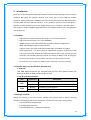
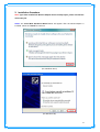
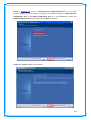
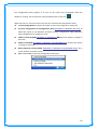
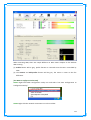
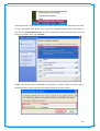
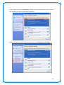
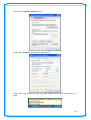
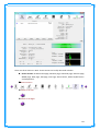
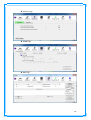
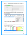
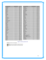
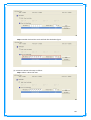
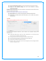
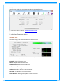
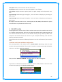
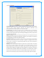
IEEE 802.11n
Wireless LAN PCI Adapter
User’s Manual
October 2010
FCC Warning
This equipment has been tested and found to comply with the limits for a Class C digital
device, pursuant to part 15 of the FCC Rules. These limits are designed to provide reasonable
protection against harmful interference in a residential installation. This equipment
generates, uses, and can radiate radio frequency energy and, if not installed and used in
accordance with the instructions, may cause harmful interference to radio communication.
However, there is no guarantee that interference will not occur in a particular installation. If
this equipment does cause harmful interference to radio or television reception, which can
be determined by turning the equipment off and on, the user is encouraged to try to correct
the interference by one or more of the following measures:
- Reorient or relocate the receiving antenna.
- Increase the separation between the equipment and receiver.
- Connect the equipment into an outlet on a circuit different from that to which
- Consult the dealer or an experienced radio/TV technician for help. the receiver is
connected.
FCC Caution: Any changes or modifications not expressly approved by the party responsible
for compliance could void the user’s authority to operate this equipment.
This device complies with Part 15 of the FCC Rules. Operation is subject to the following two
conditions: (1) This device may not cause harmful interference, and (2) this device must
accept any interference received, including interference that may cause undesired
operation.
NOTE: All Telecom and safety Tests only include this content hardware device only.
IMPORTANT NOTE:
FCC Radiation Exposure Statement:
This equipment complies with FCC radiation exposure limits set forth for an uncontrolled
environment. This equipment should be installed and operated with a minimum distance of
about eight inches (20cm) between the radiator and your body.
This transmitter must not be co-located or operated in conjunction with any other antenna
or transmitter.
Modular Approval Statement:
This device is intended to be used only for OEM integrator under the following conditions:
1) The antenna must be installed such that 20 cm is maintained between the antenna and
users, and
2) The transmitter module may not be co-located with any other transmitter or antenna.
1
IMPORTANT NOTE:
In the event that these conditions cannot be met (for example certain laptop configurations
or co-location with another transmitter), then the FCC authorization is no longer considered
valid and the FCC ID cannot be used on the final product. In these circumstances, the OEM
integrator will be responsible for re-evaluating the end product (including the transmitter)
and obtaining a separate FCC authorization.
Revision History
Revision
History
V1.0
1st release
All brand and product names mentioned in this manual are trademarks and/or registered
trademarks of their respective holders.
2
Contents
1. Introduction ...........................................................................4
1.1 Features ................................................................................................. 4
1.2 Familiar with your new wireless network card ........................................ 4
1.3 Package Contents ................................................................................... 4
1.4 Before you start...................................................................................... 5
1.5 Hardware Installation ............................................................................. 5
2. Installation Procedure ...............................................................7
3. Wireless Network Configuration Utility ........................................ 13
3.1 RaUI Wireless Utility & Windows Zero Configuration (WZC) ...................13
3.2 Start RaUI Utility....................................................................................18
3.3 Profile ...................................................................................................25
3.3.1 Add/Edit Profile .........................................................................26
3.3.2 Example to Add Profile in Profile ................................................27
3.4 Network ................................................................................................29
3.5 Advanced ..............................................................................................31
3.6 Statistics ................................................................................................33
3.7 WMM ....................................................................................................34
3.8 WPS ......................................................................................................40
3.9 SSO .......................................................................................................43
3.10 CCX......................................................................................................44
3.11 About ..................................................................................................45
3.12 Link Status ...........................................................................................45
4. Soft-AP Function.................................................................... 46
4.1 Switch to AP mode and Basic Configuration ...........................................46
4.2 Security Settings ....................................................................................49
4.3 Access Control .......................................................................................50
4.4 MAC Table .............................................................................................51
4.5 Event Log...............................................................................................51
4.6 Statistics ................................................................................................52
4.7 About ....................................................................................................53
3
1. Introduction
Thank you for purchasing this high-speed wireless network card! Excepting common wireless
standards 802.11b/g, this wireless network card is also able to access 802.11n wireless
networks - data transfer rate is 300Mbps, and that’s three times faster than 802.11g wireless
network! With easy-to-install PCI interface - a very common expansion port of computers plug this wireless network card into any empty PCI slot of your computer, just that simple!
This product is made in ISO9001 approved factory and complies with FCC part 15 regulations
and CE approval.
1.1 Features
‧ High-efficiency antenna expands the scope of your wireless network.
‧ High-speed data transfer rate - Up to 300Mbps.
‧ WMM function: control the bandwidth required for different applications.
‧ Work with IEEE 802.11b/g/n wireless devices.
‧ Supports major encryption methods like WEP, WPA, and WPA2 encryption.
‧ WPS configuration - You don’t need an experienced computer technician to help
you to get connected. Utilizing the software program of the card, you can get your
computer connected by pushing a button or entering an 8-digit code. Pressing the
button on the network card, the WPS connection can be activated as well.
‧ PCI interface - you can get it installed on your computer in just few seconds!
1.2 Familiar with your new wireless network card
1. Antennas
Two 2dBi dipole antennas are enclosed with the PCI card. Please secure the
antenna to Reverse SMA connector of the card.
2. Link & Tx/Rx LED Definitions
LED
Light Status
Link
Tx/Rx
Description
On
Link to a wireless access point
Off
Radio is switched to off
Blinking
Off
Transferring / receiving data
No wireless activity
1.3 Package Contents
Before you starting to use this wireless network card, please check if there’s anything
missing in the package, and contact your dealer of purchase to claim for missing items:
‧ One PCI Wireless Network Card
‧ Two 2dBi Dipole Antennas
‧ One CD-ROM (Drivers / Utility/User Manual)
4
1.4 Before you start
You must have the requirements as follow,
‧ A computer with an available PCI slot
‧ At least a 300MHz processor and 32MB memory
‧ Windows 2000/XP/Vista or Windows 7 operation system
‧ A CD-ROM drive
‧ At least 100MB of available disk space.
‧ Wireless PCI Adapter properly installed
1.5 Hardware Installation
STEP1: Turn off your computer and remove its cover
STEP2: Insert the PCI wireless network card into an available PCI slot firmly. Please refer to
the illustration below:
5
STEP3: Secure this card to the rear of the computer chassis and replace the cover.
STEP4: Install the antenna on the wireless network card, and make sure the antenna is
securely installed. To improve radio reception, please adjust antenna to the proper position.
STEP5: Turn on the computer.
6
2. Installation Procedure
Note: If you have installed the Wireless Adapter driver & utility before, please uninstall the
old version first.
STEP1: The Found New Hardware Wizard below will appear after the WLAN adapter is
installed. Please click Cancel to continue.
(For Windows Vista)
(For Windows XP)
7
(For Windows 2000)
STEP2: Insert Installation CD into CD-ROM drive, windows below will appear. Click Install
Driver & Utility to begin device driver installation.
8
STEP3: Please read the following license agreement. Use the scroll bar to view the rest of
this agreement. Select I accept the terms of the license agreement and click Next to
continue.
STEP4: Choose Install driver and Ralink WLAN Utility and click Next to continue.
9
STEP5: In Windows XP, there is a Windows Zero Configuration Tool for you to setup
wireless adapter. You can choose to configure the adapter through the Microsoft Zero
Configuration Tool or the Ralink Configuration Tool. It is recommended to choose the
Ralink Configuration Tool for the adapter. Click Next to continue.
STEP6: Click Install to begin the installation.
10
STEP7: Please wait for a while during the Wireless LAN adapter is configuring your new
software installation.
STEP8: After the setup wizard has successfully installed wireless LAN, click Finish to exit the
wizard.
11
The Configuration Utility appears as an icon on the system tray of Windows while the
adapter is running. You can open the utility by double-click on the icon.
Right-click the icon, there are some items for you to operate the configuration utility,
Launch Config Utilities Select this option to open the Configuration Utility tool.
Use Zero Configuration as Configuration utility (Available on Windows XP only) Select this option to use Windows XP built-in wireless configuration utility (Windows
Zero Configuration) to configure to card.
Switch to STA+AP Mode (Available on Windows 7) Select this option to change to
AP mode.
Switch to AP Mode (Available on Windows Vista/XP/2000 only) Select this option
to change to AP mode.
Open Diagnostic Testing Mode (Available on Windows Vista/XP/2000 only) To
check network connection status.
Exit Select Exit to close the Configuration Utility tool.
12
3. Wireless Network Configuration Utility
3.1 RaUI Wireless Utility & Windows Zero Configuration (WZC)
The Configuration Utility is a powerful application that helps you to configure the Wireless
LAN adapter and monitor the link status and statistics during the communication process.
When the adapter is installed, the configuration utility will be displayed automatically. This
adapter will auto connect to wireless device which has better signal strength and no wireless
security setting.
In Windows XP, it provides wireless configuration utility named “Windows Zero
configuration” which provides basic configuration function for Ralink Wireless NIC, Ralink’s
Utility (RaUI) provides WPA supplicant functionality. To make it easier for user to select the
correct utility, RaUI will let user make the selection when it first runs after windows XP
boots.
RaUI can co-exist with WZC (Windows Zero Configuration). When coexisting with WZC, RaUI
only provides monitoring function, such as link status, network status, statistic counters,
advance feature status, WMM status and WPS status. It won’t interfere with WZC’s
configuration or profile functions. Please see below picture: To select WZC or RaUI
If “Use Zero Configurations as Configuration utility” is selected, please continue on the
section. Below picture shows that the RaUI status when WZC is active as main control utility.
13
When activating WZC, there are couple different on RaUI status compare to the without
WZC running:
(1) Profile button will be gray, profile function is removed since the NIC is controlled by
WZC.
(2) The connect and add profile function will be gray. The reason is same as the first
difference.
[Use WZC to configure wireless NIC]
STEP1: Right-click Ralink configuration utility icon and select “Use Zero Configuration as
Configuration Utility”.
STEP2: Right-click the network connection icon in the task bar.
14
STEP3: All wireless access point in proximity will be display here. If the access point you want
to use is not display here, please try to move your computer closer to the access point, or
you can click “Refresh Network List” to rescan access points. Click the access point you wan
to use if it’s shown, then click “Connect”.
STEP4: If the access point is protected by encryption, you have to input its security key or
passphrase here. It must match the encryption setting on the access point.
15
STEP5: When you see the “Connected” message, the connection between your computer
and wireless access point is successfully established.
STEP6: If you want to modify information about AP, click “Change advanced settings”
16
STEP7: Choose “Wireless Networks” tab.
STEP8: Click “Properties” and then click “OK” button.
STEP9: After filling appropriate value, click “OK” button. And the status will prompt up as
below.
17
STEP10: Click the Ralink’s icon will bring up RaUI main window. User can find the
surrounding APs in the list. The current connected AP will also show with the green icon
indicated as below screen. User may user the available tab to configure more advanced
features provided by Ralink’s wireless NIC.
3.2 Start RaUI Utility
When starting RaUI, system will connect to the AP with best signal strength without setting
profile or matching profile setting. It will issue a scan command to wireless NIC. After two
seconds, the AP list will updated with the result of BSS list scan. The AP list include most
used fields, such as SSID, network type, channel used, wireless mode, security status and
signal percentage. The arrow icon indicates the connected BSS or IBSS network.
18
There are three sections in RaUI. These sections are briefly described as below.
Button Section: Include Profile page, Network page, Advanced page, Statistics page,
WMM page, WPS page, SSO page, CCX Page, About button, Radio On/Off button
and Help button.
Button Section
Move to the Left
Move to the Right
19
Function Section: Corresponding button
Profile Page
Network Page
Advanced Page
20
Statistics Page
WMM Page
WPS Page
21
SSO Page (available on Windows XP & 2000 OS)
CCX Page (available on Windows Vista, XP & 2000 OS)
About Page
22
Status Section: Include Link Status, Authentication Status, AP’s information,
Configuration and retrying the connection when authentication is failed.
Link Status
Authentication Status
AP’s Information
23
Retry the Connection
Configuration
At the mean time of starting RaUI, there is also a small Ralink icon appears within
windows taskbar as below. You may double click it to bring up the main menu if
you selected to close RaUI menu earlier. You may also use mouse;s right button to
close RaUI utility.
Ralink icon in system tray.
Besides, the small icon will change color to reflect current wireless network
connection status. The status indicates as follow:
-- indicate Connected and Signal Strength is Good.
-- indicate Connected and Signal Strength is Normal
-- indicate Wireless NIC is not connected yet
-- indicate Wireless NIC is not detected
-- indicate Connected and Signal Strength is Weak
24
3.3 Profile
Profile can book keeping your favorite wireless setting among your home, office, and other
public hot-spot. You may save multiple profiles, and activate the correct one at your
preference.
[Definition of each field]
Profile Name: Name of profile, preset to PROF﹡(﹡indicate 1,2,3,…)
SSID: AP or Ad-Hoc name
Network Type: Network’s type, including infrastructure and Ad-Hoc.
Authentication: Authentication mode
Encryption: Encryption Type
Use 802.1x: Whether or not use 802.1x feature
Tx Power: Transmit power, the amount of power used by a radio transceiver to send the
signal out.
Channel: channel in use for Ad-Hoc mode
Power Save Mode: Choose from CAM (Constantly Awake Mode) or Power Saving Mode.
RTS Threshold: User can adjust the RTS threshold number by sliding the bar or key in the
value directly.
Fragment Threshold: User can adjust the Fragment threshold number by sliding the bar or
key in the value directly.
[Icons and buttons]
indicate connection is successful on currently activated profile
indicate connection is failed on currently activate profile
indicate network type is infrastructure mode
indicate network type is Ad-Hoc
indicate security-enabled wireless network
Add a new profile
Edit an existing profile
25
Delete an existing profile
Activate selected profile
Show the information of Status Section
Hide the information of Status Section
3.3.1 Add/Edit Profile
There are 3 methods to open Profile Editor form:
You can open it from “Add to Profile” button in Site Survey function
You can open it form “Add” button in Profile function
You can open it from “Edit” button in Profile function
Profile Name: User can chose name for this profile, or use default name defined by system.
SSID: User can key in the intended SSID name or use pull down menu to select from
available APs.
Power Save Mode: Choose from CAM [Constantly Awake Mode] or Power Saving Mode.
Network Type: There are two types, infrastructure and 802.11 Ad-Hoc mode. Under Ad-Hoc
mode, user can also choose the preamble type, the available preamble type includes auto
and long. In addition to that the channel field will be available for setup in Ad-Hoc mode.
Tx Power: You can select the wireless output power here. If you’re not too far from AP (good
26
signal reception), you can select a lower output power to save energy; for a distant access
point, you can select a higher output power. It’s suggested to select “Auto” to let setup
utility decide the best output power for you.
Preamble: Select the preamble for Ad hoc mode here. Available option are “Auto” and
“Long”.
RTS Threshold: User can adjust the RTS threshold number by sliding the bar or key in the
value directly. The default value is 2347.
Fragment Threshold: User can adjust the Fragment threshold number by sliding the bar or
key in the value directly. The default value is 2346.
Channel: Only available for setting under Ad-Hoc mode. User can choose the channel
frequency to start their Ad-Hoc network.
Authentication Type: There are 7 type of authentication modes supported by RaUI. They are
Open, Shared, LEAP, WPA, WPA-PSK, WPA2, WPA2-PSK.
Encryption Type: For open and shared authentication mode, the selection of encryption
type are None and WEP. For WPA, WPA2, WPA-PSK and WPA2-PSK authentication mode,
the encryption type supports both TKIP and AES.
802.1x Setting: It is an authentication for WPA and WPA2 certificate to server.
WPA Pre-Shared Key: This is the shared secret between AP and STA. For WPA-PSK and
WPA2-PSK authentication mode, this field must be filled with character longer than 8 and
less than 32 lengths.
WEP Key: Only valid when using WEP encryption algorithm. The key must matched AP’s key.
There are several formats to enter the keys:
Hexadecimal – 40bits: 10 Hex characters
Hexadecimal – 128bits: 26 Hex characters.
ASCII – 40bits: 5 ASCII characters
ASCII – 128bits: 13 ASCII characters
Show Password: Check this box and all passphrases or security keys you inputted will be
displayed as you type, but not replace your input with asterisk.
Use 802.1x: If the access point you wish to connect requires 802.1x authentication, please
click on ‘Use 802.1x’ box, then click ‘802.1X’ tab to set 802.1x parameters.
3.3.2 Example to Add Profile in Profile
Step 1: Click Add in Profile function
27
Step 2: Add Profile page will pop up.
Step 3: Change profile name to what you want to connect. Pull down the SSID and select one
intended AP. The AP list is the result of last Network.
28
Step 4: To set authentication/encryption information for the access point, please click
“Auth.\Encry.” Tab.
Step 5: Then, you can see the profile which you set appear in the profile list. Click “Activate”
to activate the profile setting.
3.4 Network
Under the Network function, system will display the information of surrounding APs from
last scan result. List information includes SSID, BSSID, Signal, Channel, Encryption algorithm,
Authentication and Network type as below:
29
[Definition of each field]
Sorted by >>: You can decide how to sort all listed access point by SSID, Channel, Signal
(Signal strength).
Show dBm: Check this box to show the signal strength of access point, instead of
percentage.
Rescan: Click this button to rescan access points. You can click this button for several times,
if the access point you wish to use does not show in the list.
Add to Profile: You can store a specific access point to profile, so you can link to that access
point directly next time without inputting authentication key again.
Connect: Connect to a selected access point. You have to select an access point from the list
first and then click “Connect” to connect to the selected access point.
[Icons & Buttons]
Indicate connection is successful.
Indicate network type is infrastructure mode.
Indicate network type is Ad-Hoc mode.
Indicate security-enabled wireless network.
Indicate 802.11a wireless mode
Indicate 802.11b wireless mode.
Indicate 802.11g wireless mode.
Indicate 802.11n wireless mode.
Indicate the
AP lists are sorted by SSID, Channel, or Signal.
Command to connect to the selected network.
Issue a rescan command to wireless NIC to update information on
surrounding wireless network.
Add the selected AP to Profile setting. It will bring up profile page and
save user’s setting to a new profile.
[Connected Network]
(1) When RaUI first ran, it will select the best AP to connect automatically.
30
(2) If user wants to connect to other AP, He can click “Connect: button for the intended AP
to make connection.
(3) If the intended network has encryption other than “Not Use”, RaUI will bring up the
security page appropriate information to make the connection.
(4) When you double-click on the intended AP, you can see AP’s detail information.
3.5 Advanced
This wireless network card provides several advanced settings for experienced wireless users.
You can change these settings to increase data transfer performance, or change operation
mode.
Wireless Mode: Select wireless mode. Support 2.4G only.
Enable Tx Burst: Ralink’s proprietary frame burst mode.
Enable TCP Windows Size: Enhance throughout.
Fast Roaming at: Fast to roaming, setup by transmit power.
Select your Country Region Code: The available channel differs from different countries.
For example: USA (FCC) is channel 1-11, Europe (ETSI) is channel 1-13. The operating
frequency channel will be restricted to the country user located before importing. If you are
in different country, you have to adjust the channel setting to comply the regulation of the
country. Supporting region code for this section has CH1-11, CH1-13, CH10-11, CH10-13,
CH14, CH1-14, CH3-9, and CH5-13. Please refer to below Channel Classification and range,
Country Channel list to select your Country Region Code:
Figure 1: Channel Classification and range
31
Figure 2: Country Channel list
Apply: Save the save changes
Show the information of Status Section
Hide the information of Status Section
32
3.6 Statistics
The configuration utility provides information about network statistics and link status. If you
want to know how your wireless network card works, you can use these functions to get
detailed information about the wireless connection you’re using.
[Transmit Statistics]
Frames Transmitted Successfully: Frames successfully sent.
Frames Retransmitted Successfully: Successfully retransmitted frames numbers
Frames Fail To Receive ACK After All Retries: Frames failed transmit after hitting retry limit.
Reset Counter: Reset counters to zero
[Receive Statistics]
Frames Received Successfully: Frames received successfully.
Frames Received With CRC Error: Frames receive with CRC error.
Frames Dropped Due To Out-Of-Resource: Frames dropped due to resource issue.
Duplicate Frames Received: Duplicate received frames.
Reset Counter: Reset counters to zero
Show the information of Status Section
Hide the information of Status Section
All connection-related statistics is displayed here. You can click ‘Transmit’ or ‘Receive’ tab,
to view the statistics of transmitted or received packets. You can also click ‘Reset Counter’
button, to reset the statistics of all items back to 0.
33
3.7 WMM
This wireless network card provides WMM (Wi-Fi Multimedia) function, which can improve
the performance of certain network applications, like audio/video streaming, network
telephony (VoIP), and others. When you enable the WMM function of this network card, you
can define the priority of different kinds of data, to give higher priority to applications which
require instant responding. Therefore you can improve the performance of such network
applications.
WMM Enable: Check this box to enable WMM function. Please click ‘Apply’ button on the
right of this check box after you check or uncheck this box, so corresponding settings in this
window will be activated or deactivated respectively.
WMM-Power Save Enable: Check this box to enable WMM power saving mode to save
energy, and let your computer’s battery live longer. You also have to select WMM power
save modes here:
AC_BE: Best Performance
AC_BK: Worst Performance
AC_VI: Video data has priority
AC_VO: Voice data has priority
Direct Link Setup Enable: If you have another WMM-enabled wireless device, you can enter
its MAC address here, then click ‘Apply’ button, and this network card will establish a direct
link to the wireless device you specified here.
You also have to specify the timeout value of this directly-linked wireless device. Valid values
are from 1 to 65535 (seconds), and input ‘0’ for infinity.
If you want to remove a specific wireless device from direct link table, select the device and
click this button to remove it.
[WMM Enable – Enable Wi-Fi Multi-Media]
If you want to use “WMM-Power Save” or “Direct Link Setup” you must enable WMM. The
setting methods of enabling WMM indicating as follow:
Step 1: Click “WMM Enable”
34
Step 2: Change to “Network” function. And add an AP that supports WMM features to a
Profile. The result will look like the below figure in Profile page.
[WMM-Power Save Enable – Enable WMM Power Save]
Step 1: Click “WMM-Power Save Enable”
35
Step 2: Please select which ACs you want to enable. The setting of enabling WMM-Power
Save is successfully.
[Direct Link Setup Enable – Enable DLS (Direct Link Setup)]
Step 1: Click “Direct Link Setup Enable”
Step 2: Change to “Network” function. And add an AP that supports DLS features to a Profile.
The result will look like the below figure in Profile page.
36
The Setting of DLS indicates as follow:
(1) Fill in the blanks of Direct Link with MAC address of STA. The STA must conform to 2
conditions as follow:
Connect with the same AP that support DLS features.
Have to enable DLS
37
(2) Timeout Value represent that it disconnect automatically after some seconds. The value
is integer. The integer must be between 0~65535. It represents that it always connects if
the value is zero. Default value of Timeout Value is 60 seconds.
(3) Click “Apply” button. The result will look like the below figure.
Describe “DLS Status” as follow:
(1) As the up figure, after configuring DLS successfully, show MAC address of the opposite
side and Timeout Value of setting in “DLS Status”. In “DLS Status” of the opposite side, it
shows MAC address of itself and Timeout Value of setting.
(2) Display the values of “DLS Status” to “Direct Link Setup” as follow:
Step 1: In “DLS Status”, select a direct link STA what you want to show its values in
“Direct Link Setup”.
38
Step 2: Double-Click and the result will look like the below figure.
(3) Disconnect Direct Link Setup as follow:
Step 1: Select a direct link STA.
39
Step 2: Click “Tear Down” button. The result will look like the below figure.
3.8 WPS
Wi-Fi Protected Setup (WPS) is the latest wireless network technology which makes wireless
network setup become very simple. If you have WPS-enabled wireless access point, and you
want to establish a secure connection to it, you don’t have to configure the wireless access
point and setup data encryption by yourself. All you have to do is to go to the WPS setup
page of this wireless card, click a button, and then press a specific button or enter a set of
8-digit code on the wireless access point you wish to establish a secure connection - just
three simple steps!
For older wireless access points, it’s possible to perform a firmware upgrade to become a
WPS-enabled access point. Since they may not have a hardware button to press for WPS
setup, you can use an alternative WPS setup method - input the pin code. Every
WPS-compatible wireless network card support pin code configuration method; you can just
input the code to wireless access point, and the wireless access point and wireless network
card will do the rest for you.
This wireless network card is compatible with WPS. To use this function, the wireless access
point you wish to connect to must support WPS function too. Now, please follow the
following instructions to establish secure connection between WPS-enabled wireless access
point and your wireless network card.
40
WPS Configuration: The primary goal of Wi-Fi Protected Setup (Wi-Fi Simple Configuration)
is to simply the security setup and management of Wi-Fi networks. Ralink STA as an Enrollee
or external Registrar supports the configuration setup using PIN configuration method or
PBC configuration setup using PIN configuration method or PBC configuration method
through an internal or external Registrar.
WPS AP List: Display the information of surrounding APs with WPS IE from last scan result.
List information includes SSID, BSSID, Channel, ID (Device Password ID), Security-Enabled.
Rescan: Issue a rescan command to wireless NIC to update information on surrounding
wireless network.
Information: Display the information about WPS IE on the selected network. List
Information includes Authentication Type, Encryption Type, Config Methods, Device
Password ID, Selected Registrar, State, Version, AP Setup Locked, UUID-E and RF Bands.
PIN Code: 8-digit numbers. It is required to enter PIN Code into Registrar using PIN method.
Each NIC Wireless has only one PIN Code of Enrollee.
Config Mode: Our station role-playing as an Enrollee or an external Registrar.
WPS Profile List: Display all of credentials got from the Registrar. List information includes
SSID, MAC address, Authentication and Encryption Type. If STA Enrollee, credentials are
created as soon as each WPS success. If STA Registrar, RaUI creates a new credential with
WPA2-PSK/AES/64Hex-Key and doesn’t change until next switching to STA Registrar.
Control items on WPS Profile List:
Detail: Information about Security and Key in the credential
Connect: Command to connect to the selected network inside credentials. The
active selected credential is as like as the active selected Profile.
Rotate: Command to rotate to connect to the next inside credentials
Disconnect: Stop WPS action and disconnect this active link. And then select the last
profile at the Profile Page of RaUI if exist. If there is an empty profile page, the driver
will select any non-security AP.
Delete: Delete an existing credential. And then select the next credential if exist. If
there is an empty credential, the driver will select any non-security AP.
PIN: Start to add to Registrar using PIN configuration method. IF STA Registrar, remember
that enter PIN Code read from you Enrollee before starting PIN.
PBC: Start to add to AP using PBC configuration method.
★ When you click PIN or PBC, please don’t do any rescan within two-minute
connection. If you want to abort this setup within the interval, restart PIN/PBC or
press Disconnect to stop WPS connection.
WPS associate IE: Send the association request with WPS IE during WPS setup. It is optional
for STA.
WPS probe IE: Send the probe request with WPS IE during WPS setup. IT is optional for STA.
41
Progress Bar: Display rate of progress from Start to Connected status.
Status Bar: Display currently WPS Status.
[WPS Information on AP]
WPS information contain authentication type, encryption type, config methods, device
password ID, selected registrar, state, version, AP setup locked, UUID-E and RF bands.
Authentication Type: There are three types of authentication modes supported by RaConfig.
There are Open, Shared, WPA-PSK, and WPA system.
Encryption Type: For Open and shared authentication mode, the selection of encryption are
None and WEP. For WPA, WPA2, WPA-PSK, and WPA2-PSK authentication mode, the
encryption type supports both TKIP and AES.
Config Methods: Correspond to the methods the AP supports as an Enrollee for adding
external Registrars. (A bitwise OR of values)
42
Device Password ID: Indicate the method or identifies the specific password that the
selected Registrar intends to use. AP in PBC mode must indicate 0x0004 within two-minute
Walk time.
Selected Registrar: Indicate if the user has recently activated a Registrar to add an Enrollee.
The values are “TRUE” and “FALSE”
State: The current configuration state on AP. The value are “Unconfigured” and
“Configured”.
Version: WPS specified version.
AP Setup Locked: Indicate if AP has entered a setup locked state.
UUID-E: The universally unique identifier (UUID) element generated by the Enrollee. There is
a value. It is 16 bytes.
RF-Bands: Indicate All RF bands available on the AP. A dual-band AP must provide it. The
values are “2.4GHz” and “5GHz”
3.9 SSO
Single Sign-On (SSO) is a session/user authentication process that permits a user to enter
one name and password in order to access multiple applications. The process authenticates
the user for all the applications they have been given rights to and eliminates further
prompts when they switch applications during a particular session. (Note: This feature
doesn’t available Windows7 and Vista OS)
Enable SSO Feature: Choose which SSO methods to log on
Use ID and Password in Winlogon: Use the ID and Password in Windows logon.
43
Use ID and Password in Profile: Use the ID and Password in RaUI Profile settings.
Prompt ID and Password Dialog: Use the ID and Password in pop-up
authentication dialog.
Enable Persistent Connection: Use DI and Password in the previous activate Profile and not
show any authentication dialog.
Profile List (only Support LEAP or EAP-FAST authentication):
Select Profile: Select a profile containing LEAP or EAP-FAST authentication.
Information of selected profile: Profile information, such as Profile name, SSID or
Authentication.
3.10 CCX
(Note: This feature doesn’t available Windows7 and Vista OS)
Enable CCX (Cisco Compatible eXtensions): Choose whether Cisco Compatible eXtensions are
supported or not.
Enable Radio Measurement: Enable the radio measurement, the non-serving channel
measurement limit is between 0~1023 milliseconds.
Roaming with RF Parameters: Roaming by a set of RF parameters from AP
Voice Drastic Roaming: Diagnose roaming function by voice traffic test.
CAC(Tolerance): Enable the call admission control.
Diagnostic: Select a profile which the user want to diagnose, then hit the Diagnose button
to perform the diagnostic test.
44
3.11 About
About function display the wireless card and driver version information.
(1) Connect to Ralink’s Website: WWW.RALINKTECH.COM
(2) Display Configuration Utility, Driver, and EEPROM version information
(3) Display Wireless NIC MAC Address.
3.12 Link Status
Link Status displays the detail information current connection
Status: Current connection status. If no connection, it will show Disconnected. Otherwise,
the SSID and BSSID will show here.
Extra Info: Display link status in use.
Channel: Display current channel in use.
Authentication: Authentication mode in use.
Encryption: Encryption type in use.
Network Type: Network type in use.
IP Address: IP address about current connection.
Sub Mask: Sub Mast about current connection.
Default Gateway: Default gateway about current connection.
45
Link Speed: Show current transmit rate and receive rate.
Throughout: Display transmits and receive throughput in unit of Mbps.
Link Quality: Display Connection quality based on signal strength and Tx/Rx packet error
rate.
Signal Strength 1: Receive signal strength 1, user can choose to display as percentage or
dBm format.
Signal Strength 2: Receive signal strength 2, user can choose to display as percentage or
dBm format.
HT: Display current HT Status in use, containing BW, GI, MCS, SNR0, and SNR1 value. (Show
the information only for 802.11n wireless card)
4. Soft-AP Function
Excepting become a wireless client of other wireless access points, this wireless card can act
as a wireless service provider also! You can switch this wireless card’s operating mode to
‘AP’ mode to simulate the function of a real wireless access point by software, and all other
computers and wireless devices can connect to your computer wirelessly, even share the
internet connection you have!
Please follow the instructions in following chapters to use the AP function of your wireless
card.
4.1 Switch to AP mode and Basic Configuration
The operating mode of the wireless card is ‘Station Mode’ (becoming a client of other
wireless access points) by default. If you want to switch to AP mode, please right-click Ralink
utility icon, and select ‘Switch to AP Mode’.
After you select ‘Switch to AP Mode’, the Ralink utility icon will be changed to:
If you want to switch the wireless card back to station mode (become a client of other
wireless access points), click ‘Switch to Station Mode’.
46
A configuration window will appear after you switch the operation mode to ‘AP’, which asks
you to assign an existing network card with internet connection
After you click ‘OK’, you’ll see the basic configuration menu of the AP function.
SSID: Please input the SSID (the name used to identify this wireless access point) here. Up to
32 numerical characters can be accepted here, excepting space.
Channel: Please select the wireless channel you wish to use. The number of channels
available here will vary depends on the setting of ‘Country Region Code’.
Wireless Mode: Select the operation mode of the access point here.
Use Mac Address: Click this button to use the MAC address of the wireless card as SSID. A
prefix ‘AP’ will be added automatically
47
Security Setting: Set the security options (wireless data encryption). Please refer to chapter
4-2 ‘Security Settings’ for details.
Country Region Code: Please select the country code of the country or region you live.
Available options are 0-7, which will affect the available wireless channels you can use:
0: FCC (US, Canada, and other countries uses
FCC radio communication standards)
1: ETSI (Europe)
2: SPAIN
3: FRANCE
4: MKK
5: MKKI (TELEC)
6: ISERAL (Channel 3 to 9)
7: ISERAL (Channel 5 to 13)
Please note that only change the country code if you are in different country. For example:
when operating this product in US, only channels 1~11 can be operated. Selection of other
channels is not permitted under FCC regulations.
No forwarding among wireless clients: Check this box and wireless clients will not be able to
share data with each other.
Hide SSID: Check this box and the SSID will not be broadcasted to the public. Your wireless
clients must know the exact SSID to be able to connect to your computer. This option is
useful to enhance security level.
Allow BW 40 MHz: Check this box to allow BW 40MHz capability.
Beacon(ms): You can define the time interval that a beacon signal should be send. Default
value is 100. Do not modify this value unless you know what will be affected.
TX Power: You can select the wireless output power here. Please select a proper output
power setting according to your actual needs. You may not need 100% of output power if
other wireless clients are not far from you.
Idle Time: Select the idle time for the wireless access point. Default value is 300. Do not
modify this value unless you know what will be affected.
To save changes, click ‘Apply’ button. Or you can click ‘Default’ to reset all values to factory
default value.
48
4.2 Security Settings
Authentication Type: Please select a wireless authentication type you wish to use. Available
options are ‘Open’, ‘Shared’, WPA-PSK’, ‘WPA2-PSK’, and ‘WPA-PSK / WPA2-PSK’. If you
want to disable wireless data encryption, you must select ‘Open’.
Encryption Type: Please select an encryption mode. The available options in this setting item
will vary depending on the authentication type you select. If you select ‘Not Use’, data will
not be encrypted and people with some networking knowledge will be able to read the data
you transfer with proper tool.
WPA Pre-shared Key: Please input the WPA pre-shared key here. Only clients with the same
pre-shared key you inputted here will be able to connect to your computer. This setting is
only available when you select one of WPA encryptions
Group Rekey Interval: You can specify the time interval to re-issue the key to your wireless
clients here. You can click the button ’10 seconds’ or ‘Kpackets’ to change the unit of time
interval. (every 10 seconds or a thousand data packets times the value you specified in
‘Group Rekey Interval’ field).
Wep Key: Please input the WEP encryption key here when you select ‘WEP’ as encryption
type. There are 2 types of WEP key: Hex (number 0 to 9, and ASCII characters A to F) and
ASCII (all alphanumerical characters plus symbols). Please select the type of WEP key first,
and then input the WEP key according to the type of WEP key you selected. If you want to
use WEP 64 bits encryption, please input 10 characters if you select HEX, or input 5
characters if you select ASCII. If you want to use WEP 128bits encryption, please input 26
characters if you select HEX, or input 13 characters if you select ASCII. 128 bits encryption
49
is safer then 64 bits, but the data transfer speed will be slightly reduced.
Show Password: Check this box and the WPA pre-shared key or WEP key you inputted will
be shown, but not replaced by asterisk (*).
When you finish with setting and want to save changes, click ‘OK’ button, or click ‘Cancel’
button to discard all changes you made.
4.3 Access Control
If you’re not going to open your computer and wireless resources to the public, you can use
MAC address filtering function to enforce your access control policy, so only wireless clients
with MAC address you defined by this function can be connected to your software access
point
Access Policy: Select the policy type of your access rule.
Disable: Allow any wireless client with proper authentication settings to connect to this
access point.
Allow All: Only allow wireless clients with MAC address listed here to connect to this
access point.
Reject All: Reject wireless clients with MAC address listed here to be connected to this
access point.
MAC address: Input the MAC address of the wireless client you wish to allow or reject here.
50
No colon (:) or hyphen (-) required.
Add: Add the MAC address you inputted in ‘MAC address’ field to the list
Delete: Please select a MAC address from the list, then click ‘Delete’ button to remove it.
Remove All: Delete all MAC addresses in the list
4.4 MAC Table
If you want to see the list of all wireless clients connected to this access point, please select
‘Mac Table’ tab from the utility
MAC Address: Displays the MAC address of this wireless client.
AID: The serial number of this wireless connection.
Power Saving Mode: Displays the capability of power-saving function of this wireless client.
Status: Displays additional information of this wireless Connection, like current wireless
operating mode and data transfer rate.
4.5 Event Log
This software access point will log all wireless-related activities as a log. Click ‘Event Log’ tab,
and the event log will be displayed.
You can click ‘Clear’ to remove all entries in the log.
51
4.6 Statistics
If you want to know detailed information about how your software access point works, click
‘Statistics’ tab, and the event log will be displayed. Click ‘RESET COUNTERS’ button to reset
all counters to zero.
52
4.7 About
The ‘About’ tab provides you the information about version number of the configuration
utility, driver, and other important information about your wireless access point.
53