1
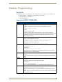
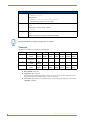
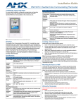
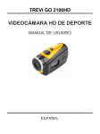
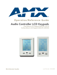
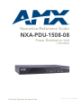
NXA-PDU-1508-08 Power Distribution Unit (110V/220V) Operation/Reference Guide Operation/Reference Guide NXA-PDU-1508-08 Power Distribution Unit (110V/220V) Control System Accessories Last Revised: 3/27/2012 AMX Limited Warranty and Disclaimer This Limited Warranty and Disclaimer extends only to products purchased directly from AMX or an AMX Authorized Partner which include AMX Dealers, Distributors, VIP’s or other AMX authorized entity. AMX warrants its products to be free of defects in material and workmanship under normal use for three (3) years from the date of purchase, with the following exceptions: • Electroluminescent and LCD Control Panels are warranted for three (3) years, except for the display and touch overlay components are warranted for a period of one (1) year. • Disk drive mechanisms, pan/tilt heads, power supplies, and MX Series products are warranted for a period of one (1) year. • AMX lighting products are guaranteed to switch on and off any load that is properly connected to our lighting products, as long as the AMX lighting products are under warranty. AMX also guarantees the control of dimmable loads that are properly connected to our lighting products. The dimming performance or quality there of is not guaranteed, impart due to the random combinations of dimmers, lamps and ballasts or transformers. • AMX software is warranted for a period of ninety (90) days. • Batteries and incandescent lamps are not covered under the warranty. • AMX AutoPatch Epica, Modula, Modula Series4, Modula CatPro Series and 8Y-3000 product models will be free of defects in materials and manufacture at the time of sale and will remain in good working order for a period of three (3) years following the date of the original sales invoice from AMX. The three-year warranty period will be extended to the life of the product (Limited Lifetime Warranty) if the warranty card is filled out by the dealer and/or end user and returned to AMX so that AMX receives it within thirty (30) days of the installation of equipment but no later than six (6) months from original AMX sales invoice date. The life of the product extends until five (5) years after AMX ceases manufacturing the product model. The Limited Lifetime Warranty applies to products in their original installation only. If a product is moved to a different installation, the Limited Lifetime Warranty will no longer apply, and the product warranty will instead be the three (3) year Limited Warranty. All products returned to AMX require a Return Material Authorization (RMA) number. The RMA number is obtained from the AMX RMA Department. The RMA number must be clearly marked on the outside of each box. The RMA is valid for a 30-day period. After the 30-day period the RMA will be cancelled. Any shipments received not consistent with the RMA, or after the RMA is cancelled, will be refused. AMX is not responsible for products returned without a valid RMA number. AMX is not liable for any damages caused by its products or for the failure of its products to perform. This includes any lost profits, lost savings, incidental damages, or consequential damages. AMX is not liable for any claim made by a third party or by an AMX Authorized Partner for a third party. This Limited Warranty does not apply to (a) any AMX product that has been modified, altered or repaired by an unauthorized agent or improperly transported, stored, installed, used, or maintained; (b) damage caused by acts of nature, including flood, erosion, or earthquake; (c) damage caused by a sustained low or high voltage situation or by a low or high voltage disturbance, including brownouts, sags, spikes, or power outages; or (d) damage caused by war, vandalism, theft, depletion, or obsolescence. This limitation of liability applies whether damages are sought, or a claim is made, under this warranty or as a tort claim (including negligence and strict product liability), a contract claim, or any other claim. This limitation of liability cannot be waived or amended by any person. This limitation of liability will be effective even if AMX or an authorized representative of AMX has been advised of the possibility of any such damages. This limitation of liability, however, will not apply to claims for personal injury. Some states do not allow a limitation of how long an implied warranty last. Some states do not allow the limitation or exclusion of incidental or consequential damages for consumer products. In such states, the limitation or exclusion of the Limited Warranty may not apply. This Limited Warranty gives the owner specific legal rights. The owner may also have other rights that vary from state to state. The owner is advised to consult applicable state laws for full determination of rights. EXCEPT AS EXPRESSLY SET FORTH IN THIS WARRANTY, AMX MAKES NO OTHER WARRANTIES, EXPRESSED OR IMPLIED, INCLUDING ANY IMPLIED WARRANTIES OF MERCHANTABILITY OR FITNESS FOR A PARTICULAR PURPOSE. AMX EXPRESSLY DISCLAIMS ALL WARRANTIES NOT STATED IN THIS LIMITED WARRANTY. ANY IMPLIED WARRANTIES THAT MAY BE IMPOSED BY LAW ARE LIMITED TO THE TERMS OF THIS LIMITED WARRANTY. EXCEPT AS OTHERWISE LIMITED BY APPLICABLE LAW, AMX RESERVES THE RIGHT TO MODIFY OR DISCONTINUE DESIGNS, SPECIFICATIONS, WARRANTIES, PRICES, AND POLICIES WITHOUT NOTICE. Table of Contents Table of Contents NXA-PDU-1508-8 (110V/220V) ...........................................................................1 Overview .................................................................................................................. 1 Product Specifications ............................................................................................. 1 SAFETY INSTRUCTIONS ........................................................................................... 4 Power Cord Requirements........................................................................................ 4 Rack-Mounting.......................................................................................................... 5 Installation ..........................................................................................................7 Front Panel Components .......................................................................................... 7 RESET Pushbutton........................................................................................................... 7 Rear Panel Components............................................................................................ 7 AXLINK POWER Connectors 1-8 ..................................................................................... 7 MASTER Connector......................................................................................................... 8 TEMP Connector ............................................................................................................. 8 Preparing Captive Wires ................................................................................................. 8 AxLink Data and Power Connections ........................................................................ 8 AxLink Wiring Guidelines ................................................................................................ 9 CONFIG DIP Switch .................................................................................................. 9 Setting the Device Address of the PDU .......................................................................... 9 Power Outlets 1-8................................................................................................... 10 Power Inlet ............................................................................................................. 10 Powering Up The NXA-PDU-1508-8 ....................................................................... 10 Initial Response Time .................................................................................................... 10 Persistence of On/Off States for All Outlets ................................................................. 10 NetLinx Programming ......................................................................................11 Device IDs............................................................................................................... 11 Supported SEND_COMMANDs .............................................................................. 11 PERSIST ..................................................................................................................................... ?PERSIST ................................................................................................................................... ?PHASEANGLE.......................................................................................................................... RESET ........................................................................................................................................ ?SERIAL ..................................................................................................................................... TRIGGER.................................................................................................................................... ?TRIGGER .................................................................................................................................. VER............................................................................................................................................ ZAP!........................................................................................................................................... 11 11 11 11 11 11 12 12 12 Channels ................................................................................................................. 12 Levels...................................................................................................................... 13 Resetting Level 4 (Accumulated Energy Reading) ......................................................... 13 Overcurrent Reporting ........................................................................................... 13 NXA-PDU-1508-8 Power Distribution Unit i Table of Contents ii NXA-PDU-1508-8 Power Distribution Unit NXA-PDU-1508-8 (110V/220V) NXA-PDU-1508-8 (110V/220V) Overview The NXA-PDU-1508-8 Power Distribution Unit (FG673-01) provides switching of mains power to each of eight AC power outlets. The two built-in AxLink bus strips provide connectivity (AxLink data / power) for up to eight AxLink connections. AxLink BANK 1 Status LED AxLink BANK 2 Status LED POWER (Output 1-8 Status) LEDs AxLink STATUS LED AXLINK POWER Connectors top = BANK 1 (1-4) bottom = BANK 2 (5-8) RESET pushbutton Power Outlets 1-8 Power Inlet 8 7 6 5 4 3 2 1 CONFIG DIP Switch TEMP (RTS) Input Connector MASTER AxLink Connector (to NetLinx Master Controller) FIG. 1 NXA-PDU-1508-8 Product Specifications NXA-PDU-1508-8 Specifications Power: Note: The PDU autosenses the voltage of the supplied power. • Powered via 110-220 VAC, 50/60Hz mains power on an IEC-320 C-14 connector • Required voltage = 110 to 220 VAC, 50/60Hz • Total Combined Current (including AxLink): 10A at 220V-240V 12A at 110V-120V • Idle current draw: 0.5W max AC Current: Overcurrent Notification: NXA-PDU-1508-8 Power Distribution Unit • 110-120VAC: Input: 15A Regulatory Derated Input Current (North America)12A @ 110 VAC 10A Max Load Per Outlet @ 110VAC 12A Max Combined Load @ 110VAC • 220-240VAC: Input: 10A @ 220 VAC 8A Max Load Per Outlet @ 220VAC 10A Max Combined Load @ 220VAC • 110-120VAC: Single Outlet: 10A Overall: 12A • 220-240VAC: Single Outlet: 8A Overall: 10A 1 NXA-PDU-1508-8 (110V/220V) NXA-PDU-1508-8 Specifications (Cont.) Front Panel Components: POWER LEDs (1-8): Eight green LEDs illuminate to indicate that the associated Power Outlet (#1 - #8) is in use. AXLINK LEDs: Two red LEDs illuminate to indicate when the associated AxLink Bus Strips (Bank 1 or Bank 2) on the PDU is in use. AXLINK STATUS LED: Green LED illuminates to indicate AxLink communication activity between the PDU and the NetLinx Master: • ON - power, no master connection • OFF - no power • Blink - powered, communicating with master RESET pushbutton: • Press/hold for 3 seconds: Resets the AxLink power line (minimum 0.5 seconds toggle) • Press/hold for 17 seconds: Resets the PDU (similar to a full power cycle of the unit) Rear Panel Components: AXLINK POWER connectors (8): A 13.5VDC, 6.5A power supply is provided for AxLink power. Eight 3.5mm (4-pin) AxLink captive-wire connectors provide power and data for up to eight AxLink connections. • AxLink power is switched in two banks of four outputs each. BANK 1 contains AxLink connectors 1-4 BANK 2 contains AxLink connectors 5-8 • The PDU provides up to 6.5A total across all AxLink outputs. MASTER connector 3.5mm Phoenix (4-pin) AxLink connector provides connectivity to the NetLinx Master (always on). TEMP (RTS) input: 3.5mm Phoenix (2 pin) connector provides connection to a Remote Temperature Sensor (RTS). CONFIG DIP Switch: Eight-position DIP switch sets the AxLink device address. Power Outlets (8): • Connector Type: IEC C-13, 12A/10A • Maximum allowable current on a single high-voltage output: 10A@110VAC / 8A@220VAC Power Inlet (1): • Connector Type: IEC C-14, 12A/10A 110-120VAC: 12A Input 220-240VAC: 10A Input Dimensions (HWD): • 1 3/16" x 17" x 9 11/16" (2.97cm x 43.18cm x 24.54 cm) • 1 RU Weight: 9 lbs (4.08 kg) Enclosure: Steel, black powder coated finish Environmental: • Operating Environment: 0°C - 40°C (32°F - 104°F) • Storage Environment: -10°C - 60°C (14°F - 140°F) • Relative Humidity: 5% - 85%, non-condensing Certifications: • CE • CB Scheme • UL Included Accessories: • Power Cord, NEMA 5-15P TO C13, 15A, 14/3, 6’ (64-0673-01) • FCC • CSA • C-Tick Note: See Power Cord Requirements below for details. • ENV-VST-TSO, Temperature Sensor (FG2050-22) • (2) Removable mounting brackets • (9) 4-pin, 3.5mm captive-wire connectors (41-5047) Other AMX Equipment: 2 • ENV-VST-TSF, Flush Mount Temperature Sensor (FG2050-21) • CC-C13-C14: C13 to C14 Power Cable (FG10-673-01) • CC-C14-NEMA: C14 to NEMA Power Cable (FG10-673-02) NXA-PDU-1508-8 Power Distribution Unit NXA-PDU-1508-8 (110V/220V) The following table lists the specifications for the ENV-VST-TSO Outdoor Temperature Sensor: ENV-VST-TSO Outdoor Temperature Sensor Specifications Sensing Element: Thermistor (thermal resistor) Accuracy: ±0.6° C from -20° to 60° C Temperature Range: -50° C to 110° C Temperature Response: NTC Thermistor Connection: 1" (2 1/2 cm) 24 AWG pigtails Mounting: Surface mount or 1/4" hole Color: White plastic case Threaded Case Length: 1 3/16 in. (30 mm) Threaded Case Diameter: 1/4 in. (7 mm) Sensor Face Diameter: 1/4 in. (7 mm) Sensor Face Thickness: 1/13 in. (2 mm) Weight: 0.88 oz. (29.94 g) NXA-PDU-1508-8 Power Distribution Unit 3 NXA-PDU-1508-8 (110V/220V) SAFETY INSTRUCTIONS There are NO user serviceable parts within the NXA-PDU-1508-8. The NXA-PDU-1508-8 is intended for indoor use only. DO NOT install or operate the NXA-PDU-1508-8 in an area where the ambient temperature exceeds 40ºC (104ºF) or falls below 0ºC (32ºF). DO NOT install or operate the NXA-PDU-1508-8 in an area in which the ambient relative humidity exceeds 85% or an area that is prone to condensation. DO NOT install or operate the NXA-PDU-1508-8 near water or in a location which may be prone to water seepage, dripping or splashing. DO NOT place objects containing liquids on the NXA-PDU-1508-8. FIG. 2 SAFETY INSTRUCTIONS FIG. 3 CLASS A NOTIFICATION Power Cord Requirements The NXA-PDU-1508-8 ships with a power cord, except to those countries which prohibit the shipment of the power cord selected. When selecting a power cord for use in Japan, please consider the following: The NXA-PDU-1508-8 requires a type VCTF or HVCTF and 1.25 or 2.0 sq.mm jacketed power cord with connectors and plugs that are 125V-12A or 125V-15A rated should be used. 4 NXA-PDU-1508-8 Power Distribution Unit NXA-PDU-1508-8 (110V/220V) Rack-Mounting For safety, the socket-outlet should be installed near the NXA-PDU-1508-8 and must be easily accessible. Before rack mounting the PDU, pay particular attention to the following factors: Temperature: Since the temperature within a rack assembly may be higher than the ambient room temperature, check that the rack-environment temperature is within the specified operating temperature range. Mechanical Loading: Do not place any equipment on top of a rack-mounted unit. Circuit Overloading: Be sure that the supply circuit to the rack assembly is not overloaded. Grounding: Rack-mounted equipment should be properly grounded. Particular attention should be given to supply connections other than direct connections to the mains. The NXA-PDU-1508-8 can be mounted in a standard 19-inch equipment rack: 1. Attach the brackets to the PDU using the bracket screws provided in the Bracket Mounting Kit (FIG. 4). Mounting bracket Bracket screws PDU FIG. 4 Attaching the Brackets 2. Mount the PDU in the rack, using 4 rack-mounting screws (not provided, see FIG. 5). Rail on equipment rack Mounting bracket on PDU FIG. 5 Installing the PDU in a Rack NXA-PDU-1508-8 Power Distribution Unit 5 NXA-PDU-1508-8 (110V/220V) 6 NXA-PDU-1508-8 Power Distribution Unit Installation Installation Front Panel Components The front panel components of the NXA-PDU-1508-8 are shown in FIG. 6: AxLink BANK 2 Status LED AxLink BANK 1 Status LED POWER (Output 1-8 Status) LEDs AxLink STATUS LED RESET pushbutton FIG. 6 NXA-PDU-1508-8 - Front Panel Components See the Specifications table for descriptions of the LEDs on the front panel. RESET Pushbutton The RESET pushbutton is a momentary breaker reset switch for the MASTER AxLink power connection. Press/hold for 3 seconds: Resets the AxLink power line (minimum 0.5 second toggle). Holding the RESET pushbutton disconnects the master AxLink power for at least 0.5 seconds. Press/hold for 17 seconds: Resets the PDU (similar to a full power cycle of the unit). Rear Panel Components The rear panel components of the NXA-PDU-1508-8 are described below (FIG. 7): AXLINK POWER Connectors top = BANK 1 (1-4) bottom = BANK 2 (5-8) Power Outlets 1-8 Power Inlet 8 7 6 5 4 3 2 1 CONFIG DIP Switch TEMP (RTS) Input Connector FIG. 7 NXA-PDU-1508-8 - Rear Panel Components AXLINK POWER Connectors 1-8 The eight AxLink connectors (labelled “AXLINK POWER”) are standard 4-pin AxLink captive-wire connectors that provide data and power for up to 8 AxLink connections. The AxLink device connectors are separated into two Banks: BANK 1 (top) includes AxLink connectors 1-4, numbered from right-to-left (see FIG. 7) BANK 2 (bottom) contains AxLink connectors 5-8, numbered from right-to-left (see FIG. 7) The PDU provides switched power to banks 1 and 2. The AxLink bus strip does not provide switching on AxLink data lines. NXA-PDU-1508-8 Power Distribution Unit 7 Installation MASTER Connector The 3.5mm 4-pin captive-wire AxLink connector labelled “MASTER” provides AxLink connectivity between the PDU and the NetLinx Master (see FIG. 7). This connector is always ON. TEMP Connector The 3.5mm 2-pin captive-wire connector labelled “TEMP” (see FIG. 7) provides the option to connect a Remote Temperature Sensor (RTS). The NXA-PDU-1508-8 comes with one ENV-VST-TSO Temperature Sensor (FG2050-22). Connect either wire from the RTS to either pin on the TEMP connector (FIG. 8). RTS ENV-VST-TSO (remote temperature sensor) NXA-PDU-1508-8 FIG. 8 TEMP Connector The NXA-PDU-1508-8 is also compatible with the ENV-VST-TSF Indoor Flush Mount Temperature Sensor (FG2050-21 - not included). Preparing Captive Wires 1. Strip 0.25 inch (6.35 mm) of wire insulation off all wires. 2. Insert each wire into the appropriate opening on the connector according to the wiring diagrams and connector types described in this section. 3. Turn the flat-head screws clockwise to secure the wires in the connector. Do not over-torque the screws; doing so can bend the seating pins and damage the connector. AxLink Data and Power Connections Connect the AxLink device’s AxLink connector to one of the AxLink connectors (1-8) on the rear panel of the PDU for data and 12 VDC power as shown in FIG. 9. PWR AXP AXM GND NXA-PDU-1508-8 (see note below) PWR AXP AXM GND AxLink Device FIG. 9 AxLink straight-thru wiring If the PDU is connected to a NetLinx Master that is self-powered (powered by a stand-alone power supply other than the PDU, or the DVX-2100HD which features an internal power supply), do not use the AxLink Power connection between the PDU and the NetLinx Master. 8 NXA-PDU-1508-8 Power Distribution Unit Installation AxLink Wiring Guidelines AxLink devices require 12 VDC power to operate properly. The necessary power is supplied via the AxLink cable. The maximum AxLink wiring distance is determined by power consumption, supplied voltage, and the wire gauge used for the cable. Use the 3-step formula below to calculate the maximum wiring lengths allowable between the PDU and connected AxLink devices. 1. <Total current consumption of all connected AxLink devices> x <Resistance/Foot> x 2 = <voltage drop per foot> (see table below for Resistance/Foot values.) 2. <Power supply voltage> - 12 VDC = <surplus voltage dissipation for cable run>. 3. <surplus voltage dissipation for cable run> / <voltage drop per foot> = Max. distance. The following table lists the resistance factors used in the formula. Cable Gauge/Resistance Factors Solid Copper Wiring Stranded Copper Wiring Wire gauge Resistance/Foot Resistance/Foot 18 AWG .00639 .00692 20 AWG .0101 .01090 22 AWG .0162 .01690 24 AWG .0257 .02770 CONFIG DIP Switch The NXA-PDU-1508-8 uses an 8-position DIP Switch (labelled “CONFIG”) to specify a unique device address for itself in a NetLinx Control System (FIG. 10). 1 2 3 4 5 6 7 8 FIG. 10 CONFIG DIP Switch Setting the Device Address of the PDU The NXA-PDU-1508-8 firmware implements 8 AxLink device IDs, starting from the device ID denoted by the DIP switch. The device IDs used by the NXA-PDU-1508-8 are as follows: Dev 1: (Power Outlet 1) + (AxLink-Bank 1 Power) + (Input Voltage) + (Temp) Dev 2: (Power Outlet 2) + (AxLink-Bank 2 Power) Dev 3-8: (Power Outlets 3-8) AxLink devices IDs are always in the range of 1-255. However, the PDU requires seven open device numbers above the PDU device number setting to accommodate its sub-devices. Therefore, device addresses 249-255 are not valid for the PDU. To set the Device Address: 1. If connected, disconnect the power supply. 2. Set the CONFIG DIP switch according to the values shown below: Switch Value 1 1 2 2 3 4 4 8 5 16 6 32 7 64 8 128 The device number is set by the total value of DIP switch positions that are in the ON position. Note that the ON position is indicated on the DIP Switch. If you later change the device number, remove and reconnect the power connector to enter the new device number into memory. Use the "Dip Switch2" software application to calculate dip switch position values (available to download from www.amx.com). NXA-PDU-1508-8 Power Distribution Unit 9 Installation Power Outlets 1-8 The eight 110-220VAC 50/60Hz, IEC C-13, 15A AC Power Outlet Connectors provide AC power to connected devices (see FIG. 7). Maximum load on a single outlet = 10A @ 110-120 VAC / 8A @ 220-240VAC. Power Inlet The IEC C-14, 15A power inlet connector provides 110-220VAC, 50/60Hz mains power to the PDU. Powering Up The NXA-PDU-1508-8 When power is applied to the PDU for the first time, the outlets are powered in sequence (1-8), with a delay of 0.5 second between outlets. By default, the state of all outlets upon initial power-up is ON. Initial Response Time Allow the PDU approximately ten seconds after it appears online to register internal processes before attempting to turn on a channel. Persistence of On/Off States for All Outlets By default, Persistence for all outlets is set to ON. Persistence can be turned off via the PERSIST Send_Command (page 11). For subsequent power-ups (from a power off state or on system reset), the PDU will restore the last recorded state of any outlet in a sequenced fashion, starting from outlet 1 in numerical order, with a delay of 0.5 second between energizing any two outlets, assuming the default Persistence setting of ON has not been changed. 10 NXA-PDU-1508-8 Power Distribution Unit NetLinx Programming NetLinx Programming Device IDs The NXA-PDU-1508-8 uses 8 AxLink device IDs, starting from the device ID denoted by the DIP switch: Dev 1: Output 1 + AxLink Power 1 + Input Voltage + Temperature Dev 2: Output 2 + AxLink Power 2 Dev 3-8: Outputs 3-8 Supported SEND_COMMANDs SEND_COMMANDs PERSIST Configures the designated power outlet to return to the last state on loss of power or reset of the PDU. By default, a shipping PDU shall have all power outlets PERSIST setting ON. Syntax: PERSIST-<outlet #>=<value> Variables: • <value> may be ON or OFF • <outlet#> 1-8 for AC outlets, 9 and 10 for AxLink 1 and 2 bus power, respectively. Note: As there are limited write cycles to the storage of the persistent data, setting an outlet to PERSIST ON should only be used when absolutely necessary, and never for very frequent toggling operations. ?PERSIST Queries the PERSIST state of all outlets. Returns a comma-delimited list in the form: PERSIST-1=<value>,2=<value>,3=<value>,4=<value>,5=<value>, 6=<value>,7=<value>,8=<value>,9=<value>,10=<value> <value> will be 1 for ON or 0 for OFF, (e.g.): PERSIST-1=1,2=0,3=0,4=0,5=0,6=0,7=0,8=0,9=1,10=0 ?PHASEANGLE Syntax: ?PHASEANGLE-<outlet #> Responds with: PHASEANGLE-<outlet #>=<Phase Angle> Note: "Phase angle" is the difference in phase between Voltage and Current, useful for determining inductive vs. capacitive loading. RESET Syntax: RESET Triggers a Power-On-Reset of the PDU. A Power-On-Reset toggles all interruptible power outlets. ?SERIAL Syntax: ?SERIAL Retrieves the 16-byte serial number assigned to the PDU. Responds with: SERIAL <XXXXXXXXXXXXXXXX> where <XXXXXXXXXXXXXXXX> is the 16-byte serial number assigned to the unit. TRIGGER Syntax: TRIGGER-<outlet #>=<Power Sense Trigger> Sets the Power Sense Trigger of the specified outlet to the specified value in tenths of Watts. Note: A "Trigger" is a current level which will cause a power sense channel to activate if the current exceeds the value. NXA-PDU-1508-8 Power Distribution Unit 11 NetLinx Programming SEND_COMMANDs (Cont.) ?TRIGGER Syntax: ?TRIGGER-<outlet #> Responds with: TRIGGER-<outlet #>=<Power Sense Trigger> to report the trigger value in use on the outlet. VER Syntax: VER Responds with: Version (string) - example: "Vx.xx" ZAP! Syntax: ZAP! Restores all settings on the PDU to factory default settings. Unsupported options in responses are ignored / not reported. Channels The PDU uses channels as specified in the following table. Channel Dev 1 1 Relay On/Off Dev 2 2 Temp Scale (off=C/on=F) 3 Ax 1 On/Off Ax 2 On/Off 255 Power Sense Power Sense Relay On/Off Dev 3 Dev 4 Dev 5 Dev 6 Dev 7 Dev 8 Relay On/Off Relay On/Off Relay On/Off Relay On/Off Relay On/Off Relay On/Off Power Sense Power Sense Power Sense Power Sense Power Sense Power Sense Relay On/Off: relay status Temp Scale: Off = C, On = F, The PDU measures temperature with an accuracy of 1 degree C) via a remote temperature probe. Temperature kept in non-volatile storage to retain across reboot. Power Sense: Signals that power (in watts) is above or below the specified trigger level (set via the TRIGGER command). 12 NXA-PDU-1508-8 Power Distribution Unit NetLinx Programming Levels 16-bit Level Dev 1 Dev 2 Dev 3 Dev 4 Dev 5 Dev 6 Dev 7 Dev 8 1 Power Power Power Power Power Power Power Power 2 Current Current Current Current Current Current Current Current 3 Power Factor Power Factor Power Factor Power Factor Power Factor Power Factor Power Factor Power Factor 4 Energy Energy Energy Energy Energy Energy Energy Energy 5 Input Voltage Ax Voltage 6 Ax 1 Power Ax 2 Power 7 Ax 1 Current Ax 2 Current 8 Temp Power (W): Resolution to 0.1W (data scale factor = 10) Current (A): Resolution to 0.1A (data scale factor = 10) Voltage (V): Resolution to 0.1V (data scale factor = 10) Power Factor: W/VA, 2 decimal places (data scale factor = 100). "Power Factor " is the ratio of real power to apparent power. For power factor, AMX has added an offset of 100 to the value to cope with the possibility of negative numbers. To obtain the correct value of the power factor, first subtract 100 from the level returned by the PDU, then divide by 100. Example: fPowerFactor1 = (LEVEL.VALUE-100)/100.0 //NB fPowerFactor1 is a FLOAT variable” The level range is 0-200. Energy (kW-hr): Power over time, resolution to 0.1kW-hr (data scale factor = 10) Temp (Degrees C or F): Resolution to 0.1C (data scale factor = 10, writing 0 resets counter) Resetting Level 4 (Accumulated Energy Reading) The Level 4 value (accumulated energy reading) can be reset to 0 (zero) in three ways: 1. When the PDU is reset or power cycled, Level 4 will go to 0 on all outputs (see Powering Up The NXAPDU-1508-8 on page 10). 2. If SEND_LEVEL <PDU dev>,4,0 is sent, Level 4 will go to 0 on that output (if not already at 0). 3. The max value of the level is 65535, if that is exceeded the level will roll over to 0. Overcurrent Reporting The PDU reports alerts of overcurrent via the following AxLink string: OVERCURRENT-<Outlet #>=<Current> If reporting overcurrent for the entire unit, the outlet # is specified as 0 (zero). NXA-PDU-1508-8 Power Distribution Unit 13 NetLinx Programming 14 NXA-PDU-1508-8 Power Distribution Unit Upgrading Firmware NXA-PDU-1508-8 Power Distribution Unit 15 In the ever-changing AV industry, continual education is key to success. AMX University is dedicated to ensuring that you have the opportunity to gather the information and experience you need to deliver strong AMX solutions. Plus, AMX courses also help you earn CEDIA, NSCA, InfoComm, and AMX continuing education units (CEUs). 3/12 ©2012 Visit AMX University online for 24/7/365 access to: - Schedules and registration for any AMX University course - Travel and hotel information - Your individual certification requirements and progress AMX. All rights reserved. AMX and the AMX logo are registered trademarks of AMX. AMX reserves the right to alter specifications without notice at any time. Increase Your Revenue through education + knowledge 3000 RESEARCH DRIVE, RICHARDSON, TX 75082 USA • 800.222.0193 • 469.624.8000 • 469-624-7153 fax • 800.932.6993 technical support • www.amx.com