1
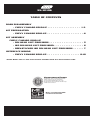
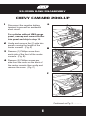
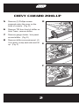
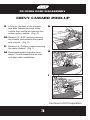
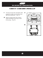
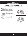
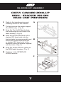
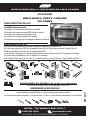
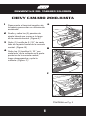
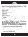
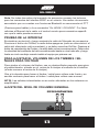
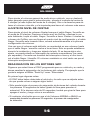
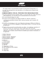
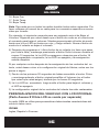
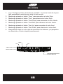
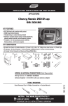
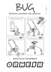
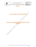
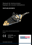
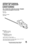
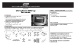
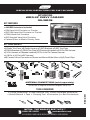
INSTALLATION INSTRUCTIONS FOR PART 99-3010S
APPLICATIONS
2010-UP CHEVY CAMARO
99-3010S
KIT FEATURES
• AXXESS Interface included
• DIN Head Unit Provision w/ Pocket
• ISO DIN Head Unit Provision w/ Pocket
• DDIN Head Unit Provision
• ISO Stacked Head Unit Provision
• Painted Silver to Match Factory Dash
KIT COMPONENTS
•A) Radio Trim Panel •B) Radio Housing •C) ISO Brackets •D) ISO Trim Plate
•E) DDIN Brackets •F) DDIN Trim Plate •G) Pocket •H) Interface •I) 20 Pin GM Harness
•J) 4 Pin Harness w/ Stripped Leads •K) 22 Pin to 44 Pin Camaro Harness
•L) 18 Pin to 10 Pin HVAC Harness
•M) Female 3.5mm Connector w/ Brown and Brown/White Wires •N) (2) Panel Clips
A
H
B
I
D
C
J
E
K
G
F
L
M
4 pin
10 pin
18 pin
ANTENNA CONNECTIONS (sold separately)
•40-EU55 European Antenna Adapter 2006-UP
6
2.5
1.5
M2.6
M3
ISO
M5
R
M3.5
M4
WIRE
CUTTE
METRA. THE WORLD’S BEST KITS.™
metraonline.com
1-800-221-0932
© COPYRIGHT 2004-2010 METRA ELECTRONICS CORPORATION
REV. 2/9/11
TOOLS REQUIRED
• Phillips Screwdriver • Panel Removal Tool • Small Flat Blade Screwdriver
• Socket Wrench • Tape • Crimping Tool •Connectors (i.e. Butt Connectors)
IGNIT
TERM ION
INALS
N
99-3010S
TABLE OF CONTENTS
DASH DISASSEMBLY
• CHEVY CAMARO 2010-UP . . . . . . . . . . . . . . . . . . 1-3
KIT PREPARATION
• CHEVY CAMARO 2010-UP . . . . . . . . . . . . . . . . . . . . 4
KIT ASSEMBLY
CHEVY CAMARO 2010-UP
• DIN HEAD UNIT PROVISION . . . . . . . . . . . . . . . . . . . 5
• ISO DIN HEAD UNIT PROVISION . . . . . . . . . . . . . . . . 6
• DDIN/STACKED ISO DIN HEAD UNIT PROVISION . . . . . . 7
IINTERFACE WIRING
• CHEVY CAMARO 2010-UP . . . . . . . . . . . . . . . . . . 8-18
*NOTE: Refer Also to the instructions included with the aftermarket radio.
KNOWLEDGE IS POWER
Enhance your installation and fabrication skills by
enrolling in the most recognized and respected
mobile electronics school in our industry.
Log onto www.installerinstitute.com or call
800-354-6782 for more information and take steps
toward a better tomorrow.
Metra recommends MECP
certified technicians
99-3010S DASH DISASSEMBLY
CHEVY CAMARO 2010-UP
1
A
Disconnect the negative battery
terminal to prevent an accidental
short circuit.
For vehicles without UMQ gauge
panel, unsnap and remove shifter
trim panel and skip to step 10.
0
30
70
100
12
9
200
19
300
30
180
320
2 Unclip and remove the (2) side trim
panels running the length of the
center console. (Fig. A)
B
3 Remove (1) Phillips screw from
each side of the front of the center
console. (Fig. B)
4 Remove (2) Phillips screws per
0
30
70
100
side from the cover on the back of
the center console then unclip and
remove the cover. (Fig. C)
12
9
200
19
300
30
180
320
C
0
30
70
100
12
9
200
19
300
30
180
320
Continued on Pg. 2 .............
1
CHEVY CAMARO 2010-UP
5
Remove (2) Phillips screws
exposed under the cover on the
back of console. (Fig. D)
D
0
30
70
100
12
9
200
19
300
30
180
320
6
Remove T20 from front of shifter on
Auto Trans., remove shifter.
7
Remove gauge cluster / trim panel
around shifter. (Fig. E)
8
Remove shifter surround panel, (4)
7mm bolts, unclip each side and lift
up. (Fig. F)
E
0
30
70
100
12
9
200
19
300
30
180
320
F
2
99-3010S DASH DISASSEMBLY
CHEVY CAMARO 2010-UP
9 Lift up on the rear of the console
and slide toward the back of the
vehicle then unclip and remove the
entire center console. (Fig. G)
G
10 Remove (2) 9/32” screws securing
the climate control/radio trim panel
and remove. (Fig. H)
11 Remove (4) Phillips screws securing
the radio chassis. (Fig. I)
H
12 Reassemble parts together from
steps 7-9 and reassemble as one
unit after radio installation.
I
Continue to Kit Preparation
3
99-3010S KIT PREPARATION
CHEVY CAMARO 2010-UP
1
Cut and remove the sub dash radio
support to make room for the interface and harnesses. (Fig. A)
A
2 Remove panel clips from factory
radio and attach to the top of the
kit housing. (Fig. B)
B
4
99-3010S KIT ASSEMBLY
CHEVY CAMARO 2010-UP
DIN HEAD UNIT PROVISION
1
A
Refer to the interface wiring and
installing section of this manaul.
2 Slide the DIN cage into the Radio
Housing and secure by bending the
metal locking tabs down. (Fig. A)
3 Snap the Pocket into the bottom
opening of the radio housing.
(Fig. B)
4 Slide the aftermarket head unit into
the cage and secure. (Fig. B)
5 Continue to the INTERFACE
WIRING section.
5
B
99-3010S KIT ASSEMBLY
CHEVY CAMARO 2010-UP
ISO DIN HEAD UNIT PROVISION
1
A
Refer to the interface wiring and
installing section of this manaul.
2 Mount the ISO Brackets to the head
unit with the screws supplied with
the unit. (Fig. A)
3 Snap the Pocket into the bottom
opening of the radio housing.
(Fig. B)
4 Slide the head unit into the radio
opening until the side clips engage.
(Fig. B)
B
5 Snap the Trim plate into the Radio
Housing. (Fig. C)
6 Continue to the INTERFACE
WIRING section.
C
6
99-3010S KIT ASSEMBLY
CHEVY CAMARO 2010-UP
DDIN / STACKED ISO DIN
HEAD UNIT PROVISION
1
A
Refer to the interface wiring and
installing section of this manaul.
2 Cut and remove the center support
(For DDIN only). (Fig. A)
3 Snap the Double DIN brackets to
the inside edge of the Double DIN
radio housing. (Fig. B)
4 Slide the Double DIN head unit or
stacked ISO head units into the
bracket/radio housing assembly and
secure the Double DIN head unit
or stacked ISO head units to the
assembly using the screws supplied
with the radio. (Fig. C)
B
5 Snap the double DIN trim plate into
the DDIN radio housing. (Fig. C)
6 Continue to the INTERFACE
WIRING section.
C
7
99-3010S
CHEVY CAMARO 2010-UP
INTERFACE WIRING
*Important: Before beginning any of the following, disconnect the
negative battery terminal to prevent an accidental short circuit.
The interface is a solution to add an aftermarket radio into GM vehicles.
Whether the vehicle is amplified or non-amplified, Onstar, Bluetooth, or
steering wheel controls, the interface can retain it. All the warning chimes are
retained that are normally lost when the OEM radio is removed. The interface
also provides a 12 volt 10 amp accessory output and navigation outputs to
help install a navigation radio which include VSS, Parking Brake,
and Reverse.
Interface Components
Interface
4 pin harness with stripped leads
20 pin GM Harness
22 pin to 44 pin Camaro Harness
18 pin to 10 pin HVAC Harness
Female 3.5mm connector with Brown and Brown/White wires
Tools Required For Installation
Cutting Tool
Tape
Crimping Tool
Connectors (I.E. butt-connectors, bell, caps, etc…)
8
99-3010S
Installing The Interface
*Important: Before beginning any of the following, disconnect the negative
battery terminal to prevent an accidental short circuit.
1. FROM THE 20 PIN HARNESS:
Connect the Red wire to the ignition/accessory wire of the aftermarket radio.
Connect the Orange/White wire to the illumination wire of the aftermarket radio. If the aftermarket radio has no illumination wire just tape off the Orange/
White wire.
Connect the Blue/White wire to the amp turn on wire of the aftermarket radio.
Connect the Brown wire to the mute wire of the aftermarket radio. If the aftermarket radio does not have a Mute wire, tape up the Brown wire.
NOTE: If the radio shuts off when OnStar is activated even though the Mute
wire is connected, you may need to add a resistor between the switched 12V
wire and the mute line. We suggest 10K ohms. If the radio still shuts off, you
may want to reduce the resistor value. If the radio mutes at inappropriate
times (such as when the lights are switched on or off), the resistor value may
need to be increased.
The Black/Yellow wire will be discussed later on in the instructions.
FOR NON-AMPLIFIED SYSTEMS
Connect the White wire to the left front positive speaker output of the aftermarket radio.
Connect the White/Black wire to the left front negative speaker output of the
aftermarket radio.
Connect the Gray wire to the right front positive speaker output of the after
market radio.
Connect the Gray/Black wire to the right front negative speaker output of the
aftermarket radio.
9
99-3010S
FOR AMPLIFIED SYSTEMS
Connect the White rca to the left front low level output of the aftermarket radio.
Connect the Gray rca to the right front low level output of the aftermarket radio.
Connect the Green rca to the left rear low level output of the aftermarket radio.
Connect the Violet rca to the right rear low level output of the aftermarket radio.
The following wires are for the aftermarket radios with navigation:
Connect the Green wire to the parking brake wire of the aftermarket navigation
radio.
Connect the Blue/Pink wire to the VSS or speed sense wire of the aftermarket
navigation radio.
Connect the Green/Purple wire to the reverse wire of the aftermarket navigation radio.
2. FROM THE 22 WAY HARNESS:
Connect the Black wire with the ring terminal to the back of the aftermarket
radio chassis.
Connect the 3.5mm jack to your aftermarket radios steering wheel control input
(if equipped).
NOTE: If using an Eclipse or Kenwood radio, use supplied female a 3.5 adaptor.
* For Kenwood radios: Connect the Kenwood SWC wire (normally Blue/Yellow)
to the Brown wire of the ASWC. Isolate and tape the Brown/White wire,
it will not be used.
* For Eclipse radios: Connect the Eclipse SWC wires (Normally Brown and
Brown/Black) to the Brown and Brown/White wires of the ASWC. Brown
connected to Brown and Brown/White connected to Brown/Black.
10
99-3010S
3. FROM THE 44 WAY HARNESS:
Connect the Black wire to the ground wire of the aftermarket radio.
Connect the RCA’s to the AUX in on the aftermarket radio (if equipped)
NOTE: This will allow you to retain the 3.5 AUX JACK in the console.
Connect the Yellow wire to the 12-volt constant wire of the aftermarket radio.
The interface comes set up for amplified systems. If the vehicle is not amplified disconnect the 4 pin harness located between the 44 way and 22 way
connector.
Connect the supplied 4 pin speaker harness and connect the following:
Connect the Violet wire to the right rear positive wire of the aftermarket radio.
Connect the Violet/Black wire to the right rear negative wire of the aftermarket radio.
Connect the Green wire to the left rear positive wire of the aftermarket radio.
Connect the Green/Black wire to the left rear negative wire of the aftermarket
radio.
Connect the Pink wire to the other Pink wire located on the 18 pin-to-10 pin
HVAC harness.
INSTALLING THE INTERFACE
1. With all the connections completed, plug the 20 and 22 pin harnesses into
the interface.
2. Reconnect the negative battery terminal.
3. Plug the 44 pin GM harness into the vehicle side harness, and plug the
aftermarket radio harness into the aftermarket radio.
PROGRAMMING: You must cycle the a/c fan speed all the way to high and
back to low when you first install the kit.
11
99-3010S
NOTE: Continue to the TESTING THE INTERFACE section if you do not have
factory audio controls on the steering wheel.
PROGRAMMING THE STEERING WHEEL CONTROLS
1.
2.
3.
4.
5.
Turn on the ignition.
The SWC status LED on the interface will begin to blink rapidly.
Tap volume up steering wheel control until the LED stops blinking rapidly.
The LED will go off when it detects the car.
It will then will blink the LED the number corresponding to the radio type.
(See Radio Types below). Then the LED will remain off.
TO MANUALLY SET THE RADIO TYPE:
This action must begin 20 seconds AFTER the Key is set to ACC ON position
OR a steering wheel button is pressed that is NOT Volume Up nor
Volume Down.
1) Hold Down VOLUME DOWN button for 30 seconds
2) LED will begin to FAST blink
3) Press the VOLUME UP button the number associated with the desired radio type (as seen in the radio list below). The LED will remain ON while holding down the button & will go back to blinking when released. For example: If
the radio is a JVC, press the VOLUME UP button 5 times.
1
RADIO_ECLIPSE
RADIO_KENWOOD
2
RADIO_CLARION
3
RADIO_SONY_DUAL
4
RADIO_JVC
5
RADIO_JENSEN_PIONEER 6
RADIO_ALPINE
7
RADIO_VISTEON
8
RADIO_VALOR
9
RADIO_CLARION_5K
10
4) Press the VOLUME DOWN button to finish. The LED will then go off.
5) After a few seconds, the LED will then blink the number of times
corresponding to the radio ID type. This number should be the same
number the user has just pressed the VOLUME UP button.
12
99-3010S
TO FORCE THE UNIT TO RETRY TO
AUTO-DETECT THE RADIO:
This action must begin 20 seconds AFTER the key is set to ACC ON position OR
a steering wheel button is pressed that is NOT Volume Up nor Volume Down.
1) Hold Down VOLUME UP button for 30 seconds.
2) LED will go ON to indicate auto-detecting. (button can be released now)
3) After about 6 seconds, LED will go OFF indicating completion.
4) The LED will then blink the number of times corresponding to the radio ID type it has detected. (See Radio chart above)
Note: Not every aftermarket radio will have all of the possible swc commands
on the steering wheel. Aftermarket radios that do not have Bluetooth features
will not recognize the PTT (Push to Talk) or On Hook / Off Hook commands.
Please refer to the radios owners’ manual or wireless remote for specific
commands the radio will recognize.
TESTING THE INTERFACE
With the vehicle battery re-connected, cycle the key on and off once and back
on. Turn the ignition on, and then turn the aftermarket radio on. Push the
Onstar button, the radio should turn off (radio will mute if mute wire is connected) and you should hear Onstar. Push the Onstar cancel button and the
radio should come back on. Cycle the a/c fan speed all the way to high and
back to low when you first install the kit.
CHIME/TURN SIGNAL VOLUME ADJUSTMENT
To adjust the chime volume, use a small screwdriver to rotate the potentiometer, located on the 8 pin harness side of the interface (closest to 8 pin
harness).
Turn clockwise to make the chime/turn signal louder and counterclockwise to
make the chime/turn signal softer.
NOTE: Turn signal will not be affected in non amplified systems.
OVERALL GAIN LEVEL ADJUSTMENT
To adjust the overall audio volume of your vehicle, use a small screwdriver to
rotate the potentiometer, located on the 8 pin harness side (furthest away
13
99-3010S
POTENTIOMETERS
from 8 pin harness). Turn clockwise to make gain louder and counterclockwise to make the gain softer. (See figure on pg. 13)
ONSTAR LEVEL ADJUSTMENT
To adjust the Onstar volume level find the Black/Yellow wire on the 20 pin
harness. Push the blue Onstar button, while the voice is speaking tap the
Black/Yellow wire to ground. There are 4 volume settings for Onstar; once
the 4th setting is reached and the Black/Yellow wire is tapped to ground it will
automatically go back to the first volume setting. Once the volume is set it will
stay at that volume until the Black/Yellow wire is tapped to ground again.
This can be set during installation and then left alone.
If user adjustment is desired, a momentary contact switch (sold separately)
can be added. Connect one terminal from the switch to ground and the other
terminal to the Black/Yellow wire. The volume will change one level every
time the switch is pressed.
REMAPPING THE SWC BUTTONS
Let’s say you have the SWC programmed to your vehicle and your radio and
you want to change the button assignment for the steering wheel controls.
For instance you would like Seek Up to be Mute.
First a few notes:
• The SWC must have detected the vehicle and radio it is attached to before
you can remap any buttons.
• You can only start the remapping of the steering wheel controls process
within the first 20 seconds of turning the ignition key on. If you wait longer
14
99-3010S
then the 20 seconds you will have to turn the ignition off then back on again.
• Within the first 20 seconds if any button other then Volume Up or Volume
Down is pushed, the remapping process will stop.
• If during the remapping process no button is pushed for 30 seconds the
remapping process is aborted and the original settings are reset.
SO LET’S BEGIN THE REMAPPING PROCESS:
1) Ideally having the interface visible is recommended since you can see the
led flashes to confirm button recognition.
2) Turning off the radio is recommended
3) Within the first 20 seconds of turning the ignition on, press and hold down
the Volume Up button for at least 25 seconds.
4) The led will light up solid red. Release Volume Up and the led will go out.
Volume Up has now been programmed.
5) Follow the list below in order however pushing the steering wheel control
button you want for the function below. If you want to skip a command
press the Volume Up on the steering wheel, this will tell the interface to
skip the command and go to the next one.
1. Volume Up
2. Volume Down
3. Seek Up/Next
4. Seek Down/Prev
5. Source/Mode
6. Mute
7. Preset Up
8. Preset Down
9. Power
10. Band
11. Play/Enter
12. PTT (Push To Talk)
13. On Hook
14. Off Hook
15. Fan Up
16. Fan Down
15
99-3010S
17. Temp Up
18. Temp Down
Note: Remember not all radios will have all these commands. Please refer to
the radios’ owners manual for specific commands recognized by the radio.
For instance the next command to be mapped is the Volume Down command. Let’s say you want the Mode button on your steering wheel to be the
Volume Down command. Hold down the Mode button till the led lights up
solid red, and then release it. Now your Mode button on the steering wheel is
Volume Down.
6) After the last button is programmed on your steering wheel (you do not
have to go through the whole list), hold down the Volume Up button for
at least 10 seconds then the led will go out or after the 18th button is
programmed or skipped the led will go out and the remapping is completed.
If for any reason after remapping the steering wheel controls you want to
return to the original steering wheel control settings, follow these steps:
1) Within the first 20 seconds of turning the ignition on. Press and hold down
the original Volume Down button (not the Volume Down button you just
remapped) for at least 25 seconds.
2) The led will turn on then release the Volume Down button and the led will
turn off.
3) The original steering wheel control settings will be restored.
VEHICLE CUSTOMIZATION WITH OPTIONAL LCD
(AXXESS part # XIA-LCD sold separately)
The OEM radio is used to customize certain features of the vehicle such as:
SET_LANGUAGE
English, French, or Spanish
LOCATOR_LIGHTS
On or Off
EXIT_LIGHTING
Off, 30 seconds, or 1 minute
16
99-3010S
UNLOCKED_DOOR_AUTO_LOCKOUT
On or Off
AUTO_DOOR_UNLOCK
Off, Driver Only, or All Doors
DELAYED_LOCK
On or Off
REMOTE_UNLOCK_LIGHT_FEEDBACK
On or Off
REMOTE_LOCK_FEEDBACK
Off, Lights, Horn, or Lights & Horn
REMOTE_DOOR_UNLOCK
Driver Only or All Doors
Use the optional lcd to adjust these features accordingly:
1. Press the ESC button and PRESS ENTER TO SET LANGUAGE will
appear on the screen.
2. To change the LANGUAGE press the ENTER button then press then
press the UP and DOWN buttons to change the LANGUAGE.
3. Once you have chosen you LANGUAGE then press ESC to go back to be
able to scroll through the other settings.
4. If you do not wish to change the LANGUAGE you can scroll up and down
through the different settings with the UP and DOWN buttons.
5. Remember to press ENTER to change the desired setting.
CHANGING THE DISPLAY BACK LIGHT COLOR
1. Press the Front Defrost button for 5 seconds, the unit will go into “Configure Backlight Color” mode. The display backlight will blink while in this
mode.
2. Press and hold the Face button to increase Red.
3. Press and hold the Foot button to decrease Red.
4. Press and hold the Foot/Face button to increase Green.
5. Press and hold the Foot/Def button to decrease Green.
17
99-3010S
1. Press and hold the Fan Up button to increase Blue.
2. Press and hold the Fan Down button to decrease Blue.
3. After you choose your color stop pressing the buttons and the blinking
will stop and the color chosen will stay.
18
NOTES
NOTES
INSTRUCCIONES PARA LA INSTALACIÓN DE PARTE 99-3010S
APLICACIONES
2010-HASTA CHEVY CAMARO
99-3010S
CARACTERÍSTICAS DEL KIT
• AXXESS Interfaz incluido
• Provisión de unidad principal DIN con bolsillo
• Provisión de unidad principal ISO DIN con bolsillo
• Provisión de unidad principal Doble DIN
• Provisión de unidad principal ISO apilada
• Pintado en color gris para emparejar el tablero de fabrica
COMPONENTES DEL KIT
•A) Contorno del panel de radio •B) Caja para la radio •C) Soportes ISO
•D) Placa de guarnición ISO •E) Soportes Doble DIN •F) Placa de guarnición Doble DIN •G)
Bolsillo •H) Interfaz •I) Arnés de 20 clavijas para GM
•J) Arnés de 4 clavijas con conductores forrados •K) Arnés Camaro de 22 clavijas a 44 clavijas
•L) Arnés para climatización de 18 clavijas a 10 clavijas
•M) Conector femenino de 3.5 Mm. con cables marrón y marrón/blanco •N) (2) Panel de Clips
A
B
H
I
D
C
J
E
G
F
L
K
M
4 pin
10 pin
18 pin
N
CONEXIONES DE ANTENA (Se vende por separado)
•40-EU55 Europeo Antena Adaptador 2006-UP
M5
R
M3.5
M4
WIRE
CUTTE
IGNIT
TERM ION
INALS
ISO
M3
M2.6
1.5
6
2.5
• Destornillador estrella (Phillips) • Herramienta para quitar el panel
• Destornillador plano pequeño • Llave de tubo • Cinta • Herramienta prensadora •Conectores
METRA. THE WORLD’S BEST KITS.™
metraonline.com
1-800-221-0932
© COPYRIGHT 2004-2010 METRA ELECTRONICS CORPORATION
REV. 2/9/11
HERRAMIENTAS NECESARIAS
99-3010S
TABLA DE CONTENIDOS
DESMONTAJE DEL TABLERO
• CHEVY CAMARO 2010-HASTA . . . . . . . . . . . . . . . 1-2
PREPARACION DEL EQUIPO
• CHEVY CAMARO 2010-HASTA . . . . . . . . . . . . . . . . . 3
MONTAJE DEL EQUIPO
CHEVY CAMARO 2010-HASTA
• PROVISION DE UNIDAD PRINCIPAL DIN . . . . . . . . . . . 4
• PROVISION DE UNIDAD PRINCIPAL ISO DIN . . . . . . . . 5
• PROVISION DE UNIDAD PRINCIPAL ISO DIN/DOBLE DIN . 6
CABLEADO DEL INTERFAZ
• CHEVY CAMARO 2010-HASTA . . . . . . . . . . . . . . . .7-18
*NOTA: Consulte también las instrucciones incluidas con la radio del mercado de
accesoriosdio.
KNOWLEDGE IS POWER
Enhance your installation and fabrication skills by
enrolling in the most recognized and respected
mobile electronics school in our industry.
Log onto www.installerinstitute.com or call
800-354-6782 for more information and take steps
toward a better tomorrow.
Metra recommends MECP
certified technicians
DESMONTAJE DEL TABLERO 99-3010S
CHEVY CAMARO 2010-HASTA
1
Desconecte el terminal negativo de
la batería para evitar un cortocircuito
accidental.
A
2 Suelte y retire los (2) paneles de
ajuste lateral que corren a lo largo
de la consola central. (Figura A)
0
30
70
100
12
9
200
19
300
30
180
320
3 Quite (1) tornillo de 9 / 32 “ de cada
lado de la parte frontal de la consola
central. (Figura. B)
4 Quite los (2) tornillos 9 / 32 “ por
B
cada lado, de la cubierta en la parte
posterior de la consola central,
luego desenganche y quite la
cubierta. (Figura. C)
0
30
70
100
12
9
200
19
300
30
180
320
C
0
30
70
100
12
9
200
19
300
30
180
320
Continúe en Pg. 2
1
DESMONTAJE DEL TABLERO
CHEVY CAMARO 2010-HASTA
5
Quite los (2) tornillos de 9 / 32”
expuestos bajo la cubierta en
la parte posterior de la consola.
(Figura D)
6
Levante la parte trasera de la
consola y deslice hacia la parte
posterior del vehículo luego
desenganche y quite todo el centro
de la consola (Figura E)
7
Quite los (2) tornillos de 9 / 32” que
aseguran los controles climáticos
y el tablero de radio. Remuévalo.
(Figura F)
D
0
30
70
100
12
9
200
19
300
30
180
320
E
0
30
70
100
12
9
200
19
300
8
30
180
320
Quite los (4) tornillos que aseguran
el chasis de la radio. (Figura G)
F
G
Continúe con la preparación del equipo
2
PREPARACION DEL EQUIPO 99-3010S
CHEVY CAMARO 2010-HASTA
1
A
Corte y quite el tablero de apoyo
de la radio para hacer espacio
para la interfaz y los arneses.
(Figura A)
2 Quite los ganchos del panel de
la radio de fábrica y adjunte a
la parte superior de la caja del
equipo. (Figura B)
B
3
MONTAJE DEL EQUIPO 99-3010S
CHEVY CAMARO 2010-HASTA
PROVISION DE UNIDAD PRINCIPAL DIN
1
Consulte el cableado de la interfaz
y la sección de instalación de este
manual.
A
2 Deslice el armazón de DIN en la
caja para radio, asegúrela doblando
las lengüetas de metal hacia abajo.
(Figura A)
3 Encaje el bolsillo en la abertura
inferior de la caja de radio. (Figura B)
4 Deslice la unidad principal del
mercado de accesorios en la caja y
asegúrela. (Figura. B)
5 Vuelva a montar tablero en orden
inverso al del desmontaje usando el
panel de ajuste de radio 99-3010S
en lugar del panel de fábrica.
4
B
MONTAJE DEL EQUIPO 99-3010S
CHEVY CAMARO 2010-HASTA
PROVISION DE UNIDAD PRINCIPAL ISO DIN
1
Consulte la sección de instalación
y cableado del interfaz de este
manual.
A
2 Monte los soportes ISO a la unidad
principal con los tornillos suministrados
con la unidad. (Figura A)
3 Encaje el bolsillo en la abertura
inferior de la caja de radio (Figura B)
4 Deslice la unidad principal en la
apertura de radio hasta los broches
enganchen. (Figura B)
B
5 Ajustar la placa de guarnición en la
caja para Radio. (Figura C)
6 Vuelva a montar tablero en orden
inverso al del desmontaje usando el
panel de ajuste de radio 99-3010S
en lugar del panel de fábrica.
5
C
MONTAJE DEL EQUIPO 99-3010S
CHEVY CAMARO 2010-HASTA
PROVISION DE UNIDAD PRINCIPAL
DOBLE DIN/ DIN ISO APILADO
1
Consulte la sección de instalación y
cableado del interfaz de este manual.
A
2 Corte y quite el soporte central
(Solamente para DIN Doble).
(Figura A)
3 Ajustar los soportes Doble DIN en
el borde interior de la caja de radio
Doble DIN. (Figura B)
4 Deslice la unidad principal Doble
DIN o las unidades apiladas ISO
dentro de los soportes/caja de radio
y asegure la unidad principal Doble
DIN o las unidades apiladas ISO
utilizando los tornillos suministrados
con la radio. (Figura C)
B
5 Ajuste la placa de guarnición Doble
DIN en la caja de radio Doble DIN.
(Figura C)
6 Vuelva a montar tablero en orden
inverso al del desmontaje usando el
panel de ajuste de radio 99-3010S
en lugar de la placa de fábrica.
6
C
MONTAJE DEL EQUIPO 99-3010S
CHEVY CAMARO 2010-HASTA
CABLEADO DEL INTERFAZ
*Importante: Antes de comenzar cualquiera de los siguientes,
desconecte el terminal negativo de la batería para evitar un cortocircuito accidental.
La interfaz es la solución cuando se desea agregar una radio del mercado
de accesorios en los vehículos GM. Ya sea el vehiculo amplificado, no amplificado, tenga OnStar, Bluetooth o controles en el volante, la interfaz los conservara. Todas las campanas de alerta que normalmente se pierden cuando
la radio original de fábrica es retirada, se conservaran. La interfaz también
proporciona salida para accesorios de 10 amperios y 12 voltios, al igual que
salidas de navegación, para ayudar a instalar una radio de navegación que
incluya VVS, freno de mano y retroceso.
Componentes del interfaz
Interfaz
Arnés de 4 clavijas con terminales pelados
Arnés GM de 20 clavijas
Arnés Camaro de 22 clavijas a 44 clavijas
Arnés HVAC de 18 clavijas a 10 clavijas
Conector femenino de 3,5 mm con cables Marrón y Marrón/Blanco
Herramientas necesarias para la instalación
Herramienta para cortar
Cinta
Herramienta prensadora
Conectores (Ejemplo: conectores a tope, campana, gorras, etc...)
7
99-3010S
Instalación del Interfaz
*Importante: Antes de comenzar cualquiera de los siguientes, desconecte el
terminal negativo de la batería para evitar un cortocircuito accidental.
1. DESDE EL ARNÉS DE 20 CLAVIJAS:
Conecte el cable Rojo con el cable de encendido/accesorios de la radio del
mercado secundario.
Conecte el cable Naranja / Blanco al cable de iluminación de la radio del
mercado de accesorios. Si la radio no tiene cable de iluminación, selle con
cinta adhesiva el cable Naranja / Blanco.
Conecte el cable Azul / Blanco con el cable de encendido del amplificador de
la radio de Mercado de accesorios.
Conecte el cable Marrón al cable del silenciador de la radio del mercado de
accesorios. Si la radio del mercado de accesorios no tiene un Cable de silenciador, selle con cinta adhesiva el cable Marrón.
NOTA: Si la radio se apaga cuando se activa OnStar a pesar de que el cable
para el silenciador está conectado, puede que tenga que añadir un resistor
entre la conmutación del cable de 12V y la línea del silenciador. Sugerimos
ohmios de10K. Si la radio todavía se apaga, es posible que sea necesario
reducir el valor del resistor. Si el radio se silencia en momentos inadecuados
(por ejemplo, cuando las luces son encendidas o apagadas) puede que sea
necesario aumentar el valor del resistormay need to be increased.
El cable Negro / Amarillo se discutirá más adelante en las instrucciones.
PARA SISTEMAS NO AMPLIFICADOS
Conecte el cable Blanco a la salida positiva del altavoz frontal izquierdo de la
radio del mercado de accesorios.
Conecte el cable Blanco / Negro a la salida negativa del altavoz frontal izquierdo de la radio del mercado de accesorios.
Conecte el cable Gris a la salida positiva del altavoz frontal derecho de la
radio del mercado de accesorios
Conecte el cable Gris / Negro a la salida negativa del altavoz frontal derecho
de la radio del mercado de accesorios.
8
99-3010S
PARA SISTEMAS AMPLIFICADOS
Conecte el cable RCA Blanco en el costado delantero izquierdo de la salida
de bajo nivel de la radio del mercado de accesorios.
Conecte el cable RCA Gris en el costado delantero derecho de la salida bajo
nivel de la radio del mercado de accesorios.
Conecte el cable RCA Verde en el costado trasero izquierdo de la salida de
bajo nivel de la radio del mercado de accesorios.
Conecte el cable RCA Violeta en el costado trasero derecho de la salida de
bajo nivel de la radio del mercado de accesorios.
Los siguientes cables son para las radios del mercado de accesorios
con navegación:
Conecte el cable Verde al cable del freno de estacionamiento de la radio de
mercado de accesorios con navegación.
Conecte el cable Azul / Rosa al cable del VSS o cable de sentido la velocidad de la radio de mercado de accesorios con navegación.
Conecte el cable Verde / Violeta cable al cable de retrocesos de la radio de
mercado de accesorios con navegación.
2. DESDE EL ARNÉS DE 22 CLAVIJAS:
Conecte el cable Negro con el terminal de anillo en la parte trasera del chasis de la radio del mercado de accesorios.
Conecte el enchufe de 3,5 mm a la entrada del control del volante de su
radio de Mercado secundario (si corresponde).
NOTA: Si utiliza una radio Eclipse o Kenwood, use el adaptador femenino de
3.5 (Incluido).
Marrón/Blanco del interfaz ASWC. El Cable Marrón conectado al cable Marrón y el cable Marrón/Blanco conectado al cable Marrón/Negro.
* Para Radios Kenwood: Conecte el cable de control del volante (SWC) de
Kenwood (normalmente Azul / Amarillo) al cable marrón del interfaz ASWC.
Aislar y pegar con cinta el cable marrón / blanco, este no se utilizará.
9
99-3010S
* Para Radios Eclipse: Conecte el cable de control del Volante (SWC) de
Eclipse (Normalmente Marrón y Marrón / Negro) al cable Marrón y al cable
Marrón/Blanco del interfaz ASWC. El Cable Marrón conectado al cable Marrón y el cable Marrón/Blanco conectado al cable Marrón/Negro.
3. DESDE EL ARNES DE 44 CLAVIJAS:
Conecte el cable Negro al cable de tierra de la radio del mercado de accesorios.
Conecte el cable RCA a la entrada AUXILIAR en la radio del mercado de accesorios (si corresponde).
NOTA: Esto le permitirá mantener el enchufe auxiliar de 3.5 de la consola.
Conecte el cable amarillo a cable constante de 12 voltios de la radio del mercado de accesorios. La interfaz viene programada para los sistemas amplificados. Si su vehículo no tiene un sistema amplificado desconecte el arnés
de 4 clavijas ubicado entre el conector de 44 clavijas y el de 22.
Conecte el arnés de 4 clavijas del altavoz y conectar los siguientes:
Conecte el cable Violeta al cable trasero derecho positivo de la radio del
mercado de accesorios.
Conecte el cable Violeta / Negro al cable trasero derecho negativo de la
radio del mercado de accesorios.
Conecte el cable Verde al cable trasero izquierdo positivo de la radio del
mercado de accesorios.
Conecte el cable Verde / Negro al cable trasero izquierdo negativo de la
radio del mercado de accesorios.
Conecte el cable Rosado con el otro cable Rosado situado en el arnés HVAC
de 18 a 10 clavijas.
10
99-3010S
INSTALACIÓN DEL INTERFAZ
1. Con todas las conexiones completas, enchufe el arnés de 20 clavijas y el
de 22 al interfaz.
2. Vuelva a conectar el terminal negativo de la batería.
3. Conecte el arnés GM de 44 clavijas con arnés del lado del vehículo, y
conecte el arnés de radio del mercado de accesorios en la radio del
mercado de accesorios.
PROGRAMACIÓN: Debe subir la velocidad del ventilador del aire acondicionado hasta su nivel más alto y luego hasta su nivel mas bajo cuando instale
el equipo por primera vez.
PROGRAMACIÓN DE LOS CONTROLES DEL VOLANTE
1. Encienda el motor.
2. El estado de SWC LED en la interfaz comenzará a parpadear rápidamente.
3. Toque de aumento de volumen del control del volante hasta que el LED
deje de parpadear rápidamente.
4. El LED se apagará cuando se detecta el automóvil.
5. A continuación, el LED parpadeara el número de veces correspondientes
al tipo de radio. (Ver Tipos de Radio abajo). A continuación, el LED
permanecerá apagado.
PARA CONFIGURAR MANUALMENTE EL TIPO DE RADIO:
Esta acción debe comenzar 20 segundos DESPUES de que la llave este en
la posición ACC ON (O) cuando algún botón de los controles de volante este
presionado con EXCEPCION del de subir o bajar el volumen.
1) Mantenga presionado el botón para BAJAR EL VOLUMEN por 30 segundos.
2) LED comenzará a parpadear RAPIDAMENTE.
11
99-3010S
3) Pulse el botón para SUBIR EL VOLUMEN hasta encontrar el número
asociado con su tipo de radio (como se ve en la lista de radios). La luz LED
permanecerá encendida mientras mantenga presionado el botón y volverá
a parpadear cuando este sea soltado. Por ejemplo: Si la radio es una JVC,
pulse el botón para SUBIR EL VOLUMEN 5 veces.
RADIO_ECLIPSE
1
RADIO_KENWOOD
2
RADIO_CLARION
3
RADIO_SONY_DUAL
4
RADIO_JVC
5
RADIO_JENSEN_PIONEER 6
RADIO_ALPINE
7
RADIO_VISTEON
8
RADIO_VALOR
9
RADIO_CLARION_5K
10
4) Para terminar, presione el botón para Bajar el volumen. La luz LED se
apagará.
5) Después de unos segundos, La luz LED parpadeara el número de veces
correspondiente a la identificación del tipo de radio. Este número debe
ser el mismo número que el usuario escogió cuando presiono el botón
para SUBIR EL VOLUMEN.
PARA FORZAR A LA UNIDAD A VOLVER A INTERTAR A DETECTAR AUTOMATICAMENTE LA RADIO:
Esta acción debe comenzar 20 segundos DESPUES de que la llave este en
la posición ACC ON o cuando algún botón de los controles de volante este
presionado con EXCEPCION del de subir o bajar el volumen.
1) Presione el botón VOLUMEN ARRIBA durante 30 segundos.
2) La Luz LED se encenderá para indicar auto-detección. (Botón puede ser
liberado ahora)
3) Después de unos 6 segundos, el LED se apagará indicando elcumplimiento.
4) A continuación, el LED parpadeara el número de veces correspondientes
al tipo de radio. (Ver Tipos de Radio)
12
99-3010S
Nota: No todas las radios del mercado de accesorios poseen los botones
para los comandos del interfaz ASWC en el volante. Las radios de mercado
secundario que no cuentan con funciones Bluetooth no reconocerán el PTT
(Presione para hablar) o Los comandos “On HOOK / Off HOOK”. Por favor
referirse al Manual de la radio o al control remoto para comandos específicos que la radio pueda reconocer.
PRUEBA DE LA INTERFAZ
Encienda su automóvil y luego encienda la radio de Mercado de accesorios.
Presione el botón de OnStar, la radio debe apagarse (radio se silenciará si el
cable del silenciador está conectado) y se debe escuchar OnStar. Presione el
botón de cancelación de Onstar y la radio debe volver sucesivamente. Debe subir
la velocidad del ventilador del aire acondicionado hasta su nivel más alto y luego
hasta su nivel mas bajo cuando instale el equipo por primera vez.
PARA AJUSTAR EL VOLUMEN DE LOS TIMBRES / SEÑALES PARA VOLTEAR
Para ajustar el volumen del timbre, use un destornillador pequeño para girar
el potenciómetro, situado en el arnés de 8 clavijas al costado de la interfaz
(el más cercano al arnés de 8 clavijas).
Gire a la derecha para hacer el timbre / señal para voltear más fuerte y en
sentido contrario para hacer el timbre / señal para voltear mas suaves.
NOTA: Las señales intermitentes no se verán afectadas en los sistemas no
amplificados.
AJUSTE DEL NIVEL DE VOLUMEN GENERAL
POTENCIÓMETRO
13
99-3010S
Para ajustar el volumen general de audio de su vehículo, use un destornillador pequeño para girar el potenciómetro, situado al costado del arnés de
8 clavijas (el más lejano del arnés de 8 clavijas). Gire a la derecha para obtener el volumen más alto y a la izquierda para hacer el volumen más suave
AJUSTE DE NIVEL DE ONSTAR
Para ajustar el nivel de volumen Onstar busque el cable Negro / Amarillo en
el arnés de 20 clavijas. Presione el botón azul de OnStar, mientras la voz
este hablando, toque el cable Negro / Amarillo a tierra. Existen 4 niveles de
volumen de OnStar, una vez llegue al cuarto nivel de configuración y el cable
Negro / Amarillo este tocando tierra, volverá automáticamente a la primera
configuración de volumen.
Una vez que el volumen está definido, se mantendrá en ese volumen hasta
que el cable Negro / amarillo vuelva a tocar tierra. Esto se puede establecer
durante la instalación y luego ser dejado de lado. Si se desea algún otro
ajuste, se puede añadir un interruptor de contacto momentáneo (se vende
por separado). Conecte una terminal del interruptor a tierra y el otro terminal al cable Negro / Amarillo. El volumen cambiará un nivel cada vez que el
interruptor sea presionado.
REASIGNACION DE LOS BOTONES SWC
Digamos que usted tiene el SWC programado para su vehículo y su radio y
desea cambiar la asignación de los botones del volante. Por ejemplo que le
gustaría asignar al Botón “Seek Up” como “Silenciador”.
En primer lugar algunas notas:
• El SWC debe haber detectado el vehículo y la radio que se adjunta antes
de que pueda volver a asignar algún botón.
• Sólo puede iniciar el proceso de asignación de botones del volante durante
los primeros 20 segundos de haber girado la llave para prender el
automóvil. Si le demora más de 20 segundos, tendrá que girar la llave para
apagar el motor y luego volver a encenderlo.
• Si cualquier otro botón que no sea el de Volumen ARRIBA o ABAJO es
presionado durante los primeros 20 segundos, el proceso de reasignación
se detendrá.
14
99-3010S
• Si ningún botón es presionado durante los primeros 30 segundos, el
proceso de reasignación será abortado y la configuración original será
restablecida.
COMENCEMOS CON EL PROCESO DE REASIGNACION:
1) Se recomienda tener la interfaz visible, ya que puedes ver todas las luces
LED parpadear y así confirmar el reconocimiento de los botones.
2) Se recomienda apagar la radio
3) Durante los 20 segundos de haber prendido su vehiculo, presione y
mantenga presionado el botón Subir volumen durante, por lo menos, 25
segundos.
4) El LED se iluminará en color rojo. Deje de presionar el Botón de Subir el
volumen y la luz LED se apagara. El botón para Subir el volumen ha sido
programado.
5) Siga la lista que esta a continuación en orden, sin embargo, presione el
botón de control de volante que usted desee para las funciones
siguientes. Si desea omitir algún comando, presione el botón para subir el
volumen en el volante, esto le dirá a la interfaz que omita el comando e ir
al siguiente.
1. Subir Volumen
2. Bajar volumen
3. Buscar Arriba / Siguiente
4. Buscar Abajo / Anterior
5. Procedencia / Modo
6. Silencio
7. Preset Arriba
8. Preset Abajo
9. Encender
10. Banda
11. Reproducir / Enter
12. PTT (Presione para hablar)
13. On Hook
14. Off Hook
15. Subir Fan
15
99-3010S
16. Bajar Fan
17. Subir Temp
18. Bajar Temp
Nota: Recuerde que no todas las radios tendrán todos estos comandos. Por
favor refiérase al manual de su radio para los comandos específicos reconocidos por la radio.
Por ejemplo, el siguiente comando para ser asignado será el de Bajar el
Volumen. Digamos que usted desea que el botón de modo en el volante sea
el comando para bajar el volumen. Mantenga presionado el botón de modo
hasta que la Luz LED se ilumine en rojo, y luego soltarlo. Ahora el botón de
modo en el volante es bajar el volumen.
6) Después de programar el último botón de su volante (no tiene que pasar
por toda la lista), mantenga presionado el botón Subir volumen durante al
menos 10 segundos, la luz LED se apagara o después que el botón 18
está programado o suprimido, la luz LED se apagará y la reasignación
estará completa.
Si por cualquier motivo después de la reasignación de los controles del volante, usted desea volver a la configuración original de fábrica, estos son los
pasos a seguir:
1) Dentro de los primeros 20 segundos de haber encendido el motor. Pulse
y mantenga pulsado el botón original para Bjar el Volumen (no el botón
que usted que usted asigno) durante por lo menos 25 segundos.
2) La Luz LED se encenderá, luego suelte el botón para bajar el volumen y
el LED se apagará.
3) La configuración original de los controles del volante han sido restauradas.
PERSONALIZACION DEL VEHICULO CON LCD OPCIONAL
(Parte Axxess # XI bis-LCD se vende por separado)
La radio OEM se utiliza para personalizar determinadas características del
vehículo tales como:
IDIOMA
Ingles, Español o Frances
16
99-3010S
UBICACION DE LUCES
Prendido o Apagado
LUCES DE SALIDA
Apagado, 30 segundos o 1 minuto
PUERTA ABIERTA / CERRADO AUTOMATICO
Encendido o Apagado
ABRIR PUERTA DEL AUTOMOVIL
Apagado, Solo piloto o todas las Puertas
CERRAR
Prendido o Apagado
ABRIR CON CONTROL REMOTO
Prendido o Apagado
CERRAR CON CONTROL REMOTO
Apagado, Luces, Bocina, o Luces y Bocina
ABRIR LA PUERTA CON CONTROL REMOTO
Solo piloto o todas las puertas
Utilice la pantalla LCD opcional para ajustar estas características:
1. Pulse la tecla ESC y pulse ENTER para configurar el idioma, aparecerá
en la pantalla.
2. Para cambiar el idioma Presione el botón ENTER y luego presione los
botones ARRIBA y ABAJO para cambiar el Idioma.
3. Una vez que haya elegido su idioma, presione ESC para volver a la
configuración y poder elegir otros comandos.
4. Si usted no desea cambiar el idioma que usted puede desplazarse hacia
arriba y hacia abajo a través de las distintas configuraciones con los
botones ARRIBA y ABAJO.
5. Recuerde pulsar ENTER para cambiar la configuración deseada.
PARA CAMBIAR EL COLOR DE LA LUZ DE FONDO DE PANTALLA
1. Pulse el botón frontal de descongelación durante 5 segundos, la unidad
17
99-3010S
1. ira a “Configurar Color de fondo de pantalla”. La luz de fondo de la pantalla parpadeará mientras que este en este modo.
2. Mantenga pulsado el botón “Face” para aumentar el color Rojo.
3. Mantenga pulsado el botón “Foot” para disminuir el color Rojo.
4. Mantenga pulsado el botón “Foot/Face” para aumentar el color Verde.
5. Mantenga pulsado el botón “Foot/Def” para disminuir el color Verde.
6. Mantenga pulsado el botón “Fan Up” para aumentar el color Azul.
7. Mantenga pulsado el botón “Fan Down” para disminuir el color Azul.
8. Después de elegir tu color deje de presionar los botones y el parpadeo
se detendrá y el color elegido permanecerá.
VERDE
ROJO
AZUL
SUBIR EL NIVEL DE COLOR
BAJAR EL NIVEL DE COLOR
MANTENER PRESIONADO PARA
ENTRAR AL MODO LCD
18
NOTAS
NOTAS