1
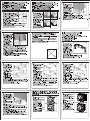
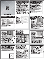
 XIGIVIAT EK
www.xigmatek. com
E-mail: [email protected] [email protected]
Installation Guide | Installationsanweisungen | 47 7% b—ILHA F |
Installation Guide Guide d'installation | Manual de instalación | Installationsguide |
Kurulum Кейбег! | Инструкция по монтажу | 5 В
[J Tear the protective film from the
bottom of Heat-sink, following the
arrow direction.
FZiehen Sie den Schutzfilm in
Richtung .
QE—FYY I MORI 4 LA
E KEIO HARD LE, 7
ня
ARetirez le film protecteur sur la = +=
base du dissipateur, suivez la E
x iy ===
fléche. =>
[Antes de realizar la instalacion, — x
(
Ш
ПА
(CC
li
(CAT
despegue la etiqueta protectora de
la parte inferior de la base del
disipador. Siga la dirección de la
flecha.
|
Ш
(
y
LL
— o щей =
FAvlägsna skyddsfilmen frân kontaktytan i pilens riktning.
FE Soëdutucu tabanindaki koruyucu filmi ok yônünde çekip cikarin.
F'OTopBUTe 3aLLUTHy10 NNeHKy cHU3y paguaTopa (ykasaHo cTpenkoï).
OS AAA ARRE о ИСВОВАУ ВАЛО ТМА ВА
Secure the moveable end of the
AM2/K8 clip onto the Retention
module and then screw it tight in a
clockwise direction. To release, turn
in the counter-clockwise direction.
mm
Ц
[CINach dem Einrasten des Clips in
der Nase des Retention Moduls
legen Sie den Bügel im
Uhrzeigesinn um. Um den Clip zu
lösen, legen Sie den Bügel
entgegen des Uhrzeigers wieder
um.
ШАМ2/К87 1) о 7 & |7 \— ВНЕ
отнес ОтУУамЕЙ
A—VITEET SH. MYSNTEHES
ZE. REE CER tE,
F]Sécurisez le dissipateur en déplaçant la partie déplaçable dans le sens horaire. Pour
relâcher, tournez dans le sens anti-horaire.
VU LAC TR AO LIT ASC LCI TI ARE LOL
И
ПОД
MAsegure el extremo móvil de la abrazadera AM2/K8 en el modulo de retención y, a
continuación, atornillelo en el sentido de las agujas del reloj hasta que quede bien
apretado. Para soltarlo, gire en sentido contrario a las agujas del reloj.
ASátt fast den rórliga delen av AM2/K8 installationsclipset pa CPU sockeln och skruva den
medsols fór att dra át den. Fór att lossa den skruva den motsols.
FAM2/K8 klipsindeki hareket edebilen ucu ¢ikinti olan yere sabitleyin ve oynamaz hale
getirmek igin ugta yer alan kolu saat yéniinde gevirin. Serbestlestirmek icin saat yoni
tersine çevirin.
FE] MpukpenuTe nogBHXHbl KOHEL| CK00bi AMD K8 k moaynio gepxaTers U NNOTHO 3ATAHNTE
винтом по часовой стрелке. Для освобождения, выверните против часовой стрелки.
ak EZ —SENIMANERM » IRKFEHEiB180° REE » ZAIRE -
AE Tryck ned láspinnarna diagonalt enligt ordningen (A-A & B-B). Tryck ned paren med
laspinnarna samtidigt tills kylflansen sitter fast ordentligt i moderkortet. For att lossa
kylflánsen vrids laspinnarna medsols till sin ursprungsposition.
MUclarda yer alan siyah plastikleri A ve B adimlarinda górúldugú gibi karsilikli olarak bastirip
anakarta geçirin. Her adimda ayni anda iki karsilikli ucu bastirin. Anakarttan sókmek icinse
bu siyah uçlari saat yônünde dôndürün.
[В шагах А и В затяните штифты по диагонали. Для надежной фиксации радиатора к мат.
плате нужно затягивать по два штифта одновременно. Для разборки нужно повернуть
каждый штифт по часовой стрелке, чтобы вернуть его в исходное положение. (
Ориентация для монтажа радиатора не указана, так как монтаж возможен с обеих
сторон.)
DÉARUHETN › ЭА > ВОК РВ - SXER TEMBER - EES LIERMTISTEE
BR + УМЕН RFR DS Reis HEH AER BI RARE -
(ZAR NEON » 207513027)
Precautions | VorsichtsmaBnahmen | Ef LM ¥%E | Précautions | Precauciones | Sákerhetsátgarder | Ónlemler | Mep»i npenocTopoxHocTV | EFISIA
41. Keep and store the product away from the reach of children.
2.Check the component list and condition of the product before installation. If there is any problem, contact
the shop where you purchased to get a replacement or refund.
3 .Xigmatek Co., Ltd. is not responsible for any damages due to external causes, including but not limited
to, improper use, problems with electrical power, accident, neglect, alteration, repair, improper
installation, and improper testing.
4.CPU and motherboard are subject to damage if the product in incorrectly installed.
4. Produkt kindersicher aufbewahren.
2.Priifen Sie vor der Installation die Komponentenliste und den Zustand des Produktes. Sollte es dabei ein
Problem gegen, wenden Sie sich an Ihren Händler zwecks Austauschs bzw. Rückerstattung.
3.Xigmatek Co., Ltd. haftet nicht für Beschädigungen durch äußere Einflüsse, einschließlich aber nicht
beschränkt auf unsachgemäßen Gebrauch, St gungsprobl ‚ Unfall, Nachlässigkeit,
Modifikationen, Reparaturen, unsachgemäße Installation und unsachgemäße Überprüfung.
4.Bei unsachgemäßer Installation können CPU und Motherboard beschädigt werden.
TM. BREEFHEOFOBEBIMINECAICHREFEIREEL TES,
2.8 Y 4417 DAMA NA HS UVEMPRRERMIELT<EEL, FED DOME, MEEICEXBLT
. EMERILESLTEDITC<EÉL,
3.Xigmatek Co., Ltd. IX, RIESE, ER OH, FB, HINE7TENIZL, UE, TEVE, T
EXEC, ERLENDICRE SNA LEN DESEEN LTEEEZÁNEES
As
4. MAIL <MYHAL1E, CPUBLU7 F—A— ПОЧВ БВ О ЖЗ.
41. Conservez et stockez le produit hors de portée des enfants.
2.Vérifiez la liste des composants et l'état du produit avant installation. En cas de probléme, contactez le
magasin ou vous l'avez acheté pour obtenir un remplacement ou un remboursement.
3 .Xigmatek Co., Ltd. n'est pas responsable des dégâts dus à des causes externes, y compris mais non
limité à, une mauvaise utilisation, des problèmes d'alimentation électrique, un accident, une négligence,
une modification, une réparation, une installation incorrecte ou un mauvais test.
4.Le CPU et le carte mère sont sujets à dégâts si le produit est mal installé.
41. Mantenga el producto almacenado fuera del alcance de los niños.
2.Revise la lista de componentes y la condición de los productos antes de la instalación. Si hay algún
problema contacte la tienda donde fue comprado para que le reemplacen el producto o le devuelvan su
dinero.
3.Xigmatek Co. Ltda. . no es responsable por daños debido a causas externas, como, uso indebido,
problemas con la corriente eléctrica, accidentes, negligencias, alteración, reparación, instalación
indebida y testeo indebido.
4.El procesador y placa madre pueden sufrir daño si el producto es indebidamente instalado.
ElApply the thermal grease on the
CPU evenly.
FVerteilen Sie die Wärmeleitpaste
gleichmäßig auf der CPU.
MCPUZB—7)L7 1) AH
o
[JAppliquez la pate thermique
uniformément sur le CPU.
MAplique la masilla térmica
uniformemente sobre la CPU.
FlApplicera ett jämt lager med
kylpasta.
CPU úzerine yeterince termal
macun sikin.
Ш!Равномерно нанесите термопасту на ЦПУ.
CHG EEE IZE7ECPU E»
Clip — Installation steps of Intel LGA 775 |
Clip — Installationsanweisungen fiir Intel LGA 775
Intel LGA775%X 5 97 ') y FER Y 4114551 |
Clip — Installation steps of Intel LGA 775 |
Pasos de instalación para Intel LGA 775 |
Installation av clips fór Intel LGA 775 |
Klips — Intel LGA 775 icin kurulum adimlari |
MoHTax cKko6b1 Intel LGA 775 |
Intel LGA 775(Push Pin)+1 El 2 27525 5508
AFasten the Clip and Clip screw onto
the bottom side of the heat-sink.
F]Legen Sie den Clip an und
verschrauben Sie diesen sauber an
der Unterseite des Heatsinks.
ШЕ- НУ УДОБНО Ума м
HD) yTEXRTTEET 5.
F]Fixer les attaches grâce aux vis sur
les bords de la base du dissipateur.
FAsegure el pasador LGA 775 у 105
tornillos del mismo en la parte
inferior del disipador
F]Skruva fast clipset i kylflänsens
botten.
aklipsleri górúuldudú gibi yerine
oturtun ve vidalari kullanarak
soÿutucu tabanuna sabitleyin.
ШВинтом скобы прикрепите скобу к нижней стороне радиатора.
OFERTES A RARAS EEE ©
Back plate -Installation steps of Intel LGA 775 / LGA 1366 (17) |
Clip — Installationsanweisungen fiir Intel LGA 775 |
Intel LGA775/LGA1366(i7)%iHi:7 37 7 7 L— HN Y 4117516 |
Back plate — Installation pour Socket Intel LGA 775/1366 (17) |
Pasos de instalación para Intel LGA 775/LGA 1366 (i7) |
Bakplat — installation fór Intel LGA 775 / LGA 1366 (i7) |
Arka plaka — Intel LGA 775 / LGA 1366 (i7) icin kurulum adimlan |
Монтаж монтажной пластины Intel LGA 775 / LGA 1366 (i7) |
LGA775 / LGA 1366(i7) SR 22325525785 |
| LGA775 |
F]Paste the Mylar on the back plate.
(LGA775 on the front side &
LGA1366 on the back side)
ESetzen Sie den MYLAR wie unten
beschrieben auf die Backplate.
(LGA775 Vorderseite & LGA1366
Rückseitig)
O743—%/$577L— MIRE Y
MZ. (EEITLGA775, Emili
LGA1366/= Xi LET)
F]Coller les protections sur le backplate. (Sur le dessus pour le LGA775 et sur le dessous
pour le LGA 1366)
AaPegue el adhesivo Mylar a la placa para 775 en el frente y para 1366 por detrás.
Aaklistra fast skyddsfilmen pá bakpláten (LGA775 pá framsidan 6 LGA1366 pá baksidan)
Mlizolasyon malzemesini arka plakaya yapistirin. (LGA 775 igin ón yúze, LGA 1366 için arka
yüze)
FHaxneñre maúnaposyio npoknaaky Ha MOHTaXHyl0 MNacTHHy. (LGA775 - Ha nepegHIoIo
сторону, а ССА1З66 - на заднюю сторону)
Ci HEALED BU BRMITE BRAY E(775)52(1366)miE
[11.F&rvara produkten utom rackhall fdr barn.
2 Kontrollera komponentlistan och produktens skick fôre installation. Om det ar nágra problem,
kontakta butiken dar du köpte den for att fa den utbytt eller fa pengarna tillbaka.
3.Xigmatek Co., Ltd. ansvarar inte fór eventuella externa skador, inklusive, men inte begránsat till,
felaktig användning, stromfórsóriningsproblem, olyckshándelse, omdómeslóshet, ándring,
reparation, felaktig installation eller felaktig testning.
4.CPU och moderkort kan skadas om produkten installeras felaktigt.
4.0rúnú gocuklarin ulasabilecegi yerlerden uzakta saklayin.
2.Montajdan ónce parca listesini ve úrúntin durumunu kontrol edin. Herhangi bir sorun varsa, yenisi
almak veya para iadesi için ürünü satin aldiginiz magaza ile temas kurun.C
3.Xigmatek Co., Ltd. hatali kullanim, elektrik sebekesi ile yaganan sorunlar, kaza, ihmal, tadilat,
onarim, hatalr kurulum ve uygun olmayan test dahil ancak bunlarla sinirlr olmamak kaydiyla higbir
hasardan sorumlu degildir.
4 .Ürün hatali sekilde kurulduysa islemci ve ana kart hasar gôrebilir.
El ‚Храните изделие в недоступном для детей месте.
2.Перед установкой проверьте список компонентов и состояние изделия. При наличии
проблем, обратитесь в магазин, где вы приобрели изделие, для замены или получения
возмещения.
3.Компания ХютаеК Со., На. не несет ответственности за ущерб или убытки, вызванные
внешними причинами, включая аварии, проблемы с электричеством, небрежное или
неправильное использование, модификации изделия, самостоятельный ремонт,
неправильная установка или неправильное тестирование изделия.
4.Неправильная установка изделия может привести к повреждению ЦПУ и материнской платы.
C1. EERE RFE El °
o
o
TINE > BAS > 1800 ~ 1238 > TEE 2 Z ENTES NIE ©
4 RARE SEAT Pi tré ani DIF RENE = > DIES ©
1
2.2 RAEE REI ANE1EMTES » AENA ATRE E AUTE Se A EE e RAR
. XigmatekX FIS TEMA NEAR - OFFER » THEEZ ER > THRE
Installation steps of AMD KS clip | Installationsanweisungen |
AMD K87 ') y FIN Y 11116 | Installation pour les clip AMD K8 |
Pasos de instalación para AMD AM2/K8 |
Installationsanvisning fór AMD K8 clip | AMD K8 klips igin kurulum adimlan |
Монтаж скобы АМО К8 | AMD K8i1El,2 273525525708
end of the slot at the bottom of
heat-sink to engage the Retention
module.
ALegen Sie den AMD Clip in die
Fúhrung des Coolers und
befestigen Sie diesen an den 2
Endpunkten / Nasen des AMD
Retention Moduls wie unten
beschrieben.
BCAPETITUavEda
—JLIZHY fT 5,
F]Placez les encoches de chaque
coté du support AM2/K8 afin de
yerlestirin.
зацепления модуля держателя.
FPlace AM2/K8 clip across the fixing
DAM2/K89 1) y7EE— FYYTIM
NUM
QU
|
Ш
ll
АА
TEER EERE ERA]
TERR
maintenir le dissipateur avec le module de rétention.
MAKER ARE » 19— MA ET CNERM >
Coloque la abrazadera AM25/K8 a través del extremo de fijación de la ranura que se
encuentra en la parte inferior del disipador para engranar el módulo de retención
AaPlacera AM2/KS clipset óver spáret pá kylflánsens botten fór att fixera fasthállningsmodulen.
FBadlanti modülünü hazir hale getirmek için AM2/K8 klipsini sogutucu altindaki yariga
[Установите скобу АМО К8 над крепежным концом гнезда снизу радиатора для
[[]Press the push-pin diagonally in
push-pin simultaneously each time
until the heat-sink can be securely
clamped on the main board. To
dismantle, turn each push-pin in a
clockwise direction to return to the
original position. (Orientation is not
provide for installing heat-sink,
which can be mounted on each
side.)
ADPrehe Sie die Push Pin's diagonal
wie in “A” und “B” beschrieben.
Drúcken Sie vorsichtig immer 2
PUSH PIN'S (wie unten
beschrieben) gleichzeitig, bis diese
step A and B. Press the two units of
В. ВОК ССС Ва,
o BENE ENTELÍ)
APressez les push-pin en diagonal A puis B. Pressez les 2 attaches simultanément jusqu'a
ce que le dissipateur soit fixé correctement à la carte mère. Pour démonter, tournez chaque
push-pin dans le sens horaire pour retourner a sa position initiale. (L'orientation n'est pas
fournie pour l'installation des dissipateurs qui peuvent être montés de différents angles.)
|
co
—
==
==
==
L =
ен ==
— "—
= |
Lo =
— я Lad =
EN
|
WI
A
O a LU TO
im Mainboard einrasten. Um diese zu sichern, drehen Sie diese wieder entgegen des
Uhrzeigersinns in die Originalposition. (Der Cooler kann in jeder Position montiert werden).
az 907 y E" 42 SIZA-BORIZEELES, 22071 Хх
A YR— FIIHES 5. RYSNTHBESEEFA ENT a EYELET, TO&EEEY
(E— H2291L AMA FIZE Y 1454147
A Presione el pasador en diagonal en los pasos A y B. Presione las dos unidades de los
pasadores simultáneamente hasta que el disipador quede perfectamente sujeto a la placa
base con la abrazadera. Para el desmontaje, gire cada uno de los pasadores en sentido
contrario a las agujas del reloj, para recuperar la posición original. (La orientación no se
proporciona para instalar el disipador, que se puede montar en cada lado)
[JAfter pasting the Mylar on the back
plate, aim and fix the back plate
onto the holes of the main board.
F]Nach dem Ansetzen des Mylars
legen Sie die Backplate auf die
Lochführungen des Mainboards
wie beschrieben.
OY43—EN997L— MIE Y
MITE. AL AR FORA
VI IL— FEWYURFIFEF®
| LGA1366 | 366
Après avoir coller les protections, ajustez et positionnez le back plate en face des trous de
la carte mère.
FDespués de colocar el adhesivo Mylar en la placa de 775/1366, apunte y fije la placa en
los agujeros de la placa base
FNär skyddsfilmen är applicerad monteras bakplâten fast i halen pa moderkortet.
MArka plakaya izolasyon malzemesini yapistirdiktan sonra deliklere uyacak biçimde anakart
arkasindaki yerine oturtun ve vidalayin.
[[IMocne Haknenku mannapoBoi NPoKiagKy Ha MOHTaXHYIO MacTUHY, COPUEHTUpYITe Y
закрепите монтажную пластину через отверстия в мат. плате.
OS RENNES NS ASS ERES >
Back plate — Installation steps of Intel LGA 775 / LGA 1366 (i7) / LGA 1156 (i5) |
Backplate — Installationsanweisungen fir Intel LGA 775 / LGA 1366 (i7) / LGA 1156 (i5) |
Intel LGA775/LGA1366 (17) ILGA1156(i5)Xiri:7 3 y 7 7 L— HR fT FIE |
Back plate — Installation pour Intel LGA 775 / LGA 1366 (i7) / LGA 1156 (i5) |
Back plate — Installation steps of Intel LGA 775 / LGA 1366 (i7) / LGA 1156 (i5) |
Bakplât - installation for Intel LGA 775 / LGA 1366 (i7) / LGA 1156 (i5)|
Arka plaka — Intel LGA 775 / LGA 1366 (i7) / LGA 1156 (i5) kurulum adimlar |
Монтаж монтажной пластины |т{е! ССА 775 / ССА 1366 (17) / LGA 1156 (i5) |
LGA775/ LGA1366(i7) | LGA1156(i5) S12 Zi |
a —— а
MAfter pasting the Mylar on the back plate, aim and fix the
back plate onto the holes of the main board.
ElNach dem Ansetzen des Mylars legen Sie die Backplate
auf die Lochführungen des Mainboards wie beschrieben. _
DY 5-ENYIFL MIBURITE RE, ХА УЖ в
FORIZNY 7 IL HEMUITEZ,
FlAprès avoir coller les protections, ajustez et positionnez
le back plate en face des trous de la carte mère.
[JAfter pasting the Mylar on the back plate, aim and fix the
back plate onto the holes of the main board.
FNär skyddsfilmen är applicerad monteras bakplâten fast i
halen pa moderkortet. .
FlArka plakaya izolasyon malzemesini yapistirdiktan sonra deliklere uyacak bigimde anakart
arkasindaki yerine oturtun ve vidalayin.
afocne Hakneñäku MañnapoBoñ npoxnagkn Ha MOHTaKHYIO MNaCTUHY, COPUEHTUPYIATE Y
закрепите монтажную пластину через отверстия в материнской плате.
CHG BE ZRH FRE TD TAS SAR BME EMR SE -
Clip - Installation steps of Intel LGA 775 / LGA 1156 (i5) / LGA 1366 (17) |
Clip - Installationsanweisungen fiir Intel LGA 775 / LGA 1156 (i5) / LGA 1366 (i7) |
Intel LGA775/LGA1156(i5)/LGA1366(i7)*11i:7 'J y FER Y 4t1+ENR |
Attaches — Etapes d'installation pour Intel LGA 775 / LGA 1156 (i5) / LGA 1366 (17) |
Pasos de instalación para Intel LGA 775/LGA 1156 (i5)/LGA 1366 (i7) |
Installation av clips fór Intel LGA 775 / LGA 1156 (i5) / LGA 1366 (i7) |
Klips - Intel LGA 775 / LGA 1366 (i7) / LGA 1156 (i5) kurulum adimlari |
MonTax ckobbl Intel LGA 775 / LGA 1156 (i5) / LGA 1366 (i7) |
Intel LGA 775 / LGA1156(i5) / LGA1366(i7)?+0.E 2 22325 55708 |
F]Fasten the Clip and Clip screw onto
the bottom side of the heat-sink.
ALegen Sie den Clip an und
verschrauben Sie diesen sauber an
der Unterseite des Heatsinks.
aE— h227706IZ)7 73
YU YTERUTHESS.
F]Fixez les attaches grâce aux vis sur
les cotés de la base du dissipateur.
[JFije el pasador y los tornillos en la
parte inferior del disipador
F]Skruva fast clipset i kylflansens
botten.
Aaklipsleri górúldúgú gibi yerine
oturtun ve vidalari kullanarak
sogutucu tabanuna sabitleyin.
Ш Винтом скобы прикрепите скобу к нижней стороне радиатора.
AEREA RANAS ENEE »
===
(i
Fasten the Spring-screw diagonally
in step A and B. Fasten the 2 units
of Spring-screw simultaneously (Do
not make full force at each time)
until the heat-sink can be securely
li
Il
.
Ш LENA
ili HEHE
fastened on the main board. SF
(Orientation is not provided for ~~ —
installing heat-sink, which can be =>>>> ===. I
mounted on each side.) === y —
r= | — |
[IBefestigen Sie die SPRING / IT | —]
SCREW diagonal in Schritt „A“ und
„B“ diagonal. Ziehen Sie 2 Units
der SPRING / SCREWS
gleichzeitig an (Verwenden Sie — :
hierbei nicht die volle Kraft um die al ee
Schrauben anzuziehen) bis der =
Heatsink sicher am Mainboard befestigt ist. (Der Cooler kann in jeder Position montiert
werden).
ARTY ITLIZA- BONE SCEELES - 20413514017 T (— EI
ERO LPDHEEDSRYMIEBNLSIZ) AL VR—FIZEEET о
(E— H229 LEO Y 1567 c REEAOEESIENTEET)
AFixez les vis a ressorts en diagonale A puis B. Fixez les deux vis simultanément (Ne fixer
pas complètement à chaque fois) jusqu’à ce que le dissipateur soit correctement fixé à la
carte mère.(L'orientation n’est pas fournie pour l'installation des dissipateurs qui peuvent
être montés de différents angles.)
]Fije los tornillos de muelle en diagonal en los pasos A y B. Fije las dos unidades de los
tornillos de muelle simultáneamente (no haga mucha fuerza en cada uno), hasta que el
disipador quede perfectamente sujeto a la placa base. (La orientación no se proporciona
para instalar el disipador, que se puede montar en cada lado)
Montera och skruva fjáderskruvarna diagonalt enligt ordningen (A-A 8: B-B). Skruva át varje
par med skruvar samtidigt (dra at varje skruv forsiktigt och i sma steg) tills kylflánsen sitter
fast ordentligt i moderkortet.
MUclarda yer alan siyah plastikleri A ve B adimlarinda gôrüldüdù gibi karsilikli olarak bastirip
anakarta gecirin. Her adimda ayni anda iki karsilikli ucu bastirin. (Her seferinde asiri güç
uygulamayin).
FEB шагах Аи В затяните пружинные винты по диагонали. Затягивайте по 2 пружинных
винта одновременно до надежного прикрепления к мат. плате (не перетягивайте винты
при попеременном затягивании). (Ориентация для монтажа радиатора не указана, так
как монтаж возможен с обеих сторон.)
OEA - BRISA > SRORRANE AE RENE » BERGER SILER
MASTER E > (ZARATE » НЛО ОЗ)
[J Take off the original RM from the
main board, then place the AMD
RM Base-Nut onto Main board.
HEntfernen Sie das originale
Retention Modul vom Mainboard,
und setzen Sie die AMD RM Base
Nut auf das Mainboard.
DAL AR FAA +
TIE 1—LERUAL
s AMDRMA—AH 4 FŒEAAY
R— FIZ Y 4175,
[IRetirer le module de rétention
original de la carte mére puis
placez le module de rétention AMD
Base-Nut sur la carte mére.
AaQuite el módulo de retención
original (zócalo) de la placa base,
después coloque el soporte del
modulo de retención en la placa
FMontera bort AMD Original modulen frân moderkortet och sätt dit de nya modulerna istället.
MAnakarttaki orijinal baglanti modülünü çikarin ve AMD badlanti modülünü yerine oturtun.
Снимите оригинальный модуль держателя с мат. платы и прикрепите сборку шайба/
опора держателя АМО к мат. плате.
GRAF HR CRYRMIZERST TS , IE #NAMD RM Base-Nut FX »
(Ат the holes of LGA775 clip to the
screw of AMD RM Base-Nut, then
fasten the M3 Spring-Nut to the
screw until the heat-sink is secured.
ESetzen Sie den Cooler mit den
Clips wie unten aufgeführt auf und
verschrauben diesen mit der M3
Spring-Nut bis dieser fest und
sicher sitzt.
ELGA7759 1) y J4 AMD RMXZ
+ HOLY 4, E— EH
2 9I1/M3X 7749 +TE
ET ©.
FAlignez les trous des attaches LGA
775 avec les vis du module de
rétention AMD Base-Nut, puis visser le rétention grâce aux vis M3 avec ressort.
МММ
NAN
TC RATAN
й
A
i
=
A
Coloque los agujeros del clip para LGA775 en los tornillos del soporte del modulo de
retención de AMD, entonces atornille las tuercas de muelle a los tornillos hasta que el
disipador este bien sujeto
Asikta in hálen pá LGA775 clippet sá skruven passar pá AMD RM Basen, fást sedan M3
Fjäderskruven tills kylaren sitter ordentligt fast.
ALGA 775 klipsinde yer alan delikleri AMD baglanti modúlúndeki vidalara denk gelecek
bicimde ayarlayin ve M3 yayli somunlari oturtup sikin.
[]CoBMecTHTe OTBEPCTHS CKOÔb! LGA775 c BHHTAMU cOopkH Wañ6a/onopa держателя AMD
и наверните пружинную шайбу МЗ на винты для закрепления радиатора.
CG 775H BALMER FRET HERR RR › РЗ НН МЗЗРДЕНЕЙЕ ЗЫ ИУ СЕЛИ Е > 162 ENZO
[If it is an AMD K8 main board, while
installation, place the PC-washer
onto the bottom of AMD RM
Base-Nut.
Sollte es sich um ein K8 Mainboard
handeln, setzen Sie bitte die
Abstandshalter während der
Installation unter die AMD RM
Base-Nut.
EJAMD K8 2 4 VA— FA 435
&. AMD ВМА м ВОН
7 ме Лт ЕЕ,
Si il s'agit d'une carte mére AMD
K8, placez le back plate de
rétention au dos de la carte mère
pendant la fixation du module de
retention.
[]Si se trata de una placa para AMD
K8, durante la instalación, coloque la arandela en los orificios de la base del soporte del
modulo de retención (zócalo)
Om det ár ett AMD K8 moderkort, placera en plastbricka pa botten av AMD RM modulen
nar du faster denna i moderkortet.
[JEger bu bir AMD K8 anakartsa kurulum sirasinda AMD baglanti modiilii altina contalari
yerlestirmeyi unutmayin.
]Mpu moHTaXe MaT.NJaTbi AMD K8 TpeOyetca ycTaHOBUTE CTaHHapTHeIE YNOPpbi CHI3y
сборки шайба/опора держателя АМРО.
[CIfEEFAMD K8AFIRY EHR IFILZARAMD RM Base-Nut H7IMMEPCAH -
Fan-Installation steps | Fan-Installation steps | 7 7 VEY H+FIE |
Ventilateur — Etapes d’installation | Pasos para instalar el ventilador |
Fan — Installation steps | Fan — Kurulum adimlari | Монтаж вентилятора |
Els 2225 |
ESecurely fix the anti-vibration rubbers onto
the fan.
E]Setzen Sie die Anti Vibrations Gummis an
den Lüfter an und ziehen diese durch die
Lochführungen
Ш 7 7 ЗЕНА Оо.
[JFixez correctement les gommes
anti-fibrations sur le ventilateur.
[JFije de forma segura las gomas
antivibración en el ventilador.
FMontera antivibrationsnipplarna pâ
fläkten.
E]Titresim kesici kauçuklari saÿlam biçimde
fana takin.
ШНадежно закрепите анти-вибрационные
подкладки на вентиляторе.
DÉLBSHÉER » EFE E
[[JUse Allen key to fasten the spring
screw in the clockwise direction and
in diagonal step.
E Verwenden Sie den Sechskant
Schlüssel um die LGA775/1366 clip
an die LGA775/1366 Backplate zu
befestigen / schrauben.
ША/\+ @& оС. 1СА775/13661)
Tviavy\)y FE LGATTS/
1366/3997 SL HDD
AUtilisez la clé Allen pour fixer
ensemble le clip Spring-screw et la
plaque arrière LGA775/1366.
MUse la llave Allen para fijar los 5
tornillos del clip LGA775/1366 a la placa trasera para el socket incluida.
FAnvänd Alley key for att fasta samman klamma och baksidesbricka.
AkKlipsleri ve arka panoyu birbirine baglamak icin alyan anahtarin: kullanin.
Для прикрепления монтажной скобы к монтажной плате используйте торцовый ключ.
DEREN °
Installationsanweisungen fiir AMD Retention Module |
Installationsanweisungen fiir AMD Retention Module |
AMD! 723 ED a—ILRRYAITFIE |
Etape d’installation du Module de rétention AMD. |
Pasos de la instalación del módulo de retención (zócalo) para AMD |
Installation av AMD RM Modulen |
AMD Baglanti Modülü kurulum adimlari |
Монтаж модуля держателя AMD |
AMD RM 277255588 |
F]Fasten the screw (from bottom to
top) onto AMD RM Base-Nut.
MSchrauben Sie die die Schraube
(von unten nach oben) in die AMD
RM Base-Nut.
[JAMD RMR—XR Fv FZ EEMN 5
ESA EZ TEEJAS
[JFixez les vis (du bas vers le haut)
dans la fixation AMD Base-Nut.
Fije los tornillos (de abajo a arriba)
en la base del módulo de retención
de AMD)
ASátt fast skruvarna (underifrán och
upp) i fasthallningsmodulerna.
[JAMD soket tabaninda yer alan alana vidalari (alttan ste dogru) takin.
[]3aTHHUTe BUHT (CHU3y BBEpX) 4epe3 rañky B OCHOBAHUU AMD.
CHR ME LIAEIZFAMD RM Base-Nut F ©
AFasten screws, which is originally
With original RM, and AMD RM
Base-Nut onto main board.
FSchrauben Sie die AMD BASE Nut
mit den Originalschrauben des
Retention Moduls fest.
Шх 4 УЖ- КЕЙ ОНО)
УуУа МЕН а —-Л РСС
ERZTAMDRMSA-A+y + %
3 5.
[JFasten screws, which is originally
with original RM, and AMD RM
Base-Nut onto main board.
[JFije los tornillos, los originales con
el modulo de retención original
(zócalo), y los del soporte del
modulo de retención en la placa
base.
ESkruva fast de nya modulerna pâ moderkortet med hjälp av skruvarna fran originalmodulen.
FlOrijinal baÿlanti modülüyle gelen vidalari kullanarak AMD baëlant1 modülünü anakarta
sabitleyin.
EMpukpernure cOopky Wañ6a/onopa держателя АМР к мат. плате оригинальными винтами
модуля держателя.
CIE AMDRERME ERY IR #4 SEMITEAMD RM Base-Nut I ©
[insert the Fan's anti-vibration rubber into
the heat-sink.
ASetzen Sie nun die Anti Vibrations
Gummis an den Cooler an und befestigen
Sie diese wie unten beschrieben.
Ш 7 7 УФН АЖ Е НУ У ЕН)
TTD.
EInsérez les gommes anti vibrations dans
le dissipateur.
Alnserte las gomas antivibración en el
disipador.
ASátt fast flákten ¡ kylflánsen genom att
fóra in antivibrationsnipplarna mellan
metallflänsen.
Bu kaucuklarin uçlarini soÿgutucudaki
uygun alana gegirin.
Вставьте анти-вибрационные
подкладки вентилятора в радиатор.
OE SERIES FAA BEAR ©