1
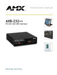
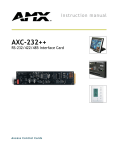
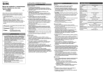
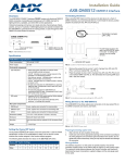
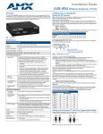
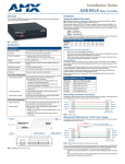
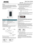
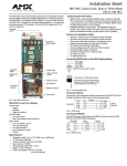
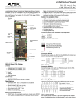
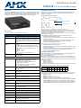
Installation Guide
AXB-232++ RS-232/422/485 Interface
Overview
Installation and Wiring
The AXB-232++ (FG5761-10) can serve as a conventional RS-232/422 control port, it is also
able to run its own Axcess application program – an exclusive AMX product feature. Source
specific programming, such as video switchers, laserdisc players and video codecs, can be
handled by the AXB-232++ to deliver a modular solution for system programming.
The AXB-232++ can be used as an independent RS-232/422/485-controlled interface by
setting the internal jumpers. Configure the communication parameters using the DIP
switches on the front panel.
Setting the Internal Jumpers
JP4
Internal jumper JP4
front
Internal jumper JP5
JP5
FIG. 2 Location of internal jumpers
Setting Jumper JP4 To Terminate RS-422 Input With 100 ohms
FIG. 1 AXB-232++
Specifications
The following table lists the specifications for the AXB-232++.
Specifications
Power
12 VDC @ 160 mA
Processor
On board 32-bit processor and 384K (of non-volatile memory)
run Axcess programs independent of the control system. This
relieves the AxLink bus and controller for the processing time
for controlling those devices. (Requires Axcess Version 3.0 or
higher.)
Asynchronous data
standards
• Baud rates - 300, 600, 1200. 2400, 4800, 9600, 19200 and
38400.
56400 is supported via the BAUDMED Send Command .
115200 is supported via the BAUDHIGH Send Command
(see the AXB-232++ Operation/Reference Guide for
details).
• Data bits - 7, 8, and 9
• Stop bits - 1 and 2
• Parity - None, Odd, Even, Mark and Space
Buffers
• 1KB input buffer
• 1KB AxLink buffer
Front Panel
AxLink LEDs
Green AxLink status indicator:
• Full-Off indicates no power is being received or the
controller is not functioning properly.
• One blink per second power is active and AxLink
communication is functioning.
• Full-On indicates power is active and AxLink data
communication is not functional.
RX LED (Red)
Blinks to indicate the AXB-232++ is receiving RS-232, RS422, or RS-485 data. The RX LED blinks even if the data being
received is incorrect.
TX LED (Red)
Blinks to indicate the AXB-232++ is sending RS-232, RS-422,
or RS-485 data.
DEVICE
DIP Switch
An 8-position DIP switch used to set the device number for the
AXB-232++.
RS232/422
DIP Switch
An 8-position DIP switch used to set the communication
parameters for the RS-232/422 device.
Rear Panel
Hardware handshaking
connector
An RTS/CTS data connector that can be wired for hardware
handshaking if called for by the controlled device (4-pin male).
RS422/232 connector
A captive-wire connector wired for RS-422/232 data control
(8-pin male).
AxLink connector
Receives power and data via the AxLink bus and AxLink system controller 4-pin male).
Internal Jumpers
Sets differential input termination and enables RS-485 output.
Supports
XON/XOFF software and hardware handshaking
Dimensions (HWD)
1.5" x 5.5" x 5.5" (3.81 cm x 13.97 cm x 13.97 cm)
Weight
1.1 lbs. (498.95 g)
Enclosure
Metal with black matte finish
Included
Accessories
• AxLink connector (4-pin female)
• Phoenix connector (8-pin male)
Other AMX
Equipment
• CC-232 Control Cable
• AC-RK Accessory Rack Kit
Terminating a device involves installing a 100 ohm line terminator, this is typically used to
achieve better communication and signal integrity. You will want to terminate when the
communication is at a high data rate or over a long distance.
Termination can be harmful because it increases the current in the line, and more radiation
that could interfere with signals.
Jumper JP4 places 100 Ohms termination across RS422 receive data pins 5 & 6:
1.
Disconnect the RS-232/422/485 connectors.
2.
Unscrew the two screws on the rear panel to remove the panel, and slide the circuit
board out of the enclosure.
3.
Locate the JP4 jumper and install the jumper in the 'ON' position (default = OFF).
4.
Slide the circuit board back into the enclosure and replace the rear panel.
5.
Reconnect the RS-232/422/485 connectors.
Setting Jumper JP5 To Set The RS-422 Port for RS-485 Use
1.
2.
3.
4.
5.
Disconnect the RS-232/422/485 connectors.
Unscrew the two screws on the rear panel to remove the panel, and slide the circuit
board out of the enclosure.
Locate the JP5 jumper and set jumper JP5 to the ON position (default setting is OFF).
Slide the circuit board back into the enclosure and replace the rear panel.
Reconnect the RS-232/422/485 connectors.
Setting the DIP Switches
Note: Use the DIPSwitch 2.0 application available for free download from AMX to quickly
figure out DIP Switch settings for all types of DIP Switches.
Setting the DEVICE DIP switch
Set the device number on DEVICE DIP switch, located on the front of the AXB-232++. The
device can be 1 of the 255 devices in an Axcess control system. The device number must
match the device assignment in the Axcess program. Device numbers are assigned into the
following three segments:
• Cards 1 through 95
• Boxes 96 through 127
• Panels 128 through 255
Set the device number by setting the device DIP switches. The device number is the total of
all of the switches in the ON position, and take effect by cycling the power.
DEVICE DIP Switch Settings
Position
1
2
3
4
5
6
7
8
Value
1
2
4
8
16
32
64
128
Setting the RS-232/422 DIP switch
Set the stop bits, data bits, parity, and baud rate on the RS-232/422 DIP switch, located on
the front panel. The AXB-232++ supports the following asynchronous data standards:
• Stop bits 1 and 2
• Data bits 7, 8, and 9
• Parity None, Odd, Even, Mark, and Space
• Baud rates 300, 600, 1,200, 2,400, 4,800, 9,600, 19,200 and 38,400.
57,600 is achieved by setting the DIP switch to 300 baud, and using the ’BAUDMED’
SEND_COMMAND (see the AXB-232++ Operation/Reference Guide for details).
115,200 is achieved by setting the DIP switch to 300 baud, and using the ’BAUDHIGH’
SEND_COMMAND (see the AXB-232++ Operation/Reference Guide for details).
The table below shows the RS-232/422 DIP switch numbers, functions, and their
corresponding values.
Using RS-232
When communicating via RS-232, connect the wiring as shown in FIG. 5.
RS-232/422 DIP Switch Settings
Switch
1
2
Function
Stop Bits
Data Bits
Setting
Off
Off
Value
2 bits
7 bits
On
On
1 bit
8 bits
3
4
5
6
Parity
Off
Off
Off
Off
Off
Off
On
On
On
Off
Off
Off
On
Off
Off
On
Off
On
On
On
On
Off
Off
On
Off
On
On
None
On
Using Hardware Handshaking
When the controlled device requires hardware handshaking, connect the wiring as shown in
FIG. 6.
On
On
1
AXB-232++ 2
3
4
38,400
To connect the wiring into a captive-wire connector:
1.
Strip 1/4 inch off the wire insulation for all four wires and tin 2/3 of the exposed wire.
2.
Insert each wire into the appropriate captive-wire connector up to the insulation.
3.
Tighten the captive screws to secure the fit in the connector.
Note: If the device is using a separate power supply, do not connect the power wiring from
the AXB-232++ to that device.
The interface requires a 12 VDC power to operate properly. The interface uses a PSN2.8
power supply. The Central Controller supplies power via the AxLink cable or external 12 VDC
power supply.
The maximum wiring distance between the Central Controller and interface is determined by
power consumption, supplied voltage, and the wire gauge used for the cable.
The table below lists wire sizes and maximum lengths allowable between the AXB-RS232++
and Central Controller.
The maximum wiring lengths for using AxLink power are based on a minimum of 13.5 volts
available at the Central Controller’s power supply.
GND
RX
TX
+12V
RX RX +
TX TX +
AXB232++
20 AWG
464.11 feet (141.46 m)
22 AWG
289.35 feet (88.19 m)
24 AWG
182.39 feet (55.59 m)
RX+
When communicating via RS-485, connect the wiring as shown in FIG. 8.
GND
RX
TX
+12V
RX RX +
TX TX +
Device
FIG. 8 RS-485 wiring
Rack-mounting the AXB-232++ (optional)
Connect the AxLink wiring to the connector on the AXB-232++ as shown in FIG. 3. i
PWR
PWR
AXP
AXP
AXM
AXM
GND
GND
System
Using AxLink and External Power Supply
Connect the AxLink and power wiring to the connector on the AXB-232++ as shown in
FIG. 4.
PWR
PWR
AXP
AXP
AXM
AXM
GND
GND
+12 VDC
GND
FIG. 4 AxLink bus and +12 VDC power wiring
To rack-mount the AXB-232++ into the optional AC-RK Accessory Rack Kit:
1.
Remove any connected power, and AxLink and RS-232 connectors from the rear
panel.
2.
Remove the 2 screws on the front panel, and remove the front panel and the space
bracket behind the panel.
3.
Place the unit in the appropriate opening in the AC-RK.
4.
Place the front panel of the AXB-232++ on the front of the rack, over the unit.
5.
Fasten the front panel to the rack and unit with the two screws you removed.
Replacing the Lithium Batteries
FIG. 3 AxLink bus and +12 VDC power wiring
AxLink
Device
Using RS-485
AXB232++
Using AxLink
AxLink
GND
TXTX+
RX-
FIG. 7 RS-422 wiring
Wiring Guidelines at 160 mA
Maximum Wiring Length
Device
When communicating via RS-422, connect the wiring as shown in FIG. 7.
Wiring Guidelines
733.57 feet (223.59 m)
RTS
CTS
Using RS-422
Preparing Captive Wires
18 AWG
CTS
RTS
FIG. 6 Hardware handshaking wiring
On
Wiring Devices to the AXB-232++
Wire Size
TX
On
19,200
On
Device
RX
FIG. 5 RS-232 wiring
Off
9,600
Odd
On
On
GND
TX TX +
Off
4,800
Even
Off
On
GND
RX
TX
+12V
RX RX +
Off
2,400
Mark
On
Off
1,200
Unused
Off
Off
600
Unused
On
Off
AXB232++
300
Unused
Off
8
Baud Rates
Unused
On
7
System
Power Supply
The AXB-232++’s lithium batteries have a life of approximately 5 years to protect its memory.
When DC power is on, the batteries are not used. When you install the AXB-232++, record
the date the batteries should be replaced.
Note: There is a danger of explosion if you replace the batteries incorrectly. Replace
batteries with the same or equivalent type recommended by the manufacturer. Dispose of
the used batteries according to the manufacturer’s instructions. Never recharge,
disassemble, or heat batteries above 212°F (100°C). Never solder directly to the batteries or
expose the contents of the batteries to water.
Before removing the lithium batteries, contact your dealer and verify that they have a current
copy of your program to avoid an inadvertent loss of data and prevent an unnecessary
service outage.
1.
Discharge the static electricity from your body.
2.
Unplug the 2-pin power connector and any other connectors.
3.
Remove the 2 screws on the front panel, remove the front panel, and slide the circuit
board out of the enclosure.
4.
Carefully slide each battery out of its socket, and insert the new battery.
5.
Slide the circuit board back into place, replace the front panel and refasten the screws.
6.
Reconnect any connectors that you removed.
Additional Documentation
Refer to the AXB-232++ Operation/Reference Guide for programming information.
For full warranty information, refer to the AMX Instruction Manual(s) associated with your Product(s).
5/12
©2012 AMX. All rights reserved. AMX and the AMX logo are registered trademarks of AMX.
AMX reserves the right to alter specifications without notice at any time.
3000 RESEARCH DRIVE, RICHARDSON, TX 75082 • 800.222.0193 • fax 469.624.7153 • technical support 800.932.6993 • www.amx.com
93-5761-10
REV: A