1
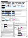
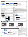
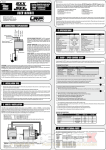
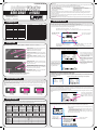
© LRP electronic GmbH 2010 LA00048 Dear Customer, thank you for your trust in this LRP product. By purchasing a LRP Pulsar Touch, you have chosen a high-performance product which has the latest technology incorporated including the following High-Tech features: • Professional Multi-Function System (Charge, Discharge, Cycle, Balance, Motor/ESC/Servo Check) • up to 12.0A Charge Current • up to 20.0A discharge current (+ 35A Pulse Discharge) • LiPo • LiFePo • NiMH • NiCd • Integrated Balancer for 2S-4S Lixx batteries • • Touchscreen Graphics LCD Display • 5 User Profile Memories • 25-Year Warranty • Multi-Protection-System user guide - #41555 Please read the following instructions carefully before you start using your charger. This user guide contains important notes for the installation, the safety, the use and the maintenance of this product. Thus protecting yourself and avoid damages of the product. Proceed according to the user guide in order to understand your charger better. Please take your time as you will have much more joy with your product if you know it exactly. This user manual shall be kept in a safe place. If another customer is using this product, this manual has to be handed out together with it. LRP electronic GmbH Wilhelm-Enssle-Str. 132-134 73630 Remshalden, Germany [email protected] www.LRP.cc Touchscreen usage technical data Dimensions Weight Input Voltage Charging Capability [mm] [g] [DC] LiPo/LiFePo NiMH/NiCd Charge Current [A] Trickle Current [A] Delta Peak [mV] Integrated High-Performance Balancer Storage Charge Mode Discharge Current [A] Discharge LiPo/LiFePo Cut-Off Voltage NiMH/NiCd 1585x172x68 720 11-15V 1 - 4 cells 1 - 10cells 0.1 - 12.0 0 -0.55 1 - 200 yes, 2S - 4S yes 0.1 -20.0 (+ 35 Pulse) 2.0 - 4.2V/cell 0.1- 1.3V/cell Autostart Timer Cycle Mode User Profile Memory Graphical Touchscreen LCD Acoustic Signal Type Finish Melody Multi-Protection-System DC Input Connection Output Connection Brushless Motor Sensor Port RX Generator (ESC + Servo Check) Voltage Calibration Mode USB Connection yes, 0-99min yes, adjustable 5 yes, blue backlit Buzzer adjustable yes 4.0mm connector 4.0mm jacket yes yes yes yes As known from LRP, the programme structure is logical and intuitive, therefore most users can familiarise with the usage and functions without even reading the manual, but it is obviously strongly recommended to read this manual in order to achieve maximum performance from the PulsarTouch and make best use of all of it‘s great features. You can either use your finger or the included plastic pen to use the touchscreen, make sure you only use very light pressure to activate the functions as too high pressure may damage the display! Press briefly to jump to next profile (P1 > P2 > P3 > P4 > P5 > P1 ...). Keep pressed to enter „Profile Name“ menu, which allows renaming of the choosen profile (see below). P1 PROFILE NAME press arrow to scroll to the „leftt“ (e.g. previous function) . press arrow to scroll to the „right“ (e.g. next function) LINEAR CHARGE Specifications subject to change without notice. SETUP START connections press „SETUP“ to change the settings of this function (in this case the function is LINEAR CHARGE). Input Connection (backside of charger, no picture): connect your Pulsar Touch to a suitable DC powersupply with 11-15V output voltage and a minimum of 12.0A output current. Caution: Be careful with correct polarity! Output Jacket: connect battery to be charged to the 4.0mm jacket, using supplied charge wires. Caution: Be careful with correct polarity! Adjusting the settings and hoping through multi-page menu: P1 CHARGE Chg Mode : Current : DPeak : Trickle : Safety Time: Balancer Connector: high-performance integrated Lixx balancer for 2S to 4S packs using EHR balancing connector. Temperature Sensor (optional): connect the optional temperature probe to measure battery temperature. USB Connection: connect to PCB using the supplied USB-cable. To be used for upcoming firmware updates and PC software. Brushless Motor Sensor Port: a fantastic feature which allows you to check your brushless motors sensors and even measure motor rpm! In combination with the built-in receiver simulator port. The logo (LINEAR CHARGE in this case) indicates which function is pre-selected. Press „START“ or center symbol to start the function. [1/2] X Linear 4.0A 20mV Off 90min NEXT as [1/2] and [2/2] indicate in headline, there is a multipage menu with more then one screen. You can hop through the pages by pressing „NEXT“ button. SET P1 CHARGE Cut-Temp : [2/2] X 55°C NEXT after accessing the menu with „SETUP“ you can select the value which you may access that value directly by pressing with your finger or pen or by pressing „SET“ button. Once this line is shown inversed (black background), you can then change that value using the up/down arrown keys. You may leave the „SETUP“ menu again at any time, and the current values will be stored, by pressing X in upper/right corner SET RX Simulator Port: you can even check speedcontrols and servo‘s for correct function! Hidden buttons and how to make them visible again? 15A Fuse: input fuse for protection, only replace with another 15A fuse (blue colored housing) and no other types as these would not offer protection or correct function! To allow more clean screen and more useful information, the buttons will be hidden during many active functions. Simply touching the screen anywhere will make the buttons visible again. After a short while of no use of the screen, the buttons will hide again automatically. Buttons Hidden: balancER Connection The Pulsar Touch contains an integrated competition balancer for 2S to 4S LiPo- and LiFePo-batteries using EHR balancing connector. Please refer to drawing (also like that on charger) for correct polarity, basically minus (black wire) is always on the far right side of the plug as shown on drawing. The balancer equalises the cells, during charge- and balance-function, which results in higher performance and higher cyclelife. Caution: Avoid incorrect connection as in the worst case this may result in damage to the battery and/or charger! Connection Example 4S: Cell 2 Cell 1 Black Minus Cell 3 Cell 2 Cell 1 Black Minus Connection Example 3S: Buttons visible again (after briefly touching screen anywhere): 02m30s 250mAh 6.00A 7.82V 0.0mΩ 0.0°C _XXXX CHARGE Capacity Current Voltage Resistance Temperature 02m30s 250mAh 6.00A 7.82V 0.0mΩ 0.0°C NEXT STOP How to adjust the current on the fly? As known by LRP, the Pulsar Touch‘s current (charge or discharge) can be adjusted during use. Touch the current value on the screen, the characters will become inverse (black background) and then use the up/down arrow keys to adjust the current to your desired value without interrupting the active process. Important: This change is not saved in memory, the next time you use this function the settings from the memory will be used. _XXXX CHARGE Capacity Current Voltage Resistance Temperature Cell 4 Cell 3 Cell 2 Cell 1 Black Minus Connection Example 2S: _XXXX CHARGE Capacity Current Voltage Resistance Temperature factory defaults 02m30s 250mAh 6.00A 7.98V 0.0mΩ 0.0°C NEXT Touch current, characters will become inverse (black background)Now use up/down arrow keys to adjust current to your desired value. STOP The Pulsar Touch comes with 5 pre-set user profiles, but you can also alter those and prepare 5 individual user profiles and even name them as you like. This means you can customize 5 personal charge profiles individually and store them for later use. The active profile P1 to P5 and it‘s name is indicated in the headline of the main menu. User Profile CHARGE SETTINGS: Chg Mode Current Pack Volt D-Peak Trickle Safety Time P1 P2 P3 P4 P5 LiPo 6.0A 7.4V / 2S LiFe 6.0A 6.6V / 2S LiPo 6.0A 3.7V / 1S LiPo 2.0A 11.1V / 3S Linear 4.0A 120min 40°C 120min 40°C 180min 40°C 20.0A 6.6V / 2S 2.2V/C 60°C 20.0A 3.7V / 1S 3.2V/C 60°C 2.0A 11.1V / 3S 3.2V/C 60°C 10.0A 2S-LiFe 6A/20A 1S-LiPo 6A/20A 1000 2000 On 15sec 1 7 °C 3S-LiPo 2A/2A Linear 4A/10A 120min 40°C DISCHARGE SETTINGS: Current 20.0A Pack Volt 7.4V / 2S Cutoff Volt 3.2V/C Cut-Temp 60°C OTHER SETTINGS: Profile Name 2S-LiPo 6A/20A Signal Min Signal Max Button Sound Finish Sound Finish Melody LCD Contrast Temp Scale Tip: You can always reset to above factory default settings under „CONFIG“ function (see separate box). 20mV Off 90min 55°C How to change the profile names? Keep headline pressed in main menu, this brings you into the function to alter the active profiles name. P1 PROFILE NAME You can change the name in several ways, pick the method you feel most comfortable with. 1. straight indicate/write by touching the characters one after the other. 2. hop through the characters by using the right key and confirm the selected character by using the „√“ key. . LINEAR CHARGE SETUP You confirm and leave this setting by either pressing „X“ symbol in upper right corner or by pressing „OK“ key. START 5.4V 70°C indicates which character in headline you have selected for changing P1 PROFILE NAME ▲ ABCDEFHIJKLMNOPQR STUVWXYZabcdefghi jklmnopqrstuvwxyz 0123456789-._’#+/ V DEL OK X indicates new character you have selected. programme structure - SETUP After powering up your Pulsar Touch you are in the main menu where you can scroll through all functions (Charge / Discharge / Cycle / Balance / View Last Data / Config / Motor-ESC-Servo) and either start the required process by press „START“ button or access the particular functions setup by pressing „SETUP“. All the functions and our recommendations are explained in detail on next pages. P1 PROFILE NAME . P1 PROFILE NAME START P1 CHARGE Chg Mode : Current : DPeak : Trickle : Safety Time: SETUP [1/2] X Linear 4.0A 20mV Off 90min NEXT . P1 PROFILE NAME CYCLE SETUP START P1 DISCHARGE X Current : 20.0A Pack.Volt : 7.4V/2S Cutoff.V. : 3.2V/C Cut-Temp : 50°C . P1 PROFILE NAME VIEW P1 CYCLE X Direction : CD Cycles : 1 Chg Delay : 10min Dischg Delay: 10min SET SET . P1 PROFILE NAME VIEW LAST DATA BALANCE START START P1 BALANCE [1/2] X 1s:0.000V 3s:0.000V ▼4s:0.000V P1 PROFILE NAME CONFIG P1 DATA VIEW [1/3] X Input : 0.000V Output : 0.000V Batt.Temp : 0.0°C Max Temp : 0.0°C Resistance : 0.0mΩ ▲2s:0.000V . SETUP P1 CONFIG [1/2] X Button Sound : ON Finish Sound :15sec Finish Melody: 1 LCD Contrast : 10 Temp Scale : °C START MOTOR-ESC-SERVO X Signal Min : 1100 Signal Max : 1900 NEXT NEXT . MOTOR-ESC-SERVO SETUP START Gap 0.000V SET P1 CHARGE Cut-Temp : P1 PROFILE NAME DISCHARGE LINEAR CHARGE SETUP . SET [2/2] X 55°C NEXT SET charge Process The Pulsar Touch can charge LiPo, LiFePo, NiMH and NiCd batteriesand incorporates the designated charge algorithms for each particular cell type for best performance, reliability and safety with up to 12.0A charge current. Please always follow your battery manufacturers recommendations for maximum allowed charge current and make sure you always use the correct „Chg Mode“ setting for the battery you want to charge, as wrong setting may result in damage to the battery! P1 PROFILE NAME . P1 PROFILE NAME LINEAR CHARGE SETUP P1 PROFILE NAME .. LIFE CHARGE LIPO CHARGE START SETUP CHARGE START X Chg Mode : Linear Pack.Volt : Auto Current : 4.0A DPeak : 20mV Trickle : Off Cut-Temp : °C CHARGE START X Autostart : 0min Storage Charge XXXX : 0.0X SETUP START CHARGE START Chg Mode Pack.Volt Current Cut-Temp .. X Chg Mode Pack.Volt Current Cut-Temp .. Depending on which profile you have choosen or if you altered the settings under „SETUP“ the designated charge type „LINEAR“, „LIPO“, „LIFE“ or „STEP“ will be indicated on the screen. STEP CHARGE START CHARGE START : LiPo : 7.4V/2s : 6.0A : 40°C P1 PROFILE NAME SETUP X : LiFe : 6.6V/2s : 6.0A : 40°C START CHARGE START Current 0.0 0.0 Capacity 0.0 0.0 0.0 0.0 X 0.0 0.0 0.0 0.0 After starting the operation by pressing „START“ button or cell symbol (both works!) the choosen settings will be indicated for you again to avoid incorrect settings for the battery you intend to charge. You can cancel the operation, and return to main menu, by pressing the „X“ symbol in the upper right corner. Autostart: This handy feature lets you preselect when you want to start charging your battery with the Pulsar Touch. The Autostart Timer is adjustable from 0 - 99min. If you stay in the „Autostart Display“ for longer then 30sec without setting a value, the charging process will start automatically. Storage Charge: Never store your batteries completely empty as this will harm them and lower their performance. Due to this fact, the Pulsar Touch features a „Storage charge“ mode. With this function, you can set a fixed voltage (vor Lixx batteries) or fixed capacity (for Nixx batteries) value and the battery will be partially charged or discharged (in case of Lixx) exactly to this level. Thus you can always perfectly prepare your battery for storage, if you want to store them over a longer period of time. Our recommendations: NiMH/NiCd: 50% of nominal capacity *** LiPo: 3.8V/cell *** LiFePo: 3.4V/cell START Chg Mode Time elapsed since start of charge AUTOSTART TIMER _ Time to Start 00m00s CHECK STATUS: BATTERY......ok Connection...ok STOP START time until charging starts, you can skip and start immediately by pressing „START“ or you can return to the main menu by pressing „STOP“. your charger checks if all connections and the battery itself are ok and if charge process can be started. _XXXX CHARGE Capacity Current Voltage Resistance Temperature NEXT 02m30s 250mAh 6.00A 7.82V 0.0mΩ 0.0°C STOP Charge capcacity Charge current (adjustable during charging!) Actual pack voltage Internal resistance of your pack during charging Temperature of your pack (optional with sensor) CHARGE - explanations: CHARGE - further screens: LiPo/LiFe pack voltage: The packs rated voltage for LiPo/LiFePo batteries must be set according to the packs rating. During running charge process there is additional information available, by pressing „NEXT“ button you may access those. The available screens are (you jump to next by pressing „NEXT“ again): - Voltage of each cell in pack (if balancer is used!), for description see section „Balancer“. - Internal resistance of each cell in pack (if balancer is used!), for description see section „Balancer“. - Data View screens, , for description see section „View Last Data“. Linear Charge: the most common method for NiMH/NiCd cells, a constant current from beginning to end of charge process, the easiest method for charging. Step Charge: should only be used by experienced racers and only for NiMH cells! You may select special charging methods for 1st to 3rd step (4th step is fixed to linear!): _ = Linear charge ∏ = Impulse charges with 1.5x of selected current for short periods. ∐ = Reflex - charges with short discharge spikes every few seconds. P1 CHARGE [1/2] X Chg Mode : Step 1st: _ _ 1.0A/0.1Ah 2nd: _ _ 4.0A/1.0Ah 3rd: _ _ 8.0A/4.0Ah 4th: 4.0A/5.5Ah NEXT P1 CHARGE DPeak Trickle Safety Time Cut-Temp NEXT SET : : : : [2/2] X 15mV Off 120min 50°C SET Current and Capacity for 1st step, should be a low value for current and capacity (1.0A and 0.1Ah is our suggestion) 2nd step current can be higher, we suggest to charge for 25% of batteries nominal capacity with 1C charge. 3rd step, this current you can set fairly high (up to 2C charge rate), only charge to 75% of batteries nominal capacity with this rate. 4th step, use lower current again to end of charge for accurate peak detection and best performace. Set capacity for this step to ~110% of nominal capacity. Same settings on the second screen of „Step Charging“ as for normal linear charge of NiMH/NiCd cells! Charge Algorithms: the Pulsar Touch contains high-accuracy charge profiles for each type of battery, make sure you always use the correct „Chg Mode“ setting for the battery you want to charge, as wrong setting may result in damage to the battery! LiPo/LiFePo NiMH/NiCd charging using the CC/CV-charging method. With this charging method, the battery gets charged with a constant current first. As soon as the battery voltage reaches the max. allowed charging voltage per cell (for example, LiPo 4.2V and LiFePo 3.7V), the charger automatically reduces the charging current till the battery is fully charged. view last data The Pulsar Touch allows to view the stored data of the last 11 processes (charge, discharge or cycle). You can access the same data also during any operation (charge, discharge, etc) by pressing the „NEXT“ button, this means you can view the stored data from a previous operation during actual use! The last operation is always the memory „0“. P1 PROFILE NAME .. VIEW LAST DATA START P1 DATA VIEW [1/3] X Input : 0.000V Output : 0.000V Batt.Temp : 0.0℃ Max Temp : 0.0℃ Resistance : 0.0mΩ Charger‘s input voltage Voltage at output socket Actual battery temperature Maximum temperature which battery reached Internal resistance of battery NEXT using up/down arrow keys allows you to scroll through the stored 11 cycle data‘s (number is indicated in headline, 0 - 10). CYCLE DATA 0 [2/3] X charge time peak voltage at end of charge charge capacity -Chg000m00s 0.000Vp 000.0Ah -Dischg000m00s 0.000Va 000.0Ah discharge time average voltage during discharging discharged capacity NEXT charging with constant current (Linear- or Step-Mode!) + delta-peak detection. This is the most popular charging method for NiMH/NiCd-batteries in competition GRAPH VIEW [3/3] X 0:00:00 0.00V Gr=V here you can view the charge or discharge curve of the selected data and can even select different curves, zoom into the curve, etc as explained below (this is only useful for experienced users!) Charge Current: The charge current can be set from 0.1 to 12.0A, for racing cells (Sub-C size) in LiPo, LiFe and NiMH technology you can usually use 1.5C charge rate (e.g. 7.5A for a 5000mAh pack) with no problem. However, for lower grade cells and receiver-/transmitter battery packs you should use a lower charge current and should follow your battery manufacturer‘s recommmendations. 0.000Vc 0.000V =A Delta Peak: With NiMH/NiCd-batteries, you only obtain the optimum battery performance by slightly „overcharging“ the battery. In real terms, it will not be overcharged, but charged to an optimum level. The battery voltage drops at the end of the charging process (delta). The size of the drop (delta peak) is adjustable in the range between 1 - 200mV. The higher the value, the hotter the battery will be at the end of the charge. We recommend to start with the works-default settings. Note: The adjustable Delta-Peak value applies to the whole battery pack and not to one single cell! Trickle Charge: This current, which flows after delta peak cutoff, is adjustable from 0.0 - 0.5A to achieve the highest possible voltage for NiCd cells. Set this function to „Off“ for NiMH cells. Alternatively you can use the Auto Trickle Function for an automatic Trickle Charge setup. Connections: make sure you use high-quality wire and connectors for maximum accuracy, a poor connector or poor wire may create heat and affect the accuracy, Temperature Sensor: there is an optional temperature sensor available, so you can monitor the battery temperature during charging and discharging. As it‘s normally not required for most users, we didn‘t include it with the charger as it would have only increased cost for everyone. When no sensor is connected, display will indicate „0.0°C“ 0X DATA VIEW [3/3] X 0:00:00 0.00V Gr=V press curve to activate measurement line, which can be moved with up/ down buttons. middle point of Y-axis you can display three different parameters as a curve and you hop through them by pressing circled area briefly (V = voltage, I = current, T = temperature increase or decrease the marked (inversed/ black background) value. 0.000Vc 0.000V =A Resolution of Y-axis (voltage, current or temperature), if „=A“ it‘s on automatic setting 0X Zoom Level of X-Axis (Time, horizontal): AT = Automatic Zoom 1x to 43x = Manual Zoom dischargE The adjustable high-performance discharge circuit (0.1 to 20.0A + 35A Pulse discharge) can be used for 1-14 cell NiMH/NiCd- and 1-4 cell Lixx-packs. The Pulsar Touch informs you about all the data relating to the battery pack, e.g. discharge time, capacity, average voltage and internal resistance. By discharging your battery pack on the Pulsar Touch after use, you obtain vital information about remaining capacity for optimizing your motor or gear ratio for the next run. This also maintains your battery packs in good condition. P1 PROFILE NAME . Discharge screen: DISCHARGE START DISCHARGE SETUP Current Pack.Volt Cutoff V. Cut-Temp START X _ DISCHARGE Capacity Current Voltage Avg.volt Resistance CHECK STATUS: : 20.0A : 7.4V/2s : 3.2V : 55°C BATTERY......ok Connection...ok the choosen settings will be indicated to avoid incorrect settings for the battery you want to discharge. Cancel the operation by pressing X in upper right corner! your charger checks if all connections and the battery itself are ok and if discharge process can be started. Time elapsed since start of discharge 00m05s 0030mAh 20.00A 07.50V 07.68V 0.0mΩ NEXT NEXT Discharge capcacity Discharge current Actual pack voltage Average voltage of your pack during discharging STOP Internal resistance of your pack DISCHARGE - explanations: DISCHARGE - further screens: Discharge Current: The discharge current can be set from 0.1 - 20.0A and 35A pulse. If not otherwise specified by the During running discharge process there is additional information available, by pressing „NEXT“ button you may access those. The available screens are (you jump to next by pressing „NEXT“ again): - Voltage of each cell in pack (if balancer is used!), for description see section „Balancer“. - Internal resistance of each cell in pack (if balancer is used!), for description see section „Balancer“. - Data View screens, , for description see section „View Last Data“. battery manufacturer, the max. discharge current can be set to 20.0A for racing cells (Sub-C size) in LiPo, LiFe and NiMH technology. However, lower grade cells and receiver-/transmitter battery packs you should use a lower the discharge current and should follow your battery manufacturer‘s recommmendations. Cut-Off Voltage: The cut-off voltage can be adjusted for all types and numbers of cells. We recommend a cut-off voltage of 0.9V/cell with NiMH/NiCd-batteries and 3.2V/cell with LiPo-batteries. As an example: - 5.4V for a 6-cell NiMH/NiCd-pack - 6.4V for a 2S LiPo-pack. Temperature: by using the optional temperature sensor, you can set a maximum temperature which the battery is not allowed to reach during discharging. If battery reaches that temperature, the discharge process will be stopped. Connections: make sure you use high-quality wire and connectors for maximum accuracy, a poor connector or poor wire may create heat and affect the accuracy, Discharge Wattage limitation: the discharge wattage is limited to 150W (Watts = Voltage x Current / e.g. for 7.4Vx20A = 148W)), this means packs with higher then 7.4V can not be discharged with 20A but the charger will automatically set the highest possible current by itself during discharging. balance cycle This fully automatic cycling/matching function allows you to determine the actual performance of your packs. Battery packs change during their life span or different batteries may vary slightly. Use the Pulsar Touch to detect the actual quality of your pack,.this prevents nasty surprises. The „Cycle“ function can of course be used for all types of cells. The “Cycle” mode uses the charge and discharge values of the currently selected programm, stored under “SETUP” and is of course fully adjustable in regards of sequence and pause/delay times between the different operations of the cycle function as well. At the end of the process, the packs „performance“ will be indicated to you by informing you about: - Discharge Capacity in mAh - Discharge Time - Average Voltage during discharging - Internal resistance P1 PROFILE NAME You can simply balance your 2S to 4S LiPo- and LiFePo-batteries using the integrated balancer. The Pulsar Touch indicates voltage and internal resistance for each cell in your pack. P1 PROFILE NAME P1 BALANCE [1/2] X 1s:0.000V 3s:0.000V START ▼4s:0.000V Gap 0.000V STOP NEXT P1 1s: 2s: 3s: 4s: BALANCE [2/2] X 0.0mΩ 0.0mΩ 0.0mΩ 0.0mΩ NEXT Automatic Cycle. as adjusted in Setup, the screens look identical as during regular charge- or discharge operation but additional text reminds you that you are in „Cycle“ mode. START indication of voltage of each cell, gap between the worst two cells and graphical indication of difference. ▲2s:0.000V BALANCE VIEW CYCLE SETUP . . indication of resistance of each cell and graphical indication of difference. P1 CYCLE Direction : Cycles : Chg Delay : Dischg Delay: NEXT X CD 01 10min 10min Select required sequence: C ⇨D = Charge, followed by discharging D ⇨C = Discharge, followed by charging ..D:C ⇨C = Initial Discharge, followed by charge/discharge Number of Cycles (1 to 10) Pause time before charging, after discharge (1-90min) Pause time before discharging, after charge (1-90min) SET STOP motor - esc - servo check The Pulsar Touch incorporates, as the first charger, a fantastic feature which allows you to check your brushless motors sensors and even measure motor rpm! In combination with the built-in receiver simulator port you can even check speed-controls for correct function. The receiver simulator port also allows the check of servo‘s. connect a brushless motor direct to the „BL Motor Sensor Port“ using a standard brushless motor sensor wire. The sensor check is simple as the sensors get measured while you rotate the shaft by hand! Black connect servo direct to connector port, be careful with correct polarity (black/minus must be on right side) P1 PROFILE NAME motor RPM measurement can only work by using an optional „hall sensor wire splitter“. You can of course connect your motor and speed-control as in normal use to check your speed-controls and motors condition but you simply get no RPM indication. MOTOR-ESC-SERVO X Signal Min : 1100 Signal Max : 1900 Max. pulse width: - range: 1500 - 2300ms SET connect speed-control direct to connector port, be careful with correct polarity (black/minus must be on right side) MOTOR - ESC - SERVO CHECK - explanations: . MOTOR-ESC-SERVO SETUP START Min. pulse width: - range: 700 - 1500ms Connection - BL Speedo & Motor Check (incl RPM): Black Connection - BL Motor Sensor check: Connection - Servo Test: Battery Connection: if you want to check full function of your motor and/or speed-control you need to connect your regular battery to the speed-control as the Pulsar Touch doesn‘t provide the high power to the speed-control but only the signals! selected pulse width values Speed Control Setup: you need to make your regular speed-control setup, so the speed-control learns the Pulsar Touch‘s neutral, full throttle and full brake points, if you want to check your speed-control. MOTOR-ESC-SERVO X 1100 1500 1900 Motor Sensors Rpm OK 0 „OK“ indicates that the hall-sensors inside your connected brushless motor work fine. After connecting your motor to the sensor port, you can rotate the shaft by hand. Here the measured RPM, when testing together with a speed-control will be indicated. Very useful to check your motor and/or speed-control for correct operation! the indicated black box is your „trigger“ (throttle or steering), you can drag it left & right with your finger and therefore alter the PWM output of the receiver simulator port which. Speed Control On/Off Switch: some speed-controls need to have on/off switch in Off position, when connecting to Pulsar Touch (as it supplies it‘s own BEC!). So please make sure you test with switch in „OFF“ position first and if all works as it should this is fine for your speed-control. If your speed-control is dark when in off position, you should try on „ON“ positino. BL Motor RPM Measurement: motor RPM measurement can only work by using an optional „hall sensor wire splitter“.LRP will release such an optional small device. You can of course connect your motor and speed-control as in normal use to check your speed-controls and motors condition but you simply get no RPM indication. Connections: make sure you use high-quality wire and connectors for maximum accuracy, a poor connector or poor wire may create heat and affect the accuracy, config touchscreen calibration In „Config“ the Pulsar Touch can be customised to your likes (adj. finish sound, °C or °F, etc), reset the charger to our factory default setting plus it also allows you to calibrate the voltage readings of output jacket and balancer for maximum precision. All chargers come of course calibrated from the factory, but due to aging of components this calibration can slightly change over time. P1 PROFILE NAME . Additionally the „Calibration“ may be a useful tool at races when LiPo voltage limit is checked and you can therefore adjust your charger to the multimeter used in technical inspection in the best way. If you should ever recognise a big difference between the LCD display and your actual touch point, you may need to recalibrate the positioning of the touchscreen! How to re-calibrate the touchscreen: 1. with no power connected to the charger, keep the touchscreen pressed and then connect the power to the charger. 2. keep the screen pressed, the charger will beep to indicate the charger is connected to power first and if you keep the screen pressed it will make short beeps. At this time, detach your hand from the screen. CONFIG SETUP 3. an arrow will now be displayed in the upper left corner, precisely press the end point of the arrow for 2sec. P1 CONFIG [1/2] X Button Sound : On Finish Sound :15sec Finish Melody: 1 LCD Contrast : 10 Temp Scale : ℃ NEXT 4. an arrow will now be displayed in the lower right corner, precisely press the end point of the arrow for 2sec. 5. the new touchscreen calibration is stored and you are done. „On“ or „Off“ „Off“, „5sec“, „15sec“ 1-5 (different melodies) depending on light condition, contrast may be altered. „°C“ or „°F“ [ CHARGER RESET ] < Touch Screen > < CALIBRATION > Min=0000, 0000 Max=0000, 0000 SET P1 CONFIG [2/2] X *Factory Reset *Calibrate Output *Calibrate Balancer Reset‘s your profile settings and profile names to our factory defaults, please see section „Factory Defaults“ for values. FACTORY DEFAULTS FACTORY defaults INITIALIZATION... Are you sure you want to Reset? CALIBRATE OUTPUT Voltage 0.000V 1. connect a battery to Pulsar Touch. 2. enter „Calibration Mode“. 3. connect a separate voltmeter to the connection you would like to calibrate. 4. compare reading in dispay with reading on your voltmeter. 5. adjust voltage on display using up/down arrow keys. 6. done when voltmeter + charger indicate the same value. The press „ok“. NEXT useful Accessories ________ LRP offers a comprehensive line of accessories, as well as particular spare- and optional items. Here you find an overview, for a full picture please visit our website at www.lrp.cc: SET Calibration process: X _ +1 Calibrate voltage at output jacket. ok CALIBRATE BALANCER X 1s 0.000V +1 2s 0.000V +1 3s 0.000V +1 4s 0.000V +1 #43150 #65821 #65822 #65835 #65845 #81907 #81908 Calibrate voltage of each cells balancer. ok The Pulsar Touch is protected against faults and operator errors by the Multi-Protection-System. Faults/Errors are displayed on the LCD screen and they interrupt the active process to protect the unit and the battery. Error Messages: [ERROR] ! [ERROR] INPUT Input Failure must be 11-15V OUTPUT No conection ! [ERROR] 1. input voltage too low (<11.0V) or too high (>15.0V)? 2. powersupplies current to low for selected charge current? 3. contact/wiring problem? 1. no battery connected? 2. bad contact on output? 3. defective battery? 1. wrong battery connection! ! [ERROR] ! [ERROR] OUTPUT Short Circuit OUTPUT Loss of connection ! [ERROR] ! [ERROR] OUTPUT Voltage to high OUTPUT Voltage to low ! [ERROR] ! [ERROR] ! [ERROR] BALANCER Cells connected to different BALANCER Cell Voltage to high ! [ERROR] BALANCER Cell Voltage to low OUTPUT Battery connected with wrong polarity 1. contact/wiring problem? 2. defective battery? 1. contact/wiring problem? 2. defective battery? 1. wrong setting for battery you connected? 1. wrong setting for battery you connected? 2. contact/wiring problem? 3. defective battery? 1.charger to hot, let charger cool down! INTERNAL Temperature Overload Competition 14A Powersupply Charge Wire Harness, LiPo 2S Hardcase Charge Wire Harness, LiPo 2S Saddle Hardcase 4.0mm Silver plated connectors (10pcs) LiPo Safe (Safety Bag, 23x30cm), 3.3mm² Powerwire black (1.0m) 3.3mm² Powerwire blue (1.0m) Recommended charge currents Important: always follow the battery manufacturers recommendations first, our own recommendation should only be seen as a guideline for the most common battery packs! troubleshooting ! Please wait... X ok NEXT < Touch Screen > < CALIBRATION > Min=0000, 0000 Max=0000, 0000 ! ! [ERROR] BATTERY Temperature to low [ERROR] BATTERY Temperature to high ! [ERROR] ! [ERROR] SENSOR Temperature Sensor disconnected INTERNAL Calibration Data damaged 1. discharge level of cells within pack to different? 2. bad contact at balancer? 3. defective battery? 1. wrong setting for battery you connected? Battery Type LiPo 2S * 40-50C * 1/10 * ~5500mAh LiPo 1S * 40-50C * 1/12 * ~5200mAh LiPo 2S * Low C * TX Pack * 2500mAh LiPo 3S * Low C * TX Pack * ~2500mAh LiFe 2S * 30-50C * 1/10 * ~4500mAh LiPo 2S * Low C * RX-Pack * ~2000mAh LiFe 2S * Low C * RX-Pack * ~1500mAh LiPo 2S * 20-35C * 1/10 Sub-C size LiPo 3S * 20-35C * 1/10 Sub-C size NiMH 1/10 Sportpack (2000-3800mAh) NiMH 1/10 Sportpack (>3800mAh) NiMH AA/Mignon TX-Pack (~2500mAh) NiMH RX Pack (~1500mAh) Chg Mode LiPo LiPo LiPo LiPo LiFe LiPo LiFe LiPo LiPo Linear Linear Linear Linear Pack Volt 7.4V / 2S 3.7V / 1S 7.4V / 2S 11.1V / 3S 6.6V / 2S 7.4V / 2S 6.6V / 2S 7.4V / 2S 11.1V / 2S ----- Current DPeak Trickle 10.0A 8.0A 2.5A 2.5A 8.0A 2.0A 1.5A 5.0A 5.0A 4.0A 5.0A 1.0A 1.5A ---------20mV 20mV 30mV 15mV ---------Off Off Off Off For any other pack, make sure you select correct settings („Chg Mode“ and „Pack Volt“) and charge with 1C* charge rate. Leave the settings „Cut Temp“ (40°C for LiPo/LiFePo and 55°C for NiMH) and „Safety Timer“ untouched. * C=Nominal capacity of the battery. E.g. with a nominal capacity of 4000mAh (4.0Ah), the battery can be charged with a max. current of 4.0A at 1C. 1. wrong setting for battery you connected? 2. contact/wiring problem? 3. defective battery? Caution: only if optional temperature sensor is connected! 1. battery to cold? 2. contact/wiring problem? Caution: only if optional temperature sensor is connected! 1. battery to warm? 2. contact/wiring problem? Caution: only if optional temperature sensor is connected! 1. contact/wiring problem? 2. sensor defective? Internal error, re-start your charger and if needed reset to factory defaults and calibrate output/ balancer again Repair procedures / limited warranty All products from LRP electronic GmbH (hereinafter called “LRP”) are manufactured according to the highest quality standards. LRP guarantees this product to be free from defects in materials or workmanship for 90 days (non-european countris only) from the original date of purchase verified by sales receipt. This limited warranty doesn’t cover defects, which are a result of misuse, improper maintenance, outside interference or mechanical damage. „This applies among other things on: • Cut off/changed original input- and/or output-wires • Mechanical damage of the case, electronic components or PCB • Humidity/Water inside the case • Soldered on the PCB“ • Charger disassembly by customer • Any modification of the charger done by the customer • Over temperature failures due to blocking the fan or the cooling slots • Reverse polarity at DC output To eliminate all other possibilities or improper handling, first check all other components in your model and the trouble shooting guide, if available, before you send in this product for repair. If products are sent in for repair, which do operate perfectly, we have to charge a service fee according to our pricelist. With sending in this product, the customer has to advise LRP if the product should be repaired in either case. If there is neither a warranty nor guarantee claim, the inspection of the product and the repairs, if necessary, in either case will be charged with a fee at the customers expense according to our price list. A proof of purchase including date of purchase needs to be included. Otherwise, no warranty can be granted. For quick repair- and return service, add your address and detailed description of the malfunction. If LRP no longer manufactures a returned defective product and we are unable to service it, we shall provide you with a product that has at least the same value from one of the successor series. The specifications like weight, size and others should be seen as guide values. Due to ongoing technical improvements, which are done in the interest of the product, LRP does not take any responsibility for the accuracy of these specs. With LRP 25-Years Warranty products, the warranty terms on the LRP 25-Years Warranty card do also apply. The legal warranty claims, which arose originally when the product was purchased, shall remain unaffected. LRP-Distributor-Service: • Package your product carefully and include sales receipt and detailed description of malfunction. • Send parcel to your national LRP distributor. • Distributor repairs or exchanges the product. • Shipment back to you usually by COD (cash on delivery), but this is subject to your national LRP distributor‘s general policy. 15A Fuse: If the display is dark at power-up, you should check for correct wiring first and then should also check the input fuse input fuse for protection, only replace with another 15A fuse (blue coloured housing) and no other types as these would not offer protection or correct function! The crossed-out wheeled bin means that within the European Union the product must be taken to seperate collection at the product end-of-life. Do not dispose of these products as unsorted municipal waste.