1
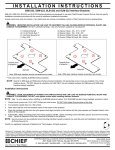
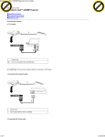
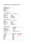
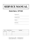
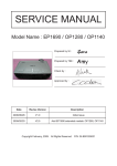
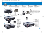
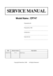
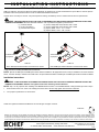
I N S T A L L AT I O N I N S T R U C T I O N S
SSB-315, SSM-315, SLB-315 and SLM-315 Interface Brackets
SSB-315, SSM-315, SLB-315 and SLM-315 Interface Brackets are designed for use with Chief® Series Projector Mounts. See the specific
installation instructions provided with the mount for additional installation information.
Unpack carton and verify kit contents. If any listed parts are missing, immediately contact a Chief Customer Service representative.
WARNING: IMPROPER INSTALLATION CAN LEAD TO EQUIPMENT FALLING CAUSING SERIOUS PERSONAL INJURY AND
DAMAGE TO EQUIPMENT! DO NOT substitute hardware. Use only hardware supplied by manufacturer!
(1) Interface Bracket
(3) Screw, Phillips Flat Head, Machine, M3 x 16mm
(4) 10-24 Thumb Nuts **
(3) Screw, Phillips Flat Head, Machine, M3 x 20mm
(1) All-Points Security Kit
(3) Spacer, Black, .375" x .171" x .4375"
(6) Spacer, White, .375" x .194" x .3125"
Towards front
of projector
Towards front
of projector
SLM-315
SLB-315
Note: SSB-style interface bracket connections are circled.
Note: SSM-style interface bracket connections are circled.
**Only used when installing SLB/SSB interface brackets.
NOTE: Specific to SSB-style and SSM-style interface bracket installation: All appropriate screws come pre-installed in the circled locations
above. DO NOT attempt to substitute and USE ONLY this pre-installed hardware for SSB-style and SSM-style interface bracket installation.
Installation Instructions
WARNING: OVER TIGHTENING OF SCREWS CAN DAMAGE PARTS AND CAN LEAD TO SERIOUS PERSONAL INJURY AND
DAMAGE TO EQUIPMENT! DO NOT over tighten screws when installing interface brackets.
NOTE: Step 1 is only required when installing an SLB/SSB interface bracket. If an SLM/SSM bracket is being installed, proceed to step 2.
1.
Screw thumb screws onto 10-24 x 5/8" Phillips pan head screws. DO NOT fully tighten thumb screws at this time.
2.
Turn projector upside down on a flat surface.
Chief® is a registered trademark of Milestone AV Technologies. All rights reserved.
continued....
Milestone AV Technologies, and its affiliated corporations and subsidiaries (collectively, "Milestone"), intend to make this manual accurate and complete. However, Milestone makes
no claim that the information contained herein covers all details, conditions or variations, nor does it provide for every possible contingency in connection with the installation or use
of this product. The information contained in this document is subject to change without notice or obligation of any kind. Milestone makes no representation of warranty, expressed or
implied, regarding the information contained herein. Milestone assumes no responsibility for accuracy, completeness or sufficiency of the information contained in this document.
Chief Manufacturing, a products division of Milestone AV Technologies
8850-000158 Rev03
©2010 Milestone AV Technologies,
8401 Eagle Creek Parkway, Savage, MN 55378
a Duchossois Group Company
• P: 800.582.6480 / 952.894.6280 • F:877.894.6918 / 952.894.6918
11/10
I N S T A L L AT I O N I N S T R U C T I O N S
Continued....
IMPORTANT ! : Some projector models may not be listed at this time. Follow instructions for the various install options after
you have determined which option matches your projector model.
WARNING: IF A BRACKET IS TOO LOOSE THE PROJECTOR COULD BE DAMAGED OR A FASTENER COULD BE TWISTED
OFF. If a bracket seems loose, move to try the next installation option.
3.
Verify if your projector model is listed for a recommended install option. If your projector model is NOT listed, start with Option 1 and
work through options one at a time.
Projector Models
Option 1
DELL® Models 2300MP, 5100MP
Option 2
DELL Models: 2100MP, 2200MP, 3200MP, 3300MP
HP® Models: sb21, xb31
Optoma® Models: H30,EP731,EP732,EP732B, EP732E,EP732H, EP737
Option 3
4.
DELL Model 4100MP
Place the correct spacers according to the option for your projector model.
•
•
•
OPTION 1: Center three .3125" white spacers over three threaded inserts in bottom of projector.
OPTION 2: Center three .4375" black spacers over three threaded inserts in bottom of projector.
OPTION 3: Use six .3125" white spacers, double-stacked, and place over three threaded inserts in bottom of projector.
5.
Place interface bracket on top of spacers aligning the mounting holes in the interface bracket with the holes in the spacers.
6.
Select the correct fasteners according to the option for your projector model.
•
•
•
7.
OPTION 1: Use three M3 x 16mm screws and secure interface bracket to projector by threading screws through bracket and spacers
and into threaded inserts in bottom of projector.
OPTION 2: Use three M3 x 16mm screws and secure interface bracket to projector by threading screws through bracket and spacers
and into threaded inserts in bottom of projector.
OPTION 3: Use three M3 x 20mm screws and secure interface bracket to projector by threading screws through bracket and spacers
and into threaded inserts in bottom of projector.
Tighten all fasteners at this time, securing the bracket to the projector.