1
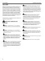
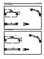
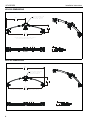
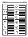
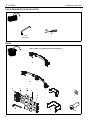
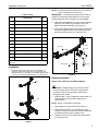
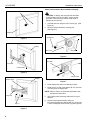
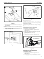
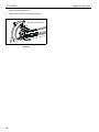
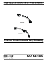
INSTALLATION INSTRUCTIONS
Istruzioni di installazione
Installatie-instructies
Instructions d´installation
Instrucciones de instalación
Installationsanleitung
Instruções de Instalação
KFA-220/225
KFA-320/325
Carts and Stands Horizontal Array Accessory
Spanish Product Description
German Product Description
Portuguese Product Description
Italian Product Description
Dutch Product Description
French Product Description
KFA SERIES
KFA SERIES
Installation Instructions
DISCLAIMER
Milestone AV Technologies and its affiliated corporations and
subsidiaries (collectively "Milestone"), intend to make this
manual accurate and complete. However, Milestone makes no
claim that the information contained herein covers all details,
conditions or variations, nor does it provide for every possible
contingency in connection with the installation or use of this
product. The information contained in this document is subject
to change without notice or obligation of any kind. Milestone
makes no representation of warranty, expressed or implied,
regarding the information contained herein. Milestone assumes
no responsibility for accuracy, completeness or sufficiency of
the information contained in this document.
Chief® and Centris™ a registered trademarks of Milestone AV
Technologies. All rights reserved.
IMPORTANT WARNINGS AND
CAUTIONS!
WARNING: Exceeding the weight capacity can result in
serious personal injury or damage to equipment! It is the
installer’s responsibility to make sure the combined weight of
the displays installed does not exceed 70 lbs (31.8 kg) for the
KFA-220 and KFA-225 and 90 lbs (40.8 kg) for the KFA-320
and KFA-325. The weight of each individual display must not
exceed 35 lbs (15.9 kg) for the KFA-220 and KFA-225 or 30
lbs for the KFA-320 and KFA-325.
WARNING: RISK OF ELECTRIC SHOCK ! Using the
wrong screws could result in severe personal injury or
damage to your display. If your display uses a longer screw
size than those included in the kit, DO NOT use the screws
provided with the kit. Use the screws provided with your
display or contact the manufacturer.
WARNING: Improper installation can result in serious
personal injury! Make sure that the mounting surface can
support a redundant weight factor five times the total weight
of the equipment. If not, reinforce the mounting surface
structural members before installing the mount.
WARNING: A WARNING alerts you to the possibility of
serious injury or death if you do not follow the instructions.
WARNING: Be aware of the potential for personal injury or
damage to the unit if it is not adequately mounted.
CAUTION: A CAUTION alerts you to the possibility of
damage or destruction of equipment if you do not follow the
corresponding instructions.
WARNING: The installer is responsible for verifying that
the mounting surface to which the KFA is anchored will safely
support the combined load of all attached components or
other equipment.
WARNING: Failure to read, thoroughly understand, and
follow all instructions can result in serious personal injury,
damage to equipment, or voiding of factory warranty! It is the
installer’s responsibility to make sure all components are
properly assembled and installed using the instructions
provided.
WARNING: Failure to provide adequate structural strength
for this component can result in serious personal injury or
damage to equipment! It is the installer’s responsibility to
make sure the structure to which this component is attached
can support five times the combined weight of all equipment.
Reinforce the structure as required before installing the
component.
2
WARNING: Watch for pinch points. Do not put your fingers
between movable parts.
WARNING: Make sure the mount is correctly oriented.
Installation Instructions
KFA SERIES
KFA-220 DIMENSIONS
CLAMP FOR ATTACHING
TO PF AND MF SERIES
CARTS AND STANDS
13.68
5.68
23.83
IF SAME SIZE DISPLAY IS USED FOR BOTH,
MAXIMUM SCREEN WIDTH OF 22.7".
1.96
4.50
KFA-225 DIMENSIONS
CLAMP FOR ATTACHING
TO PF AND MF SERIES
CARTS AND STANDS
17.24
437.8
6.68
30.51
774.8
IF SAME SIZE DISPLAY IS USED FOR BOTH,
MAXIMUM SCREEN WIDTH OF 30.0".
1.96
49.8
4.50
114.3
3
KFA SERIES
Installation Instructions
KFA-320 DIMENSIONS
CLAMP FOR ATTACHING
TO PF AND MF SERIES
CARTS AND STANDS
20.80
528.3
7.93
201.5
37.14
943.3
IF SAME SIZE DISPLAY IS USED FOR ALL THREE,
MAXIMUM SCREEN WIDTH OF 18.0".
1.96
49.8
4.50
114.3
KFA-325 DIMENSIONS
53.81
1366.7
CLAMP FOR ATTACHING
TO PF AND MF SERIES
CARTS AND STANDS
10.87
276.1
48.69
1236.7
IF SAME SIZE DISPLAY IS USED FOR ALL THREE,
MAXIMUM HORIZONTAL SCREEN WIDTH OF 25.00" [635.0].
1.96
49.8
4
4.50
114.3
Installation Instructions
KFA SERIES
LEGEND
Tighten Fastener
Pencil Mark
Apretar elemento de fijación
Marcar con lápiz
Befestigungsteil festziehen
Stiftmarkierung
Apertar fixador
Marcar com lápis
Serrare il fissaggio
Segno a matita
Bevestiging vastdraaien
Potloodmerkteken
Serrez les fixations
Marquage au crayon
Loosen Fastener
Drill Hole
Aflojar elemento de fijación
Perforar
Befestigungsteil lösen
Bohrloch
Desapertar fixador
Fazer furo
Allentare il fissaggio
Praticare un foro
Bevestiging losdraaien
Gat boren
Desserrez les fixations
Percez un trou
Phillips Screwdriver
Adjust
Destornillador Phillips
Ajustar
Kreuzschlitzschraubendreher
Einstellen
Chave de fendas Phillips
Ajustar
Cacciavite a stella
Regolare
Kruiskopschroevendraaier
Afstellen
Tournevis à pointe cruciforme
Ajuster
Open-Ended Wrench
Remove
Llave de boca
Quitar
Gabelschlüssel
Entfernen
Chave de bocas
Remover
Chiave a punte aperte
Rimuovere
Steeksleutel
Verwijderen
Clé à fourche
Retirez
By Hand
Optional
A mano
Opcional
Von Hand
Optional
Com a mão
Opcional
A mano
Opzionale
Met de hand
Optie
À la main
En option
Hex-Head Wrench
Security Wrench
Llave de cabeza hexagonal
Llave de seguridad
Sechskantschlüssel
Sicherheitsschlüssel
Chave de cabeça sextavada
Chave de segurança
Chiave esagonale
Chiave di sicurezza
Zeskantsleutel
Veiligheidssleutel
Clé à tête hexagonale
Clé de sécurité
5
KFA SERIES
Installation Instructions
TOOLS REQUIRED FOR INSTALLATION
#2
5/32"
(included)
PARTS
(refer to Table 1 for quantities and part descriptions)
A
B
D
C
E
F
G
H
6
J
K
L
M
Installation Instructions
KFA SERIES
NOTE: If removing existing head assembly from cart/stand, do
so prior to installing KFA Series arrays.
Table 1: Parts
ITEM
DESCRIPTION
QTY*
A
ARRAY ASSEMBLY, KFA-220/225
1
B
ARRAY ASSEMBLY, KFA-320/325
1
C
SCREW, Phillips Pan Head, M4 x 12mm
4
D
SCREW, Phillips Pan Head, M4 x 30mm
4
E
SPACER, Nylon, 3/4" (used with item D)
4
F
SPACER, Nylon, 3/8" (used with item G)
4
G
SCREW, Phillips Pan Head, M4 x 20mm
4
H
KEY, Hex, 5/32"
1
J
BRACKET, Pole Clamp, Back - small
1
K
BRACKET, Pole Clamp, Back - large
1
L
WASHER, Flat. 1/4"
2
M
SCREW, Button Head, 1/4-20 x 3/4"
2
IMPORTANT ! : The KFA Series arrays can be used in
addition to the existing head assembly as long as the
overall weight limit of the cart/stand is not exceeded!
2. Attach pole clamp bracket (J or K) to pole mount front
using two 1/4" washers (L) and two 1/4-20 x 3/4"
button head cap screws (M). (See Figure 2)
3. Secure pole clamp bracket (J or K) to pole mount front
and pole by tightening two button head cap screws
(M) using a 5/32" hex key (H). (See Figure 2)
(J or K)
(A or B)
(L) x 2
* Quantity varies depending upon the number of displays being
mounted.
pole mount
(M) x 2
Installation
1.
Determine proper pole clamp to use for installation. If
mounting to wide portion of pole mount use large pole
clamp bracket (K). If mounting to extendable upper portion
of mount, use small pole clamp bracket (J). (See Figure 1)
Figure 2
Display Installation
(J)
Attach Centris Head to Flush Mount Display
CAUTION: If display uses a screw size other than
those included in the kit, DO NOT use the screws
provided. Using the wrong screws could result in
damage to your monitor.
(K)
1. Install two M4 x 12mm Phillips pan head screws (C)
into two upper mounting holes in display back.
(See Figure 3)
NOTE: DO NOT fully tighten at this time.
2. Hang display on Centris head. (See Figure 4)
3. Install bottom two M4 x 12mm Phillips pan head
screws (C) through Centris head mounting holes and
into lower mounting holes in display back.
4. Tighten four M4 x 12mm Phillips pan head screws
(C). (See Figure 5)
Figure 1
7
KFA SERIES
Installation Instructions
Attach Centris Head to Recessed Mount Display
(C) x 2
CAUTION: If display uses a screw size other than
those included in the kit, DO NOT use the screws
provided. Using the wrong screws could result in
damage to your monitor.
1. Uninstall end lock using the 5/32" hex key (H). (See
Figure 6)
1
2. Remove Centris head from mounting rail.
(See Figure 7)
Display
Centris Head
Square Nut
Figure 3
1
Display
Array Rail
End Lock
2
Figure 6
Array Rail
Array Rail
Centris Head
2
Figure 4
Centris Head
Display
Centris Head
Figure 7
3. Place display face down on a clean dry surface.
4. Place four 3/4" or 3/8" nylon spacers (E or F) over four
mounting holes in display back.
NOTE: Refer to Table 1 to select the applicable screw
and spacer combination.
3
Array Rail
6. Secure Centris head to display using four
M4 x 20mm Phillips pan head screws (G), or four M4
x 30mm Phillips pan head screws (D).(See Figure 8)
(C) x 2
Figure 5
8
5. Align Centris head mounting holes with four nylon
spacers.
Installation Instructions
KFA SERIES
Array Rail
6 (G or D) x 4
End Lock
Centris Head
5
4 (E or F) x 4
Centris Head
End Lock Retaining Screw
Figure 10
Display
Figure 8
7. Slide display with Centris bracket onto mounting rail.
(See Figure 9)
NOTE: Repeat previous steps for each additional display.
8. Install end locks into mounting rail using the 5/32" hex
key (H). (See Figure 10)
Display Adjustment
These pivot arrays allow horizontal, pitch, roll, and yaw
adjustment of each display with a maximum pitch range
of 15° up and 15° down.
These pivot arrays also allow a full 360 deg. of display
roll.
Display Horizontal Position Adjustment
To adjust display horizontal position:
1. Loosen Centris bracket rear adjustment knob.
(See Figure 11)
Display with Centris Bracket
2. Slide Centris bracket with display left or right until
properly positioned on array rail.
3. Tighten Centris bracket rear adjustment knob.
7
rear adjustment knob
Array Rail
Figure 9
Figure 11
Display Pitch, Roll, and Yaw Adjustment
To adjust display position:
1. Loosen Centris bracket front adjustment knob.
(See Figure 12)
2. Tilt display up or down, or adjust display roll left or
9
KFA SERIES
Installation Instructions
right until properly positioned.
3. Tighten Centris bracket front adjustment knob.
pitch/roll adjustment knob
Figure 12
10
Installation Instructions
KFA SERIES
11
KFA SERIES
Installation Instructions
USA/International
Europe
Chief Manufacturing, a products division
of Milestone AV Technologies
8834-000011 REV 01
2010 Milestone AV Technologies, a
Duchossois Group Company
www.chiefmfg.com
04/10
Asia Pacific
A
P
F
A
P
F
A
8401 Eagle Creek Parkway, Savage, MN 55378
800.582.6480 / 952.894.6280
877.894.6918 / 952.894.6918
Fellenoord 130 5611 ZB EINDHOVEN, The Netherlands
+31 (0)40 2668620
+31 (0)40 2668615
Office No. 1 on 12/F, Shatin Galleria
18-24 Shan Mei Street
Fotan, Shatin, Hong Kong
P 852 2145 4099
F 852 2145 4477