1
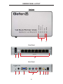
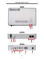
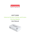
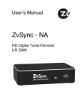
1:8 Multi Format Video Distribution
over Ethernet
GTV-MFDA-148
User Manual
ASKING FOR ASSISTANCE
Technical Support:
Telephone
Fax
(818) 772-9100
(800) 545-6900
(818) 772-9120
Technical Support Hours:
8:00 AM to 5:00 PM Monday thru Friday.
Write To:
Gefen, LLC
c/o Customer Service
20600 Nordhoff St
Chatsworth, CA 91311
www.gefentv.com
[email protected]
Notice
Gefen, LLC reserves the right to make changes in the hardware, packaging, and
any accompanying documentation without prior written notice.
1:8 Multi Format Video Distribution over Ethernet
is a trademark of Gefen, LLC
© 2011 Gefen, LLC. All rights reserved.
All trademarks are the property of their respective companies.
Rev A2
CONTENTS
1
Introduction
2
Operation Notes
3
Features
4
Sender Panel Layout
5
Sender Panel Descriptions
6
Receiver Panel Layout
7
Receiver Panel Descriptions
8
Connecting and Operating The Unit
8
Distribution of Video and Audio over CAT-5
9
Distribution of Video and Audio over LAN
10
Operation As a Switch
11
Wiring Diagrams
12
IR Backchannel Configuration
13
Video Input and Output Format Conversion Table
14
Specifications
15
Warranty
INTRODUCTION
Congratulations on your purchase of the 1:8 Multi Format Video Distribution over
Ethernet. Your complete satisfaction is very important to us.
GefenTV
GefenTV is a unique product line catering to the growing needs for innovative
home theater solutions. We specialize in total integration for your home theater,
while also focusing on going above and beyond customer expectations to ensure
you get the most from your hardware. We invite you to explore our distinct
product line and hope you find your solutions. Don’t see what you are looking for
here? Please call us so we can better assist you with your particular needs.
The GefenTV 1:8 Multi Format Video Distribution over Ethernet
This versatile product is useful for PCs, digital signage applications, and
educational institutions. VGA, Component, S-Video, or Composite video data
is broadcast from the Sender up to 330 ft over CAT-5 to the Receiver. The
Receiver provides VGA or Component output and can be daisy-chained.
Additional features of this product allow video and audio distribution over a Local
Area Network (LAN).
How It Works
The GefenTV 1:8 Multi Format Video Distribution over Ethernet is a Sender/Receiver system allowing broadcast of analog video and audio over Ethernet cable
to a maximum of eight (8) Receivers. Distribution of video and audio over LAN
can also be achieved by connecting a single Ethernet cable from the Sender unit
to a LAN connection. See page 9 for details.
1
OPERATION NOTES
READ THESE NOTES BEFORE INSTALLING OR OPERATING
THE 1:8 MULTI FORMAT VIDEO DISTRIBUTION OVER ETHERNET
•
This product is Ethernet-based, not IP-based.
•
It is recommended that a managed switch with multicast support be
placed between the Sender Unit and Receiver Unit(s). The multicast
function should be enabled on the switch.
•
If a non-managed switch is used, VGA Sender multicast packets will be
broadcast to all outputs of the switch. This unit uses about 80 Mbs to
send audio and video.
•
Once the Receiver Unit is connected to the same LAN, it will
automatically link to the Sender Unit.
•
Receivers Unit(s) cannot be placed outside of a LAN.
•
Conforms to IEEE 802.3 standards.
2
FEATURES
Features
•
Extend video and audio up to 330 ft (100 m) using CAT-5.
•
Maximum Input Resolutions: 1080p@60Hz (Component), 1280x1024@60Hz
(VGA), 480i@60Hz, 576i@50Hz (S-Video, Composite)
•
Maximum Output Resolutions: 720p@60Hz (Component),
1280x1024@60Hz (VGA), 480i@60Hz, 576i@50Hz (S-Video, Composite)
•
Switch between four audio/video sources from the Sender location
•
Plug-and-Play installation (with no special hardware or software
configuration required)
•
2-Channel Stereo Analog Audio supported
•
PCM Encoding is 48KHz 16-bit sampling
Package Includes
(1) GefenTV 1:8 Multi Format Video Distribution over Ethernet Sender Unit
(1) GefenTV 1:8 Multi Format Video Distribution over Ethernet Receiver Unit
(1) 6 ft VGA Cable (M-M)
(1) 12V DC Power Supplies
(1) User Manual
3
SENDER PANEL LAYOUT
Top Panel
1
2
Front Panel
3
5
4
Back Panel
6
7
9
8
4
10
11 12 13
SENDER PANEL DESCRIPTIONS
1
Input Selection Indicators
Indicates the current input selection: Composite, S-Video, Component,
or VGA
2
Power Indicator
This LED will glow blue when the power is on.
3
Power On/Off Switch
Turn the power on or off using this button
4
Selector Button
Switches between Component Video, S-Video, Composite and VGA
5
Ethernet (RJ-45) Input Connectors
Use this jack point to connect another receiver into the system
6
Reset Button
Reset the sender unit
7
Analog Stereo Audio Input
Use this input to connect a 3.5mm analog stereo audio line-in jack
8
VGA Video Input
Use this input to connect a VGA video input from a computer source
9
Component Video Inputs
Use this input to connect an Analog RCA Component
10 S-Video Input
Use this input to connect S-Video sources
11 Composite Video Input
Use this input to connect Composite video
12 IR Back-Channel Port
Use this port to connect an IR blaster cable (Gefen Part No. EXT-2IREMIT,
not included)
13 12V DC Power Receptacle
Used to connect the included 12V DC power supply
5
RECEIVER PANEL LAYOUT
Top Panel
1
2
Front Panel
3
4
5
6
Back Panel
7
8
10
9
6
11
RECEIVER PANEL DESCRIPTIONS
1
Output Selection Indicator
Indicates the current output selection: Component or VGA
2
Power Indicator
This LED will glow blue when the Receiver is powered on
3
Power On/Off Switch
Turn the power on or off using this button
4
Selector Button
Switches between Component or VGA output
5
IR Sensor
Infrared lens senses signals from remote control
6
Ethernet (RJ-45) Output Connectors
Use this input to connect Ethernet cables
7
Reset Button
Resets the receiver unit
8
Analog Stereo Audio Output
Connect a stereo RCA cable to these outputs.
9
Component Video Output
Use this input to connect component video
10 VGA Output Connector
Use this to connect analog VGA displays
11 12V DC Power Receptacle
Used to connect the included 12V DC power supply
7
CONNECTING AND OPERATING THE 1:8 MULTI FORMAT
VIDEO DISTRIBUTION OVER ETHERNET
How to Connect the
GefenTV 1:8 Multi Format Video Distribution over Ethernet
(Direct Connection using Sender and Receiver)
1.
Connect the source(s) to the Sender unit using VGA, Component, Composite or S-Video cables. If audio is desired on the output, connect a 3.5mm
mini stereo audio cable to the rear of the Sender unit. Connect the other
end of the audio cable to the audio source.
2.
Connect the Receiver to the display using a VGA and/or a Component cable.
3.
Attach one end of an Ethernet cable from the Sender unit to each Receiver.
The Ethernet cable(s) connecting the Sender to the Receiver should be no
longer than 100 meters (330 feet) in length.
4.
Using one of the included 12V DC power supplies, connect it to the power
receptacle at the rear of the Sender unit. Connect the power adapter to an
available wall outlet.
5.
Connect the other 12V DC power supply to the Recevier unit then plug the
adapter into an available wall outlet.
6.
Use the SELECT button on the Sender unit (page 4) to select the desired
input video source. Pressing the SELECT button on the Sender will cycle
through each input on the Sender. The LED next to the selected output will
be displayed on the Input Selection Indicator (page 4).
7.
Use the SELECT button on the Receiver unit (page 6) to select between
VGA or Component output. The LED next to the selected output will be
displayed on the Output Selection Indicator (page 6).
8.
Once the correct video input and output selections are made, video will appear on the connected display. If audio is used on the Sender and Receiver,
audio should be heard clearly through the display.
Note: The maximum supported input and output resolution for VGA is
1280x1024 @ 60Hz. YPbPr (Component) output supports a maximum of 720p
@ 60Hz.
8
CONNECTING AND OPERATING THE 1:8 MULTI FORMAT
VIDEO DISTRIBUTION OVER ETHERNET
Configuring the GefenTV 1:8 Multi Format Distribution Over Ethernet
for Video / Audio over LAN
In addition to extending video and audio over Ethernet, the GefenTV 1:8 Multi
Format Distribution Over Ethernet can be used to distribute Video and Audio over
a Local Area Network (LAN).
1.
Connect the source(s) to the Sender unit using VGA, Component, Composite or S-Video cables. If audio is desired on the output, connect a 3.5mm
mini stereo audio cable to the rear of the Sender unit (page 4). Connect the
other end of the audio cable to the audio source.
2.
Connect an Ethernet cable from the Local Area Network to one of the Ethernet jacks on the front of the Sender.
3.
Connect the Receiver to a display using VGA and/or Component cables.
4.
Connect an Ethernet cable from the Local Area Network to one of the Ethernet jacks on the front of the Receiver.
5.
Using one of the included 12V DC power supplies, connect it to the power
receptacle at the rear of the Sender unit. Connect the power adapter to an
available wall outlet.
6.
Connect the other 12V DC power supply to the Recevier unit then plug the
adapter into an available wall outlet.
7.
Use the SELECT button on the Sender unit (page 4) to select the desired
input video source. Pressing the SELECT button on the Sender will cycle
through each input on the Sender. The LED next to the selected output will
be displayed on the Input Selection Indicator (page 4).
8.
Use the SELECT button on the Receiver unit (page 6) to select between
VGA or Component output. The LED next to the selected output will be
displayed on the Output Selection Indicator (page 6).
9.
Once the correct video input and output selections are made, video should
appear on the connected display. If audio is used on the Sender and Receiver, audio should be heard clearly through the display speakers.
9
CONNECTING AND OPERATING THE 1:8 MULTI FORMAT
VIDEO DISTRIBUTION OVER ETHERNET
Connecting additional computers using the
GefenTV 1:8 Multi Format Video Distribution over Ethernet
In addition to distribution video and audio over LAN, computers can also be
connected within the network.
1.
Follow the steps on page 9 for Configuring the GefenTV 1:8 Multi Format
Distribution Over Ethernet for Video / Audio over LAN.
2.
Using an Ethernet cable, connect each computer to either the Sender or
Receiver unit. The Sender functions as a switch and it is possible to connect
multiple computers or Receiver units.
3.
The computers connected to the Sender or Receiver should now be able to
access the LAN without any additional configuration. It should be noted that
connecting computers to the Sender will minimize the number or Receivers
that can be used with the Sender.
NOTE: The GefenTV 1:8 Multi Format Video Distribution over Ethernet can operate independently of an Ethernet switch. However, when configuring for video
/ audio and computers over LAN, it is suggested that an IGMP switch be used to
manage the video / audio data and computer data. This will ensure the correct
data is sent to the proper port and maintain optimal bandwidth.
10
CONNECTING AND OPERATING THE 1:8 MULTI FORMAT
VIDEO DISTRIBUTION OVER ETHERNET
Wiring Diagram for connecting directly using CAT-5:
Wiring Diagram for connecting over LAN using CAT-5:
11
IR BACKCHANNEL CONFIGURATION
Controlling devices using the IR Backchannel
On the rear of the Sender unit is the IR backchannel port (see page 4, item
12). IR commands that are received through the IR receiver (see page 6, item
5) will be transmitted back to the source for output through the attached IR
backchannel. The IR backchannel uses an infrared emitter referred to as an “IR
Blaster” (Gefen Part No. EXT-2IREMIT, not included).
1.
Connect the 3.5mm jack of the IR Blaster cable to the rear of the Sender unit
(see page 4).
2.
Place the IR emitter over the IR sensor of the source.
To control the source, direct the source remote at the Receiver unit as shown
in Fig. 1.1. The IR commands from the source remote are transmitted over
the CAT-5 and relayed to the source. In a LAN application, devices in different
rooms (or floors) can be controlled as long as the Sender and Receiver are
connected to the same network. The IR Backchannel can greatly increase the
flexibilty when controlling the source, particularly at great distances.
Fig. 1.1: Controlling the source remotely, using an IR Blaster
12
VIDEO CONVERSION TABLE
The following table lists the input and output formats for the GefenTV 1:8 Multi
Format Video Distribution over Ethernet. Note that some output timings may
differ from input timings. This is a limitation of the hardware. For example, a
Component input of 1080p 60Hz (at the Sender) is limited to 720p 60Hz on the
output (at the Receiver).
Input and Output Formats
Input Frequency
Output Frequency
VGA
VGA
Component
S-Video
Composite
YPbPr
640x480 60Hz
640x480 60Hz
480p 60Hz
800x600 60Hz
800x600 60Hz
480p 60Hz
1024x768 60Hz
1024x768 60Hz 720p 60Hz
1280x768 60Hz
1280x768 60Hz 720p 60Hz
1280x1024 60Hz
1280x1024
720p 60Hz
480i 60Hz
640x480 60Hz
480p 60Hz
480p 60Hz
640x480 60Hz
480p 60Hz
576i 50Hz
800x600 75Hz
576p 50 Hz
576p 50Hz
800x600 75 Hz
576p 50Hz
720p 60Hz
1280x720 60Hz 720p 60Hz
720p 50Hz
1280x720 60Hz 720p 60Hz
1080i 60Hz
1280x720 60Hz 720p 60Hz
1080i 50Hz
1280x720 60Hz 720p 60Hz
1080p 60Hz
1280x720 60Hz 720p 60Hz
1080p 50Hz
1280x720 60Hz 720p 60Hz
480i 60Hz
640x480 60Hz
480p 60Hz
576i 50Hz
800x600 75Hz
576p 50Hz
480i 60Hz
640x480 60Hz
480p 60Hz
576i 50Hz
800x600 75Hz
576p 50Hz
13
SPECIFICATIONS
PCM Encoding....................................................2-channel 48KHz 16-bit sampling
Power Supply............................................................................2 x 12V @ 1A each
Audio Inputs/Outputs.........................................................3.5mm mini-stereo jacks
Video Inputs:
VGA.................................................................................1280X1024@60Hz (max)
Component..................................................................................1080p60Hz (max)
Composite & S-Video.............................................480i@60Hz, 576i@50Hz (max)
Video Outputs:
VGA.................................................................................1280X1024@60Hz (max)
Component................................................................................720p@60Hz (max)
Communication Protocol........................................................................Full Duplex
Ethernet Standard..................................................................................IEEE 802.3
Network Bandwidth.....................................................................40Mb/s ~ 100Mb/s
Operating Temperature...................................................................0-40 degrees C
Operating Humidity..............................................90% maximum (non-condensing)
Dimensions.........................................4.5”W x 1.3”H x 7.25”D (Sender / Receiver)
14
WARRANTY
Gefen warrants the equipment it manufactures to be free from defects in material
and workmanship.
If equipment fails because of such defects and Gefen is notified within two (2)
years from the date of shipment, Gefen will, at its option, repair or replace the
equipment, provided that the equipment has not been subjected to mechanical,
electrical, or other abuse or modifications. Equipment that fails under conditions
other than those covered will be repaired at the current price of parts and labor in
effect at the time of repair. Such repairs are warranted for ninety (90) days from
the day of reshipment to the Buyer.
This warranty is in lieu of all other warranties expressed or implied, including
without limitation, any implied warranty or merchantability or fitness for any
particular purpose, all of which are expressly disclaimed.
1.
Proof of sale may be required in order to claim warranty.
2.
Customers outside the US are responsible for shipping charges to and from
Gefen.
3.
Copper cables are limited to a 30 day warranty and cables must be in their
original condition.
The information in this manual has been carefully checked and is believed to
be accurate. However, Gefen assumes no responsibility for any inaccuracies
that may be contained in this manual. In no event will Gefen be liable for
direct, indirect, special, incidental, or consequential damages resulting from
any defect or omission in this manual, even if advised of the possibility of such
damages. The technical information contained herein regarding the features and
specifications is subject to change without notice.
For the latest warranty coverage information, refer to the Warranty and Return
Policy under the Support section of the Gefen Web site at www.gefen.com.
PRODUCT REGISTRATION
Please register your product online by visiting the Register Product page
under the Support section of the Gefen Web site.
15
Rev A2
20600 Nordhoff St., Chatsworth CA 91311
1-800-545-6900
818-772-9100
www.gefen.com
Pb
This product uses UL listed power supplies.
fax: 818-772-9120
[email protected]