1
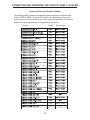
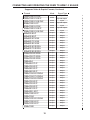
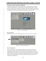
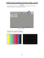
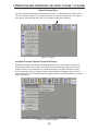
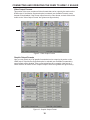
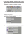
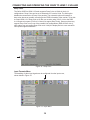
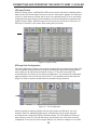
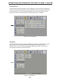
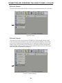
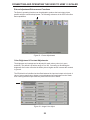
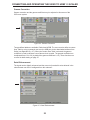
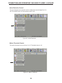
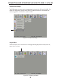
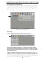
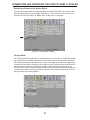
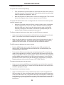
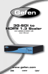
®
3GSDI to
HDMI® 1.3 Scaler
EXT-3GSDI-2-HDMI1.3S
User Manual
www.gefen.com
ASKING FOR ASSISTANCE
Technical Support:
Telephone
Fax
(818) 772-9100
(800) 545-6900
(818) 772-9120
Technical Support Hours:
8:00 AM to 5:00 PM Monday thru Friday, Pacific Time
Write To:
Gefen, LLC.
c/o Customer Service
20600 Nordhoff St
Chatsworth, CA 91311
www.gefen.com
[email protected]
Notice
Gefen, LLC reserves the right to make changes in the hardware, packaging, and
any accompanying documentation without prior written notice.
3GSDI to HDMI 1.3 Scaler is a trademark of Gefen, LLC
HDMI, the
logo, and High-Definition Multimedia Interface are
trademarks or registered trademarks of HDMI Licensing in the United States and
other countries.
© 2011 Gefen, LLC. All rights reserved.
All trademarks are the property of their respective owners.
Rev B5
CONTENTS
1
2
3
4
5
6
28-29
30
31
32
33
Introduction
Operation Notes
Features
Panel Layout
Panel Descriptions
Connecting And Operating The 3G-SDI To HDMI Scaler
6
Setting up the Scaler for the First Time
7
RMT-8HDS-IR Remote Description
8
IR Remote Installation
9
RMT-8HDS-IR Remote Configuration
10
Controlling the 3GSDI to HDMI 1.3 Scaler
11
Supported Video & Graphics Formats
13
Utilizing the On-Screen Display (OSD) Menu
General Operations
Save Configuration
14
Patterns
Color Bars & Cross-Hatch Patterns
15
Output Formats Menu
15
Available Formats /
Monitor Supported Feature
16
Video Output Formats
Graphic Output Formats
17
Custom Output Formats
HDMI Output Link Configuration
Frame Rate
18
Deep Color
18
Input Formats Menu
19
SDI Input Format
SDI Input Link Configuration
20
Clean Aperature
Film Mode
21
SDI Audio Channel Selection
IR Remote Channel
22
Picture Adjustments/Enhancement Functions
22
Color Brightness & Contrast Adjustments
23
Gamma Correction
Detail Enhancement
24
Noise Reduction
Motion Threshold
25
Output Color Range
25
Layout Menu
26
Size and Position of the Output Picture
Aspect Ratio
27
Extracting a Subset of the Source Signal
Through Mode
Troubleshooting
Appendix A: Gamma User Table Update
Appendix B: Software Updates
Specifications
Warranty
INTRODUCTION
Congratulations on your purchase of the 3GSDI to HDMI 1.3 Scaler. Your
complete satisfaction is very important to us.
Gefen
Gefen delivers innovative, progressive computer and electronics add-on solutions
that harness integration, extension, distribution and conversion technologies.
Gefen’s reliable, plug-and-play products supplement cross-platform computer
systems, professional audio/video environments and HDTV systems of all sizes
with hard-working solutions that are easy to implement and simple to operate.
The Gefen 3GSDI to HDMI 1.3 Scaler
The Gefen 3GSDI to HDMI 1.3 Scaler will take any SDI, HD-SDI, or 3G-SDI
video signal and convert it to HDMI 1.3 scaled to the output resolution of your
display device. The SDI input signal will simply be converted to an HDMI signal.
A user-friendly On-Screen Display will allow the user to select features such as
Deep Color conversion and colorspace. A built-in 720p (60Hz) test pattern is also
available without connecting an SDI source, useful for checking the HDMI video
output. An SDI loop out and a S/PDIF digital audio output are also provided for
monitoring the input SDI source and/or distributing the SDI audio to an external
digital amplification device.
How It Works
The 3GSDI to HDMI Scaler converts an SDI source signal (SD/HD/3G-SDI) to
an HDMI 1.3-compliant A/V signal which is then scaled to optimally fit the output/
display device at resolutions of up to 2048x1080p24.
The SDI source device is connected to the SDI input. An HDMI-compliant output
device is connected to the HDMI A/V output connector. The included power
supply is connected and plugged into an available wall socket. The input signals
are now converted to the proper output format and scaled to your choice of
resolutions on the output device.
1
OPERATION NOTES
READ THESE NOTES BEFORE INSTALLING OR
OPERATING THE 3GSDI TO HDMI 1.3 SCALER
•
The built-in GUI (Graphical User Interface) or On-Screen Display (OSD)
provides convenient operation of the Scaler. The supplied IR Remote
control operates the OSD. Page 10 and following cover OSD functions.
•
The IR Remote’s operating channel must be identical to that of the Scaler.
Please see page 9 for complete details on how to configure the IR Channel.
•
The 3GSDI to HDMI 1.3 Scaler supports many input and output resolutions.
For a complete list of supported formats, see the tables on pages 10 and 11.
•
Supports SMPTE standards 259M, 292M, SMPTE 274M, SMPTE 296M,
ITU-R BT.656 and ITU-R BT.601. Handles 3G-SDI hvv 425-A and 425-B /
formats 1080P 50/59.94/60.
•
Supports HDMI 1.3 with 225 MHz Video Bandwidth, 10-bit Deep Color
(RGB & YCbCr 4:4:4 only), and up to 8 channels of converted SDI audio
embedded into HDMI.
•
Internal software (firmware) may be upgraded via the built-in Serial or USB
ports. A DB9 serial cable is provided for this purpose. Note that software
updates performed on the USB port will be quicker due to its higher data
transfer rate.
2
FEATURES
Features
•
View 3G-SDI video directly from a 3G-SDI network scaled onto any HDMIcompliant display at any resolution you choose.
•
225 MHz Video Bandwidth (max. output resolution supported:
2048x1080/24)
•
10-bit Deep Color (RGB & YCbCr 4:4:4 only)
•
Up to 8 channels of PCM audio embedded into the HDMI output signal
•
Dolby Digital/DTS AC3 encoded audio
•
Separate multi-channel S/PDIF digital audio output of converted SDI audio
for amplification and/or monitoring purposes.
•
User-Friendly On-Screen Display (OSD) menu system combined with an
IR Remote Control enables intuitive adjustment of a wide variety of image
processing functions.
•
Local 3G-SDI output for each 3G-SDI source permits connection to
additional 3G-SDI products on a SDI network and viewing of input sources
on 3G-SDI based monitors
•
The built-in Genlock Reference Input connector enables synchronization of
the Scaler to other television picture sources on an SDI network (both trilevel and blackburst)
•
Automatic detection of SD-, HD- and 3G-SDI formats on the inputs
•
Field upgradable firmware using the built-in USB 2.0 port or RS-232 Serial
port.
•
Many other powerful features including pattern generation, aspect ratios,
detail enhancement, noise reduction, Film Mode, and much more.
Package Includes:
(1) Gefen 3GSDI to HDMI 1.3 Scaler
(1) IR Remote Control Unit
(1) DB9 Serial Cable (M-F)
(1) 5V DC Locking Power Supply
(1) Set of Rack Ears
(1) User Manual
3
PANEL LAYOUT
Front
1
2
3
4
Back
5
6
7
8
9
4
10
11
12
PANEL DESCRIPTIONS
1
IR Window (Sensor)
Electronic sensor which receives IR commands from the IR Remote Control.
2
Power LED Indicator (Red)
Becomes active when power is supplied to the Scaler via the included 5V power
adapter. Also indicates when there is an error with the Scaler. If the Scaler
encounters an error that it cannot fix, it will blink the power LED (please see the
Troubleshooting section for further information on page 25).
3
3G LED Indicator (Blue)
Lights up when input to the Scaler is a 3G-SDI signal.
4
RS-232 Serial Port
This port is used to control the Scaler using RS-232. A DB9 serial cable is
provided for this purpose.
5
5V Locking Power Input Connector
Plug the included power supply’s threaded power connector into this terminal
and screw it in firmly, then plug in the wall adapter.
6
USB 2.0 Input Port
This high-speed input port is used to update the internal software of the Scaler
(see page 27). The user must supply a USB cable to utilize this port.
7
S/PDIF Coaxial Digital Audio Ouput
Outputs up to 5.1 channels of digital audio extracted from the HDMI source to a
S/PDIF coaxial digital output for monitoring and/or external amplification.
8
SD/HD/3G-SDI Input 1
Receives incoming SDI source signal No. 1.
9
SD/HD/3G-SDI Loop Output 1
Allows monitoring of SDI source signal No. 1 (no scaling is performed).
10 SD/HD/3G-SDI Input 2
Receives incoming SDI source signal No. 2 (no input selection is allowed).
11 SD/HD/3G-SDI Loop Output 2
Allows monitoring of SDI source signal No. 2 before conversion to HDMI takes
place (no scaling is performed).
12 HDMI Output
Sends converted SD/HD/3G-SDI to an HDMI display/output device.
5
CONNECTING AND OPERATING THE 3GSDI TO HDMI 1.3 SCALER
Setting up the Scaler for the First Time
1.
Connect the SD/HD/3G-SDI source(s) to the SDI input(s) on the Scaler. If using a
dual-link SDI source, ensure that both SDI inputs 1 and 2 are connected. If SDI source
monitoring is desired, connect an SDI output device on the SDI loop output.
2.
SDI audio may be monitored on digital audio equipment by connecting amplification/
output devices to the S/PDIF output on the Scaler.
3.
Connect an HDMI-compliant output device to the HDMI output port on the 3GSDI
to HDMI 1.3 Scaler. Connect the included 5V DC power supply’s locking power
connector to the Scaler, then connect the AC adaptor to an available wall socket.
4.
Operation of the Scaler is done by the included IR Remote Control. The remote
control has directional buttons to navigate within the On-Screen Display (OSD) menu
system that drives the Scaler. The MENU button brings up the OSD and the OK button
confirms a choice or selection.
Be sure you have read the contents of page 7, “EXT-RMT-8HDS-IR Remote
Description” to familiarize yourself with the IR remote control supplied with the Scaler.
5.
Power up the Scaler. The Power LED indicator will turn red. Press the MENU button
on the included IR Remote to activate the OSD (Use the OK button when confirming a
choice or making selections). Use the IR remote to access the input menu, then select
the link configuration type (single or dual link). The OSD will indicate the input format.
By default the Scaler will choose an optimum output resolution. An alternate resolution
may be selected from the output menu. In about 30 seconds, the Gefen logo will
appear on the HDMI output device, then the SDI source signal will be displayed.
Wiring Diagram for the Gefen 3GSDI to HDMI 1.3 Scaler
ANALOG AUDIO (RCA) CABLE
3G-SDI CABLE
HDMI CABLE
3GSDI Source
Scaler
Sc
HDMI Display
Audio Receiver
EXT-3GSDI-2-HDMI1.3S
6
RMT-8HDS-IR REMOTE DESCRIPTION
Operation of the Scaler is done by IR Remote Control (Gefen part no. EXT-RMT-8HDS-IR,
provided with the 3GSDI to HDMI 1.3 Scaler). The remote control has directional buttons to
navigate within the On-Screen Display (OSD) menu system that drives the Scaler.
1
2
9
3
8
4
7
5
6
1.
LED indicator - lights up whenever a key is pressed, confirming transmission
of IR commands to the Scaler.
2.
The ENTER button activates a selected menu option in the OSD.
3.
LEFT direction key for menu navigation within the OSD.
4.
DOWN direction key for menu navigation within the OSD.
5.
Source - Cycles between available input sources. The selectable inputs are
3GSDI Input 1 and 3GSDI Input 2. Press once for Input 1; twice for Input 2.
6.
Output - Cycles through the available output resolutions. Please see the section
“Output Resolutions” on page 11 for the table of output resolutions.
7.
Menu - Displays the OSD menu system for control of the Scaler.
8.
RIGHT direction key for menu navigation within the OSD.
9.
UP direction key for menu navigation within the OSD.
7
IR REMOTE INSTALLATION
1.
Remove battery cover from the back of the included RMT-SHDS-IR remote.
2.
Verify that DIP switches 1 and 2 are in the down (OFF) position. (See page 9
for DIP Switch IR Channel Settings.)
3.
Insert the battery, holding the battery so that you can see the positive side
facing up. The side that is not marked must be facing down.
4.
Test the RMT-8HDS-IR remote by pressing ONLY one button at a time. The
indicator light on the remote will flash once each time you press a button.
NOTE: The RMT-8HDS-IR ships with two batteries. Only one battery is required
for operation, the other battery is complimentary.
Battery chamber
DIP switch bank
8
RMT-8HDS-IR REMOTE CONFIGURATION
How to Resolve IR Code Conflicts
In the event that IR commands from other remote controls conflict with the
supplied RMT-8HDS-IR remote control, changing the remote channel will
alleviate this issue. The RMT-8HDS-IR remote control has DIP SWITCHES
for configuring the remote channel. The Scaler must match the remote
channel set in the RMT-8HDS-IR remote control. Please see page 18 for
instructions on how to configure the channel on the Scaler. By default, both
the Scaler and the RMT-8HDS-IR remote control are set to Channel 1.
DIP Switch IR Channel Settings
Remote Channel 1:
Remote Channel 2:
(Default)
1
2
Remote Channel 3:
1
2
1
2
Remote Channel 4:
1
2
Left: Picture of the opened rear battery compartment of the RMT-8HDS-IR remote showing the exposed DIP Switch bank
between the battery chambers.
9
CONNECTING AND OPERATING THE 3GSDI TO HDMI 1.3 SCALER
Controlling the 3GSDI to HDMI 1.3 Scaler
The 3GSDI to HDMI 1.3 Scaler has a built in GUI (Graphical User Interface) for
navigating the various functions, otherwise known as the On-Screen Display or
OSD. The OSD is navigated by the included IR remote control. Please see the
RMT-8HDS-IR Remote Description on page 7 for functional information.
Entering the Menu System
Pressing the Menu button on the included RMT-8HDS-IR remote control will display
the OSD for performing operations.
The OSD is overlaid onto the outgoing video to the display. Therefore, the selected
source must be outputting a compatible resolution for viewing on the display. If video
is not visible on the display, the OSD will also fail to be displayed. To correct this,
please follow the steps below:
1.
Verify that the source is on and outputting a video signal.
2.
Verify that the RMT-8HDS-IR remote channel is in the default position.
(See Page 9)
3.
Verify that the Scaler is selected to the chosen source.
4.
Press the Output button on the RMT-8HDS-IR remote control to cycle through
output resolutions until video is displayed. Please see page 11 for a listing of the
available output resolutions and cycle order.
5.
Navigation
Use the directional buttons to navigate the menu system. Press the OK button
to enter a sub category and also to select a menu item for adjustment. Use the
Left and Right buttons to adjust the selected menu item. Press the EXIT or OK
button to return to the previous menu. Use the LEFT and RIGHT buttons to
adjust selected options. Pressing the EXIT button while in the main menu will
exit out of the menu system.
IMPORTANT:
When using the remote, do not press multiple buttons simultaneously or rapidly.
These actions will cause the remote to reset and the power-on/initialization
sequence on page 6 will have to be repeated.
10
CONNECTING AND OPERATING THE 3GSDI TO HDMI 1.3 SCALER
Supported Video and Graphics Formats
The following table contains all supported video and graphic formats for the
Gefen 3GSDI to HDMI 1.3 Scaler. The Scaler can receive any of the input
formats and can convert these to any of the output formats listed. Formats not
listed in the following table are not supported by this device.
Format
Mode
11
Signal Type
CONNECTING AND OPERATING THE 3GSDI TO HDMI 1.3 SCALER
Supported Video & Graphic Formats, Continued
Format
Mode
Signal Type
1920x1080 24 PsF
1920x1080 23.98 P
1920x1080 23.98 PsF
2048x1080 24 P
2048x1080 24 PsF
2048x1080 23.98 P
2048x1080 23.98 PsF
640x350 85 P
640x400 85 P
640x480 60 VGA
640x480 75 VGA
640x480 85 VGA
800x600 60 SVGA
800x600 75 SVGA
800x600 85 SVGA
1024x768 60 XGA
1024x768 75 XGA
1024x768 85 XGA
1280x854
1152x864 75 P
1280x768 60 P
1280x960 60 P
1280x960 85 P
1280x1024 60 SXGA
1280x1024 75 SXGA
1280x1024 85 SXGA
1360x768 60 P
1365x768 60 P
1366x768 60 P
1366x923 50 P
1440x900 60 P
1440x1080 60 P
1600x1024
1600x1200 60 UXGA
1680x1050 60 P
1920x1200 60 P
2048x1080
Video
Input
Video
Input & Output
Video
Input
Video
Input & Output
Video
Input
Video
Input & Output
Video
Input
Graphic
Output
Graphic
Output
Graphic
Output
Graphic
Output
Graphic
Output
Graphic
Output
Graphic
Output
Graphic
Output
Graphic
Output
Graphic
Output
Graphic
Output
Graphic
Output
Graphic
Output
Graphic
Output
Graphic
Output
Graphic
Output
Graphic
Output
Graphic
Output
Graphic
Output
Graphic
Output
Graphic
Output
Graphic
Output
Graphic
Output
Graphic
Output
Graphic
Output
Graphic
Output
Graphic
Output
Graphic
Output
Graphic
Output
Graphic
Output
12
CONNECTING AND OPERATING THE 3GSDI TO HDMI 1.3 SCALER
Utilizing the On-Screen Display (OSD) Menu
To access the 3GSDI to HDMI 1.3 Scaler OSD menu, it must be connected to an HDMIcompliant video display device using an HDMI cable. Push the MENU button on the IR
Remote to make the OSD menu appear or disappear. When first activated, the initial OSD
screen shows the software revision and the remote channel number. The following sections
(up to page 24) cover all of the options which are available from the OSD menu.
Figure 2 - On-Screen Display
General Options
Contains options such as OSD Language (English or French) and Scaler configuration:
Figure 3 - Language & Configuration
Save Configuration
From here you can save the Scaler’s configuration to be restored at the next power
up, or alternately restore the default factory configuration. When restoring the factory
configuration, please note that you will overwrite any saved configuration. In a situatioin
where the Scaler has locked up or is malfunctioning and the OSD is not visible, the Scaler
may be restored to factory default settings by pressing the LEFT, RIGHT, and OK buttons
in sequence on the IR Remote Control. Please note that this operation will erase usercreated saved configurations.
13
CONNECTING AND OPERATING THE 3GSDI TO HDMI 1.3 SCALER
Patterns
The 3GSDI to HDMI 1.3 Scaler has 2 built-in test patterns: Color Bars and Cross Hatch,
useful for testing the device and calibrating the settings.
Figure 4 - Patterns
Color Bars & Cross Hatch Test Patterns
Activates the two test patterns (see menu above).
Figure 6 - Cross Hatch Pattern
Figure 5 - Color Bars Pattern
14
CONNECTING AND OPERATING THE 3GSDI TO HDMI 1.3 SCALER
Output Formats Menu
The video signal created on the HDMI output port can be configured from the Output menu.
The user can select Video (TV), Graphic (computer) or custom output format. The output
color space, the frame rate and Deep Color settings can also be configured.
Figure 7 - Output
Available Formats / Monitor Supported Feature
By default all options are selected, allowing selection of any output format. However it is
possible that a device connected on the HDMI output port does not support all video and
graphic formats. If the HDMI output is connected directly to an HDMI-compliant monitor,
you can select the Monitor Supported option. With the Monitor Supported option ON, the
Scaler will disable all the formats (video and graphic) that are not supported by the currently
connected monitor.
Figure 8 - Available Formats
15
CONNECTING AND OPERATING THE 3GSDI TO HDMI 1.3 SCALER
Video Output Formats
This section of the menu contains all video formats that can be output by the scaler on the
HDMI output. If the Monitor Supported option is selected (see Available Formats), some
formats will be disabled. If the current output format is a video format, a check mark will be
visible on the “Video Output Format” box (please see figure below).
Figure 9 - Video Output Format
Graphic Output Formats
Here you may select any of all graphic formats that can be output by the scaler on the
HDMI output. If the Monitor Supported option is selected (see Available Formats table),
some formats will be disabled. If the current output format is a graphic video format, a
check mark will be visible on the “Graphic Output Format” box (please see figure below).
Figure 10 - Graphic Output Format
16
CONNECTING AND OPERATING THE 3GSDI TO HDMI 1.3 SCALER
Custom Output Format
This function allows creation of a custom output. 720p is the default. Check
the specifications of your output device to ensure compatibility when creating a
custom output format.
Figure 11 - Custom Output Format
HDMI Output Link Configuration
You can select the color space of the HDMI output here. If a choice is made that is
incompatible with the EDID (capabilities info) of the display/output device, one item or all
items on the Link Configuration menu may be disabled.
Figure 12 - Link Configuration (Output)
Frame Rate
Here you may put in a custom frame rate. Not all frame rates will work for all output formats.
Figure 13 - Frame Rate
17
CONNECTING AND OPERATING THE 3GSDI TO HDMI 1.3 SCALER
Deep Color
The Gefen 3GSDI to HDMI 1.3 Scaler supports Deep Color at 10 bits in the 4:4:4
configurations. Deep Color can be set to Automatic or Forced to 8 bits. The 8-bit option
disables the transmission of Deep Color packets. The automatic option will transmit in
deep color whenever possible, according to the EDID information of the monitor. To be able
to output HDMI 1.3 in Deep Color at 10 bits you must be using YCbCr 4:4:4 or the RGB
4:4:4 output color space (YCbCr 4:2:2 does not support Deep Color). Some monitors may
support Deep Color in only one of the possible link configurations (RGB & YCbCr 4:4:4),
while others may not support Deep Color at all. Verify the display device’s user manual for
color space support information.
Figure 14 - Deep Color
Input Formats Menu
The handling of video input signals can be configured from the input menu,
shown below in Figure 15.
Figure 15 - Input Menu
18
CONNECTING AND OPERATING THE 3GSDI TO HDMI 1.3 SCALER
SDI Input Format
When the Scaler sees a valid SD/HD/3G-SDI source as input, the format is displayed at the
bottom of the OSD and checked in the menu choices. “Auto detect” appears if no valid input
is found. In such cases, the Scaler can be set to use a specific format. To do so, set the link
configuration first (see below) to avoid mistakes such as confusing dual link resolution with
single link (as in 1080p). With SDI single link, the input source can be set to SDI input 1 or
SDI input 2. Therefore, exert caution when setting the input format.
Figure 16 - Input Format
SDI Input Link Configuration
The Link Configuration must be set to correctly recognize the type of input signal. Many SDI
dual-link signals can be interpreted as single link. Examples of valid SDI link configuration
menu choices in the OSD are shown below in Figure 17. The SDI source MUST be
connected first or the Scaler will not allow link configuration. The selected link configuration
appears marked in the list of choices (see Figure 17). Incompatible choices will cause the
Single Link mark to remain selected without an operation being performed.
Figure 17 - Link Configuration
When processing a dual-line interface with two input signals at 1080i each, you must
select the Dual Link 1080p/576p/480p option, otherwise the incoming input signal will
be interpreted as a single-link 1080-line interlaced signal. The same applies to 576p and
480p, which are seen as 576i and 480i. Many other problems can occur from a bad link
configuration. Every time the input link type changes, you should re-configure it in the OSD.
19
CONNECTING AND OPERATING THE 3GSDI TO HDMI 1.3 SCALER
Clean Aperture
The clean aperture size and position can be configured. You can set the percentage (as
a function of the production aperture) of the signal that is active. By default the horizontal
and vertical size is set to 100% and centered at 50, 50 as the horizontal and vertical
position. Note that if no video signal input is detected this menu is disabled.
Figure 18 - Clean Aperture
Film Mode
The film mode feature can be enabled or disabled. It produces a progressively scanned
output image from an interlaced scanned input image accounting for film mode
cadence (e.g. 3:2 / 2:2 pull-down) including bad edit detection, static / freeze frame,
multi-directional motion and inter-field motion.
Figure 19 - Film Mode
20
CONNECTING AND OPERATING THE 3GSDI TO HDMI 1.3 SCALER
SDI Audio Channel
This menu selects the number of audio channel(s) to be extracted from the SDI video input.
Figure 20 - Audio
IR Remote Channel
The Scaler’s IR remote control transmits IR codes on a single infrared channel. A total
of four (4) channels are available for use by the Scaler and its IR Remote. If the remote
control and/or Scaler becomes inoperable due to a conflict with another IR device in the
nearby vicinity, the IR channel may be changed. The IR channel must be changed both
within the Scaler OSD (see below, Figure 21) and inside the back panel of the IR remote
next to the battery compartment (see page 8).
Figure 21 - Remote Channel
21
CONNECTING AND OPERATING THE 3GSDI TO HDMI 1.3 SCALER
Picture Adjustment/Enhancement Functions
The Scaler’s operating functions can be adjusted to produce the best output picture
possible with the connected equipment. The following submenus in the OSD will outline
these capabilities:
Figure 22 - Picture Adjustments
Color Brightness & Contrast Adjustments
The brightness and contrast can be adjusted for each primary color (red, green
and blue). The default is 50 with a range of 0 to 100. Increasing or decreasing the
brightness of all colors will make the whole picture brighter and/or increase the contrast
in general.
The SDI black level is defined as the offset between the input and output color levels. A
value of zero means that no change occurred between input and output on the Scaler,
thus ensuring that the super black was preserved from SDI to HDMI.
Figure 23 - Image Color Adjust
22
CONNECTING AND OPERATING THE 3GSDI TO HDMI 1.3 SCALER
Gamma Correction
Gamma correction and the gamma coefficient may be adjusted in this screen of the
OSD menu system.
Figure 24 - Gamma Correction
Two predefined tables are available: Default and sRGB. The user can also define a custom
User Table by using commands sent over the USB port via the downloaded software from
Gefen (see Appendix B, p. 27). When the Custom User Table is selected, the gamma
coefficient is used to calculate a new Gamma Look up table. The gamma coefficient can
be adjusted from 0.3 to 3.0 (by default the gamma coefficient is 1.0). These functions are
covered in detail starting on page 27.
Detail Enhancement
The signal can be digitally enhanced and the amount of permissible noise allowed in the
enhancement can also be configured from this submenu:
Figure 25 - Detail Enhancement
23
CONNECTING AND OPERATING THE 3GSDI TO HDMI 1.3 SCALER
Noise Reduction Control
The level of digital noise reduction can be configured as a percentage from 0 to
100. The default value is 0; the maximum value is 100.
Figure 26 - Noise Reduction
Motion Threshold Control
The motion threshold can be set from 0 to 15. The default value is 4.0.
Figure 27 - Motion Threshold
24
CONNECTING AND OPERATING THE 3GSDI TO HDMI 1.3 SCALER
Output Color Range
The RGB output color range may be changed/set from limited (16-235) to full (0-255). The
output link configuration must be set to RGB 4:4:4 otherwise this menu is disabled. SDI
values ranging from 16-235 will be scaled to 0-255.
Figure 28 - Output Color Range
Layout Menu
Leads to deeper menus covered on the next page featuring adjustment of the picture size,
aspect ratio, and more.
Figure 29 - Picture Layout Menu
25
CONNECTING AND OPERATING THE 3GSDI TO HDMI 1.3 SCALER
Size & Position of the Output Picture
The size and position of the HDMI output picture can be changed. By default, the horizontal
and vertical dimensions fully match the output dimensions. For example, an output format
of 720p will have a horizontal size of 1280 and a vertical size of 720 (see Figure 30 below).
These values may be decreased to reduce the size of the output picture, after which it may
be moved horizontally or vertically. Note: A picture whose size is the same as the output
format cannot be moved horizontally or vertically.
Figure 30 - Picture Size and Position
Aspect Ratio
This menu allows the HDMI output signal’s aspect ratio to be modified.
Figure 31 - Aspect Ratio
Several Aspect Ratio Modes are available. In Full Screen Mode, the Scaler transforms
the input signal to the selected resolution on the output device. For example, if the Scaler
receives an SDI 480i 4:3 signal and the output is set to HD 720p 16:9, the output signal will
have an aspect ratio of 16:9.
In Letter/Pillar Box Mode, the Scaler will keep aspect ratio received from the source. For
example, if you input 480i at 4:3 and output 720p at 16:9 HD format, the picture will occupy
only the center of the screen and black bars will be placed on each side. This option has
no effect if the input and the target aspect ratios are identical. The panoramic zoom feature
can be used on non-linear inputs to make then fit on the output device.
26
CONNECTING AND OPERATING THE 3GSDI TO HDMI 1.3 SCALER
Extracting a Subset of the Source Signal
The Extract command takes a subset (cropping) of the SD/HD/3G-SDI source picture and
replicates that portion only to the HDMI output device. The extraction size (crop size) can
be selected in the OSD menu. By default 100% of the picture is extracted.
Figure 33 - Through (No Scaling)
Through Mode
The Through mode does not resize or scale the picture. For example, a 1280x720p HD-SDI
input signal sent to an HDMI output device with a greater native resolution than 1280x720
will have horizontal and vertical black bars on the outer edges of the centered image being
received from the Scaler. Horizontal and vertical size can be selected from the OSD menus
and the output format can be reduced from 100% (1280x720p) down to as little as 1%.
The position where the selection window is defined can be modified with the horizontal and
vertical position slider controls (see Figure 33 below). The default screen position is 50 for
both horizontal and vertical positions.
Figure 32 - Extract (Crop Portion of Screen)
27
TROUBLESHOOTING
Troubleshooting Tips
The power LED is continuously blinking.
•
First, disconnect all input and output A/V devices from the Scaler, then reset it by
removing the power for several seconds. If the problem persists, try performing a
software upgrade (see Appendix A, page 27).
•
Note that the power LED blinks when it receives an infrared signal. This is normal
behavior that happens when a button is pressed on the IR Remote.
The power LED blinks and the menu is changed when an IR remote from another product
in the A/V system is used.
•
When the IR channel used by the Scaler is used by another piece of equipment
nearby, malfunctions can occur. The Scaler’s IR channel should be changed
within the OSD menu. One of up to four choices can be made. It will also be
necessary to change the IR channel on the Remote by manipulating the DIP
switches inside the battery compartment (see page 9).
The Scaler outputs a blank screen when there is a valid SDI source connected.
•
Is the current input format supported by the Scaler? See the supported input formats
table. Try to push the source button to change the SDI input selected.
•
Make sure that the cables are connected correctly for the format type being used. If
using a Dual-Link SDI source, make sure that the link configuration is set properly
within the OSD menu system. You can also enable the Auto-Detect function.
The OSD cannot be displayed; the screen is black.
•
Push the MENU button on the remote. The Scaler power LED should blink; if it
does not, then it is likely that the Scaler and Remote are not communicating. See
troubleshooting for the Remote.
•
Try to reset the Scaler by removing power and applying it again. The output format
might not be supported by the monitor. Push the remote output button and verify that
the power LED blinks while you push the button. Wait 30 seconds. If nothing happens,
push the MENU button and wait for the OSD (repeat if necessary). If none of these
procedures produce results, restore the default factory configuration by pushing the
following sequence of keys on the IR remote: LEFT RIGHT and OK.
The output color and picture are not correct.
•
Have you connected a valid SDI input source and have you selected the correct link
configuration in the OSD Menu? Connect the SDI input first, then enter the OSD and
select the appropriate link type.
The input format is not detected correctly.
•
Verify all connections first. If using a dual-link input source, make sure that the two
SDI input cables 1 & 2 are connected properly to the first and second SDI input ports
on the rear of the Scaler. Also, verify that the SDI input is connected on an SDI signal
input jack and not a loop out (monitoring connector) and that the Scaler is aware of the
configuration type (link configuration menu) Also try to reset the Scaler and the SDI
input source.
28
TROUBLESHOOTING
Troubleshooting Tips, Continued
Deep color is not working.
•
Does the display device on the HDMI output support HDMI 1.3 and Deep Color?
•
Make sure the output link configuration is not set to YCbCr 4:2:2, since YCbCr 4:2:2
does not support Deep Color. In the OSD, set the link configuration in the output menu
to RGB 4:4:4. Also try YCbCr 4:4:4.
The Scaler is not responding to the IR remote control commands.
•
Does the LED on the IR remote blink when you push on any one of the buttons? If not,
try changing the IR remote’s batteries.
•
If the power LED blinks when pushing the IR Remote’s MENU button near the Scaler
but not farther away from the Scaler, the Scaler’s IR signal is probably blocked. Place
the Scaler in another location where the Remote’s IR signal will reach it.
•
The IR remote and the Scaler must be on the same IR channel. The Scaler’s IR
channel is set through the OSD menu. The infrared remote’s IR channel is selected
by adjusting the 2 DIP switches near the batteries (see page 9). Try all channels if
necessary, especially if two scalers are being used in the same room.
A menu item is inaccessible (disabled).
•
The availability of OSD menu items is evaluated in real time by the Scaler. If the
Scaler cannot activate the desired feature, the corresponding menu item will be
disabled to prevent harm to the Scaler and/or connected equipment.
The Horizontal or Vertical screen position cannot be changed (from the OSD).
•
For screen positions to change, picture size must be reduced so that it fits within the
boundaries of the display device. Use the OSD to reduce the picture, then try again.
The picture has bars or stripes on the edges.
•
Verify that the Aspect Ratio configuration option is set to Full Screen. If so, and the
problem continues, it is possible that the distortions are part of the source signal.
When these remedies do not solve the problem being experienced, please
update the Scaler’s software to the latest release and restart operation.
Please see page 27 for details on the software update procedure.
29
APPENDIX A: SOFTWARE UPDATES
Installing Software Updates from Gefen
Periodic software updates will fix known technical issues and enhance
capabilities. Updates are done with a PC running Microsoft Windows XP®
or Windows Vista® and either one of an available Serial port or USB port,
depending on what is most convenient. A DB9 serial cable is included with the
Scaler.
Software upgrades are found at Gefen’s website in the Support/Downloads
section. To update the Scaler’s software, download the latest update, open
the zip archive, power up the Scaler, connect the PC’s USB port, then execute
“GefenUpdater.exe” (found within the “Driver” folder of the extracted software
package). The operation should take about 15 minutes. If the process is
interrupted or terminates abnormally, reset the Scaler and try the software
update.
30
APPENDIX B: GAMMA USER TABLE UPDATES
Programming the Gamma User Table
The Gamma Look Up Table (LUT) can be programmed using the GefenUpdater.
exe utility program used to perform software updates. To do this, first prepare a
CSV data file with the extension .csv (see the CSV file / LUT file format definition
immediately below). When the CSV file is ready, create a batch file in Microsoft
Notepad with a single line in it as follows: “GefenUpdater GAMMA FileName.csv”.
Save the file as “UpdateGamma.bat”. Power up the Scaler, connect the USB port
to the computer and then double-click on the .bat file you have just created to
begin the update process.
Gamma LUT File Format (CSV)
The format of the LUT table definition file is standard CSV (Comma Separated
Values). Each line contains Red, Green and Blue values separate by a comma
(”,”) between 0 and 1023. A CSV file must contain exactly 1024 lines:
1023,0,0 (Line 1)
1023,0,0
1023,0,0
1023,0,0
1023,0,0
…
...
1023,0,0 (Line 1024)
31
SPECIFICATIONS
Max. image output resolution ......................................................... 2048x1080p24
Input A/V Bandwidth ........................................ Up to 2 x 2.97 Gbps (Two 3G-SDI)
Output A/V Bandwidth ........................................ 225 MHz (Single Link HDMI 1.3)
A/V Input Connector ......................................................... (2) BNC female 3G-SDI
A/V Output Connector ...................................................... (2) BNC female 3G-SDI
A/V Output Connector ........................................... (1) Type A 19 pin female HDMI
Audio Output Connector ................................................ (1) Coaxial digital S/PDIF
USB Input Connector .............................................................. (1) Type “B” female
Serial Input Connector ................................................................... (1) DB9 female
SDI Compliant ....................................................... SMPTE 259M, up to 360 Mb/s
HD-SDI Compliant .............................................. SMPTE 292M, up to 1.485 Gbps
3G-SDI Compliant ........................................ SMPTE 424M/425M, up to 3.0 Gbps
3G-SDI SMPTE 425-A and 425-B Compliant (formats 1080p @ 50/59.94/60 Hz)
Power Supply ....................................................... 5V DC locking type, 10 W each
Dimensions ...................................................................... 8.2’’ W x 1.7’’ H x 7.5’’ H
Rack Size ........................................................................................ 1U (half-width)
Shipping Weight ............................................................................................. 4 lbs
HDMI Compliance ............................................................................................. 1.3
HDCP Compliant
32
WARRANTY
Gefen warrants the equipment it manufactures to be free from defects in material
and workmanship.
If equipment fails because of such defects and Gefen is notified within two (2)
years from the date of shipment, Gefen will, at its option, repair or replace the
equipment, provided that the equipment has not been subjected to mechanical,
electrical, or other abuse or modifications. Equipment that fails under conditions
other than those covered will be repaired at the current price of parts and labor in
effect at the time of repair. Such repairs are warranted for ninety (90) days from
the day of reshipment to the Buyer.
This warranty is in lieu of all other warranties expressed or implied, including
without limitation, any implied warranty or merchantability or fitness for any
particular purpose, all of which are expressly disclaimed.
1.
Proof of sale may be required in order to claim warranty.
2.
Customers outside the US are responsible for shipping charges to and from
Gefen.
3.
Copper cables are limited to a 30 day warranty and cables must be in their
original condition.
The information in this manual has been carefully checked and is believed to
be accurate. However, Gefen assumes no responsibility for any inaccuracies
that may be contained in this manual. In no event will Gefen be liable for
direct, indirect, special, incidental, or consequential damages resulting from
any defect or omission in this manual, even if advised of the possibility of such
damages. The technical information contained herein regarding the features and
specifications is subject to change without notice.
For the latest warranty coverage information, refer to the Warranty and Return
Policy under the Support section of the Gefen Web site at www.gefen.com.
PRODUCT REGISTRATION
Please register your product online by visiting the Register Product page
under the Support section of the Gefen Web site.
33
Rev B5
20600 Nordhoff St., Chatsworth CA 91311
1-800-545-6900
818-772-9100
www.gefen.com
Pb
This product uses UL listed power supplies.
fax: 818-772-9120
[email protected]