1
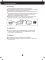
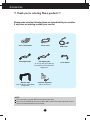
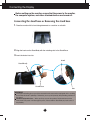
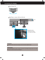
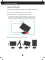
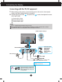
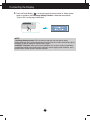
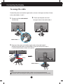
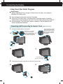
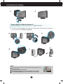
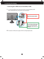
User's Guide
PX2491W
Make sure to read the Important Precautions before using the
product. Keep the User's Guide(CD) in an accessible place for future
reference.
See the label attached on the product and give the information to
Planar's customer service representative should you require
assistance.
Important Precautions
This unit has been engineered and manufactured to ensure your personal safety,
however improper use may result in potential electrical shock or fire hazards. In
order to allow the proper operation of all safeguards incorporated in this display,
observe the following basic rules for its installation, use, and servicing.
On Safety
Use only the power cord supplied with the unit. If you use another power cord,
make sure that it is certified by the applicable national standards when not
provided by the supplier. If the power cable is faulty in any way, please contact the
manufacturer or the nearest authorized repair service provider for a replacement.
The appliance coupler is used as the disconnect device.
Please make sure the device is installed near the wall outlet to which it is
connected and that the outlet is easily accessible.
Operate the display only from a power source indicated in the specifications of this
manual or listed on the display. If you are not sure what type of power supply you
have in your home, consult with your dealer.
Overloaded AC outlets and extension cords are dangerous. So are frayed power
cords and broken plugs. They may result in a shock or fire hazard. Contact Planar
Customer Service for a replacement cord.
As long as this unit is connected to the AC wall outlet, it is not disconnected from
the AC power source even if the unit is turned off.
Do not Open the Display:
There are no user serviceable components inside.
There are Dangerous High Voltages inside, even when the power is OFF.
Contact Planar if the display is not operating properly.
To Avoid Personal Injury :
Do not place the display on a sloping shelf unless properly secured.
Use only a stand recommended by the manufacturer.
Do not drop an object on or apply impact to the product. Do not throw any toys
or objects on the product screen.
It can cause injury to human, problem to product and damage the display.
To Prevent Fire or Hazards:
Always turn the display OFF if you leave the room for more than a short period
of time. Never leave the display ON when leaving the house.
Keep children from dropping or pushing objects into the display's cabinet
openings. Some internal parts carry hazardous voltages.
Do not add accessories that have not been designed for this display.
When the display is to be left unattended for an extended period of time, unplug
it from the wall outlet.
In the presence of thunder and lightning, never touch the power cord and signal
cable because it can be very dangerous. It can cause electric shock.
1
Important Precautions
On Installation
Do not allow anything to rest upon or roll over the power cord, and do not place the
display where the power cord is subject to damage.
Do not use this display near water such as near a bathtub, washbowl, kitchen sink,
laundry tub, in a wet basement, or near a swimming pool.
Displays are provided with ventilation openings in the cabinet to allow the release
of heat generated during operation. If these openings are blocked, built-up heat
can cause failures which may result in a fire hazard. Therefore, NEVER:
Block the bottom ventilation slots by placing the display on a bed, sofa, rug, etc.
Place the display in a built-in enclosure unless proper ventilation is provided.
Cover the openings with cloth or other material.
Place the display near or over a radiator or heat source.
Do not rub or strike the Active Matrix LCD with anything hard as this may scratch,
mar, or damage the Active Matrix LCD permanently.
Do not press the LCD screen with your finger for a long time as this may cause
some afterimages.
Some dot defects may appear as Red, Green or Blue spots on the screen.
However, this will have no impact or effect on the display performance.
If possible, use the recommended resolution to obtain the best image quality for
your LCD display. If used under any mode except the recommended resolution,
some scaled or processed images may appear on the screen. However, this is
characteristic of the fixed-resolution LCD panel.
Leaving a fixed image on the screen for a long time may cause damage to the
screen and cause image burn-in. Make sure to use a screen saver on the product.
Burn-in and related problems are not covered by the warranty on this product.
Do not shock or scratch the front and sides of the screen with metallic objects.
Otherwise, it may cause damage to the screen.
Make sure the panel faces forward and hold it with both hands to move. If you
drop the product, the damaged product can cause electric shock or fire. Contact
Planar for repair.
Avoid high temperatures and humidity.
2
Important Precautions
On Cleaning
Unplug the display before cleaning the face of the display screen.
Use a slightly damp (not wet) cloth. Do not use an aerosol directly on the display
screen because over-spraying may cause electrical shock.
When cleaning the product, unplug the power cord and scrub gently with a soft
cloth to prevent scratching. Do not clean with a wet cloth or spray water or other
liquids directly onto the product. An electric shock may occur. (Do not use
chemicals such as benzene, paint thinners or alcohol)
Spray water onto a soft cloth 2 to 4 times, and use it to clean the front frame;
wipe in one direction only. Too much moisture may cause staining.
On Repacking
Do not throw away the carton and packing materials. They make an ideal
container in which to transport the unit. When shipping the unit to another
location, repack it in its original material.
On Disposal
Do not dispose of this product with general household waste.
Disposal of this product must be carried out in accordance to the regulations of
your local authority.
3
Accessories
!!! Thank you for selecting Planar products !!!
Please make sure the following items are included with your monitor.
If any items are missing, contact your reseller.
User's Guide/Cards
DVI-D Signal Cable
Power Cord
DVI-I Signal Cable
(To set it up, this signal cable may
be attached to this product before
shipping out.)
Monitor Hood
(Not included in StereoMirror
configuration).
USB Cable
Cable Holder
Calibrator (Spyder3)
(optinal accessory)
NOTE
This accessories may look different from those shown here.
User must use shielded signal interface cables (DVI-I cable, DVI-D cable) with ferrite cores to
maintain standard compliance for the product.
4
Connecting the Display
Before setting up the monitor, ensure that the power to the monitor,
the computer system, and other attached devices are turned off.
Connecting the stand base or Removing the stand base
1. Place the monitor with its front facing downward on a cushion or soft cloth.
2. Align the hooks on the Stand Body with the matching slots in the Stand Base.
3. Insert the hooks into slots.
Hook
Stand Body
Stand Base
Slot
WARNING
The tape and locking pin may only be removed from those monitors equipped with a standing
base when the base is pulled up. Otherwise, you may be injured by the protruding sections of
the stand.
Handle Product with Care. : When you lift up or move the product, Do Not hold or touch the
front part of LCD panel. It will damage the panel. (Please hold the Stand Body or plastic cover of
the product.)
5
Connecting the Display
4.
Attach the monitor to the Stand Base by turning the screw to the right.
Screw : Turn the screw by using the screw handle.
5. Lift and turn the monitor to face towards the front after the connection is
made to the female part of the cable you're attaching.
6. Take the screw out by turning to the left to separate the monitor and Stand
Base.
IMPORTANT
This illustration depicts the general model of connection. Your monitor may differ from the items
shown in the picture.
Do not carry the product upside down holding only the stand base. The product may fall and get
damaged or injure your foot.
Positioning your display
After installation, adjust the angle as shown below.
1. Adjust the position of the panel in various ways for maximum comfort.
Tilt Range : -6˚ to 22˚
-6
22
When adjusting the angle of the
screen, do not put your finger(s) in
between the head of the monitor
and the stand body. You can hurt
your finger(s).
6
Connecting the Display
Swivel Range : 350˚
350
Height Range : maximum 100.0 mm (3.94 inch)
100.0 mm
* Please be sure to
remove the Locking
pin to adjust the height.
WARNING
You do not need to replace the Locking pin after it is removed, to adjust its height.
ERGONOMIC
It is recommended that in order to maintain an ergonomic and comfortable viewing position, the forward tilt
angle of the monitor should not exceed 5 degrees.
7
Connecting the Display
Using the Pivot function
-The pivot function allows you to rotate the screen 90 degrees clockwise.
1. Lift the monitor to its highest height to utilize the Pivot function.
2. Landscape & Portrait : You can rotate the panel 90
o
clockwise.
Please be cautious and avoid contact between the monitor head and the
Stand Base when rotating the screen to access the Pivot function. If the
monitor head touches the Stand Base, then the Stand Base could crack.
Head section
Stand section
3. Be careful with the cables when rotating the screen.
8
Connecting the Display
Connecting with the PC/AV equipment
1. Before setting up the monitor, ensure that the power to the monitor, the computer
system, and other attached devices is turned off.
and power cord
of the signal cable.
2. Connect signal input cable 1
2
in order, then tighten the screw
A Connect DVI-I Cable
B Connect DVI-D Cable
C Connect HDMI Cable
NOTE
This is a simplified representation of the rear view.
This rear view represents a general model; your display may differ from the view as shown.
The HDMI-DVI cable is not compatible with the DVD player or others.
HDMI Headphone Output
Headphone
/Earphone
Connect the signal
input cable and
tighten it up by
turning in the
direction of the
arrow as shown in
the figure.
Varies according to model.
Wall-outlet type
AV equipment (Set-Top Box, DVD,
Video,Video Game Console)
* HDMI is optimized for AV equipment.
* HDMI is not for PC use.
Do not connect the commercial
Digital-to-Analog converter to the
DVI-I cable, because it may not
be compatible.
9
Connecting the Display
3. Press the Power Button (
) on the front panel to turn the power on. When monitor
power is turned on, the 'Self Image Setting Function' is executed automatically.
(Only for DVI-I analog signal cable input)
NOTE
‘ Self Image Setting Function’? This function provides the user with optimal display
settings.When the user connects the monitor for the first time, this function automatically adjusts
the display to optimal settings for individual input signals.
‘AUTO/SET’ Function? When you encounter problems such as blurry screen, blurred letters,
screen flicker or tilted screen while using the device or after changing screen resolution, press
the AUTO/SET function button to improve resolution.
10
Connecting the Display
To arrange the cables
Connect the power cord and the signal cable as shown in the figure and then fix them
to the cable holders 1 and 2.
1.
2.
Please put the power cord and
the signal cable in the cable holder 1.
Please insert the cable holder1
into the hole.
Cable holder 1
3.
Please put the power cord and the signal cable in the cable holder 2.
While pressing the bottom of cable holder 2 with one hand, pull the top of
it with the other hand as shown in the picture.
Pull
Press
Cable holder 2
NOTE
Use the cable holder to organize the cables in order to use the pivot function properly.
This picture shows how to organize cables generally and may look different from your product.
11
Connecting the Display
Using True Color Finder Program
2
1
Requirements
• Windows 2000(Service Pack 4 or higher), XP(Service Pack 2 or higher), Vista, Windows 7
• Macintosh OS X(10.0 to 10.5)
10
1.
2.
11
3.
3
4
5
After installing the monitor hood, insert the CD provided.
Click on the [True Color Finder] -> [Installation] icons to install the program. For detailed
method on how to use the program, refer to the True Color Finder manual in the provided CD.
After executing the "True Color Finder" program, connect the Calibrator(Spyder3) to the
monitor and computer respectively.
6
Connecting and Disconnecting the Monitor Hood
12
1.
After cross inserting, putting
'8' latch into the groove and
pushing it towards an arrow
direction, please assemble
by pressing from number 9
to number 12.
Connect the Monitor Hood as shown below.
After inserting '1' latch into
the groove and pushing it
towards an arrow direction,
please assemble by pressing
from number 2 to number 6.
3
4
5
2
6
2
3
4
5
1
2
13
8
9
10
11
7
8
7
7
9
8
12
4
3
10
10
11
11
12
12
1
2
13
A click will be 13
heard
9
5
6
1
6
2.
7
1
6
3
4
5
(optinal accessory)
when the clip engages.
To disconnect the monitor hood, follow the steps in the reverse order.
7
12 13
611 54
10 3
8
1
12
2
12 13
11
10
8
10
9
3
2
Connecting
the Display
8
12 13
11
10
9
8
12 13
11
10
8
Connecting the Calibrator(Spyder3) (optinal accessory)
Connect the Calibrator(Spyder3) to the monitor as shown below. Tilt the monitor to maximum of
16° to the rear to use the Calibrator (Spyder3).
1
2
1
1
2
2
AUDIO
OUT
AUDIO
OUT
1.
16
NOTE
Do not put excessive pressure on the monitor hood when fitting. It may
damage the hood.
Do not put any objects on the hood.
With the hood installed, do not shake it or rotate the screen(Pivot).
The Calibrator (Spyder3) may not be provided for some models.
13
Connecting the Display
Connecting the USB(Universal Serial Bus) Cable
You can use the USB port at the back of the monitor to connect peripherals (USB
mouse, USB keyboard, etc.) to the monitor, not to the computer.
2
1.
1
Four USB Downstream ports
Connect these ports to a mouse,
memory stick or USB hard disk.
One USB Upstream port
Connect this port to the downstream
port of a computer, laptop or USB
monitor (Your computer or USB
monitor must support USB and have
USB ports).
2. The monitor’s USB terminal supports USB 2.0 and High Speed cables.
14
Control Panel Functions
Front Panel Controls
MODE Button
Use this button to move to items in COLOR MODE
(CUSTOM, sRGB, ADOBE RGB, CALIBRATION,
EMULATION, PLNR).
For more information, refer to page 20 to 21.
MENU Button
Use this button to enter or exit the On Screen Display.
OSD LOCKED/UNLOCKED
This function allows you to lock the current control settings,
so that they cannot be inadvertently changed. Press and
hold the MENU button for several seconds. The message
"OSD LOCKED" should appear.
You can unlock the OSD controls at any time by pushing the
MENU button for several seconds. The message "OSD
UNLOCKED" should appear.
15
Control Panel Functions
Buttons
Use these buttons to select or adjust functions in the
On Screen Display.
To adjust the headphone/earphone volume. Press the
AUTO/SET button to MUTE ON and press it once
again to MUTE OFF. (Only for HDMI input)
MUTE OFF
Use the
buttons to adjust the volume.
MUTE ON
(SOURCE Hot key)
AUTO/SET
Button
When two or more input signals are connected, you
can select the input signal (DVI-I/DVI-D/HDMI) you
want. When only one signal is connected, it is
automatically detected.
The default input signal is DVI-I (analog).
Use this button to enter a selection in the On Screen
Display.
AUTO IMAGE ADJUSTMENT
When adjusting your display settings, always press the
AUTO/SET button before entering the On Screen
Display(OSD). (Only for DVI-I analog signal cable input)
This will automatically adjust your display image to the
ideal settings for the current screen resolution size
(display mode).
The best display mode is
1920 x 1200
Power Button
Use this button to turn the display on or off.
Power Indicator
The power indicator stays red if the display is running
properly (On Mode). If the display is in Sleep Mode
(Energy Saving), the power indicator is blinking red.
16
On Screen Display (OSD) Control Adjustment
Screen Adjustment
Making adjustments to the image size, position and operating
parameters of the display is quick and easy with the On Screen
Display Control system.
A short example is given below to familiarize you with the use of the
controls. The following section is an outline of the available
adjustments and selections you can make using the OSD.
To make adjustments in the On Screen Display, follow these steps:
Pops up the
menu screen
Move where
you want to
adjust
Select a
menu icon
Adjust the
status
Exit from the
menu screen.
1
Press the MENU Button, then the main menu of the OSD appears.
2
To access a control, use the
or
Buttons. When the icon you want
becomes highlighted, press the AUTO/SET Button.
3
Use the
/ Buttons to adjust the image to the desired level.
Use the AUTO/SET Button to select other sub-menu items.
4
Press the MENU Button once to return to the main menu to select another
function. Press the MENU Button twice to exit from the OSD.
17
On Screen Display(OSD) Selection and Adjustment
The following table indicates all the On Screen Display control, adjustment,
and setting menus.
DVI-I(A) : DVI-I(Analog) signal
DVI-I(D) : DVI-I(Digital) signal
DVI-D
Main menu
COLOR MODE
Sub-menu
: DVI-D(Digital) signal
Supported signals
Description
CUSTOM
DVI-I(A)
DVI-I(D)
DVI-D
HDMI(Y)
HDMI(R)
The default mode that adjusts the
overall range of colors of the RGB
LED panel.
sRGB
DVI-I(A)
DVI-I(D)
DVI-D
HDMI(R)
Adjusts colors based on sRGB.
ADOBE RGB
DVI-I(A)
DVI-I(D)
DVI-D
HDMI(R)
Adjusts colors based on ADOBE
RGB.
CALIBRATION
DVI-I(A)
Adjusts Color features by
controlling the Brightness,
WhitePoint and Gamma values
through the color management
system (CMS).
DVI-I(D)
DVI-D
EMULATION
DVI-I(A)
DVI-I(D)
DVI-D
Adjusts Color features by
controlling the Brightness,
WhitePoint , RGB Color Gamut
and Gamma values through the
color management system (CMS).
DVI-I(A)
DVI-I(D)
DVI-D
HDMI(Y)
HDMI(R)
Color features are pre-set for 255
monotonic gray levels.
BRIGHTNESS
CONTRAST
GAMMA
DVI-I(A)
DVI-I(D)
DVI-D
HDMI(Y)
HDMI(R)
Standard image settings.
BLACK LEVEL
HDMI(Y)
HDMI(R)
WHITE BALANCE
DVI-I(A)
PLNR
PICTURE
HDMI(Y) : HDMI (YUV) signal
HDMI(R) : HDMI (RGB) signal
18
On Screen Display(OSD) Selection and Adjustment
COLOR
COLOR TEMP
(PRESET)
(USER)
5000K
6500K
7200K
8200K
9300K
RED
GREEN
BLUE
HUE
SATURATION
SIX COLOR
(RED/GREEN/
BLUE/CYAN/
MAGENTA/
YELLOW)
DVI-I(A)
DVI-I(D)
DVI-D
HDMI(Y)
HDMI(R)
Color temperature adjustments
COLOR RESET
TRACKING
HORIZONTAL
DVI-I(A)
VERTICAL
CLOCK
DVI-I(A)
PHASE
SETUP
SHARPNESS
DVI-I(A)
DVI-I(D)
DVI-D
HDMI(Y)
HDMI(R)
HORIZONTAL MIRRORING
DVI-I(A)
DVI-I(D)
DVI-D
HDMI(Y)
HDMI(R)
LANGUAGE
DVI-I(A)
DVI-I(D)
DVI-D
HDMI(Y)
HDMI(R)
OSD POSITION
(HORIZONTAL / VERTICAL)
Adjusts the position of the
screen
Adjusts the clarity and stability
of the screen
To adjust to set the image
mirroring(horizontal inversion).
Additional settings
HDMI(Y)
HDMI(R)
OVERSCAN
ARC
DVI-I(A)
DVI-I(D)
DVI-D
HDMI(Y)
HDMI(R)
RTC
POWER INDICATOR
FACTORY RESET
NOTE
The order of icons may differ depending on the model (18 to 27).
19
On Screen Display(OSD) Selection and Adjustment
The OSD screen will appear when you press the MODE button on the front
of the monitor.
DVI Input
HDMI(RGB) Input
HDMI(YUV) Input
*When HDMI(RGB) is inputted, CUSTOM, sRGB, ADOBE RGB and PLNR mode are supported.
*When HDMI(YUV) is inputted, CUSTOM and PLNR mode are supported.
MENU : Exit
: Move
AUTO/SET : Select
Main menu
CUSTOM
Description
The default mode that adjusts the overall range
of colors of the RGB LED panel. You can
adjust the color functions of the main menu.
* In modes other than CUSTOM mode, you
cannot adjust the PICTRUE
(CONTRAST,GAMMA) and COLOR
functions of the main menu.
sRGB
Color features are set for sRGB specification.
Color Temperature, Brightness, Gamma and x
and y coordinates of RGBCMY are adjusted
based on the sRGB specification.
20
On Screen Display(OSD) Selection and Adjustment
Main menu
ADOBE RGB
Description
Color features are set for Adobe RGB
specification.
Color Temperature, Brightness, Gamma and x
and y coordinates of RGBCMY are adjusted
based on the Adobe RGB specification.
CALIBRATION Adjusts Color features by controlling the
Brightness, WhitePoint and Gamma values
through the color management system (CMS).
* This function is available only after 'True
Color Finder' is installed on the computer
and calibration has been performed with the
calibrator.
EMULATION
Adjusts Color features by controlling the
Brightness, WhitePoint , RGB Color Gamut
and Gamma values through the color
management system (CMS).
* This function is available only after 'True
Color Finder' is installed on the computer
and calibration has been performed with the
calibrator.
PLNR
Color features are preset for 255 monotonic
levels of gray.
21
On Screen Display(OSD) Selection and Adjustment
You were introduced to the procedure of selecting and adjusting an item
using the OSD system. Listed below are the icons, icon names, and icon
descriptions of the all items shown on the Menu.
Press the MENU Button, then the main
menu of the OSD appears.
Main Menu
MENU
: Exit
: Adjust (Decrease/Increase)
SET
: Enter
: Select another sub-menu
Button Tip
: Restart to select sub-menu
Menu Name
Submenus
Icons
NOTE
OSD (On Screen Display) menu languages on the monitor may differ from the manual.
22
On Screen Display(OSD) Selection and Adjustment
Main menu
Sub menu
Description
PICTURE
BRIGHTNESS
To adjust the brightness of the screen.
CONTRAST
To adjust the contrast of the screen.
GAMMA
Set your own gamma value.
: 1.8 to 2.4
On the monitor, high gamma values
display whitish images and low gamma
values display blackish images.
HDMI Input
BLACK LEVEL You can set the offset level. If the black
level value becomes higher, the screen
grows brighter. If the value becomes
lower, the screen grows darker.
(Only for HDMI input)
MENU : Exit
: Decrease
: Increase
SET : Select another sub-menu
* Offset? As the criteria for video signal, it
is the darkest screen the monitor
can show.
WHITE
BALANCE
If the output of the video card is different
than the required specifications, the color
level may deteriorate due to video signal
distortion. Using this function, the signal
level is adjusted to fit into the standard
output level of the video card in order to
provide the optimal image.
Activate this function when white and
black colors are present in the screen.
(Only for DVI-I analog input)
23
On Screen Display(OSD) Selection and Adjustment
Main menu
Sub menu
Description
COLOR
PRESET Mode
USER Mode
Use the
COLOR TEMP Select either PRESET or USER to
adjust the screen color.
PRESET
Select the preset color temperature.
5000K to 6500K: Yellow screen color.
6500K to 7200K: Red screen color.
8200K to 9300K: Blue screen color.
USER
A user can create screen color by
adjusting RED, GREEN and BLUE.
Set your own red color levels.
RED
GREEN
BLUE
HUE
Adjusts the screen hue.
SATURATION
Adjusts the color sharpness on the
screen. Lower values make the color
sharpness weaker and colors lighter
while higher values make the color
sharpness stronger and colors darker.
SIX COLOR
Sets and stores the hue and saturation
for six colors(RED/GREEN/BLUE/CYA
N/MAGENTA/YELLOW) to satisfy the
color requirements of a user.
COLOR
RESET
Resets the color settings to the factory
default settings for the current input
device.
button to go to sub-menu.
MENU : Exit
: Decrease
: Increase
SET : Select another sub-menu
24
On Screen Display(OSD) Selection and Adjustment
Main menu
Sub menu
Description
TRACKING
HORIZONTAL To move image left and right.
MENU : Exit
: Decrease
: Increase
SET : Select another
sub-menu
VERTICAL
To move image up and down.
CLOCK
To minimize any vertical bars or
stripes visible on the screen
background.
The horizontal screen size will also
change.
PHASE
To adjust the focus of the display.
This item allows you to remove any
horizontal noise and clear or sharpen
the image of characters.
SHARPNESS
To adjust the clearness of the screen.
HORIZONTAL
MIRRORING
Adjust to activate or disable
mirroring(horizontal inversion).
25
On Screen Display(OSD) Selection and Adjustment
Main menu
Sub menu
Description
SETUP
DVI Input
MENU : Exit
: Adjust
: Adjust
SET : Select another
sub-menu
LANGUAGE
To choose the language in which the
control names are displayed.
OSD
POSITION
To adjust position of the OSD window
on the screen.
OVERSCAN
Removes noise that may occur at the
edges of an image when HDMI is
connected to an external device. When
ON is selected, the image size is
reduced to prevent noise. When OFF is
selected, the original image size is
maintained regardless of noise. (Only
for HDMI input)
ARC
Sets the screen size.
- FULL: Fits the screen to the panel size.
- ORIGINAL: Adjusts the aspect ratio
automatically depending on input
image signal.
-1:1: Changes the aspect ratio to 1:1
depending on input image signal.
FULL
ORIGINAL
1:1
* ARC is disabled when the input signal
has the recommended resolution of
1920 x 1200.
26
On Screen Display(OSD) Selection and Adjustment
Main menu
Sub menu
Description
SETUP
HDMI Input
MENU : Exit
: Adjust
: Adjust
SET : Select another
sub-menu
RTC
If you set ON, you enable the Response
Time Control function and reduce the
afterimage of the screen.
If you set OFF, you disenable the
Response Time Control function and
operate at panel response time.
POWER
INDICATOR
Use this function to set the power
indicator on the front side of the monitor
to ON or OFF.
If you set OFF, it will go off.
If you set ON at any time, the power
indicator will automatically be turned on.
FACTORY
RESET
Restore all factory default settings except
'LANGUAGE' and the color settings of
'CALIBRATION', 'EMULATION' mode.
Press the , buttons to reset
immediately.
NOTE
If this does not improve the screen image, restore the factory default settings. If necessary, execute the
white balance function again. The White Balance function is available only when the input signal is DVI-I
(Analog).
27
Troubleshooting
Check the following before calling for service.
No image appears
● Is the power cord of the • Check and see if the power cord is connected
properly to the power outlet.
display connected?
● Is the power indicator
light on?
• Press the Power button.
● Is the power on and the • Adjust the brightness and the contrast.
power indicator red?
● Is the power indicator
blinking?
• If the display is in power saving mode, try moving
the mouse or pressing any key on the keyboard to
bring up the screen.
• Try to turn on the PC.
● Do you see an "OUT OF • This message appears when the signal from the
PC (video card) is out of horizontal or vertical
RANGE" message on
frequency range of the display. See the
the screen?
'Specifications' section of this manual and
configure your display again.
● Do you see a "CHECK
SIGNAL CABLE"
message on the
screen?
• This message appears when the signal cable
between your PC and your display is not
connected. Check the signal cable and try again.
Do you see a "OSD LOCKED" message on the screen?
● Do you see “OSD
LOCKED” when you
push MENU button?
• You can secure the current control settings,
so that they cannot be inadvertently changed.
You can unlock the OSD controls at any time
by pushing the MENU button for several
seconds: the message
“OSD UNLOCKED” will appear.
28
Troubleshooting
Display image is incorrect
● Display Position is
incorrect.
• Press the AUTO/SET button to automatically
adjust your display image to the ideal setting.
If the results are unsatisfactory, adjust the image
position using the H position and V position icon
in the on screen display.
● On the screen
background, vertical
bars or stripes are
visible.
• Press the AUTO/SET button to automatically
adjust your display image to the ideal setting.
If the results are unsatisfactory, decrease the
vertical bars or stripes using the CLOCK icon in
the on screen display.
● Any horizontal noise
appearing in any
image or characters
are not clearly
portrayed.
• Press the AUTO/SET button to automatically
adjust your display image to the ideal setting.
If the results are unsatisfactory, decrease the
horizontal bars using the PHASE icon in the on
screen display.
• Check Control Panel --> Display --> Settings
and adjust the display to the recommended
resolution or adjust the display image to the ideal
setting. Set the color setting higher than 24 bits
(true color).
IMPORTANT
Check Control Panel --> Display --> Settings and see if the frequency or the resolution were
changed. If yes, readjust the video card to the recommend resolution.
If the recommended resolution (optimal resolution) is not selected, letters may be blurred and the
screen may be dimmed, truncated or biased. Make sure to select the recommend resolution.
The setting method can differ by computer and O/S (Operation System),
and resolution mentioned above may not be supported by the video card
performance. In this case, please contact Planar.
29
Troubleshooting
Display image is incorrect
● The screen color is
mono or abnormal.
• Check if the signal cable is properly connected
and use a screwdriver to fasten if necessary.
• Make sure the video card is properly inserted in
the slot.
• Set the color setting higher than 24 bits (true color)
at Control Panel - Settings.
● The screen blinks.
• Check if the screen is set to interlace mode and if
yes, change it to the recommend resolution.
Do you see an "Unrecognized monitor, Plug&Play (VESA
DDC) monitor found" message?
● Have you installed the
display driver?
• Be sure to install the display driver from the display
driver CD (or diskette) that comes with your
display. Or, you can also download the driver from
our web site: http://www.planar.com.
• Make sure to check if the video card supports
Plug&Play function.
The Audio function is not working
● Picture OK & No sound.
• Check whether volume is "0".
• Check sound muted.
• HDMI cable installed properly.
• Head phone cable installed properly.
• Check sound format. Not supply to compressed
sound format.
30
Specifications
Display
60.96 cm (24.0 inch) Flat Panel Active matrix-TFT LCD
Anti-Glare coating
Visible diagonal size : 60.96 cm
0.270 mm x 0.270 mm (Pixel Pitch)
Sync Input
Horizontal Freq.
Vertical Freq.
Input Form
30 kHz to 83 kHz (Automatic)
56 Hz to 75 Hz (Automatic)
Separate Sync.
Digital
Video Input
Signal Input
DVI-I Connector (Analog, Digital)
DVI-D Connector (Digital), HDMI Connector(Video)
RGB Analog, Digital, HDMI
Input Form
Resolution
Max
Recommend
VESA 1920 x 1200 @ 60 Hz
DVI-I/DVI-D Input : VESA 1920 x 1200 @ 60 Hz
HDMI(Video) Input : VESA 1920 x 1080 @ 60 Hz
Plug&Play
DDC 2B
Power
Consumption
On Mode
Sleep Mode
Off Mode
Dimensions
& Weight
With Stand
Width 56.01 cm (22.05 inch)
Height 44.66 cm (17.58 inch) (Min.)
54.66 cm (21.52 inch) (Max.)
Depth 27.02 cm (10.64 inch)
:
≤
≤
64 W (Typ.)
2 W (DVI-I Input)
1W
Weight(excl. packing)
Without Stand
Width 56.01 cm (22.05 inch)
Height 37.21 cm (14.65 inch)
Depth
9.55 cm ( 3.76 inch)
9.6 kg (21.16 lb)
10.5 kg (23.15 lb)(With Hood)
Range
Tilt
Swivel
Height
Power Input
AC 100-240 V~ 50 / 60 Hz 0.9 A
-6˚ to 22˚
350˚
100 mm ( 3.94 inch)
31
Specifications
Environmental
Conditions
Operating Conditions
Temperature
10 ˚C to 35 ˚C
Humidity
10 % to 80 % non-Condensing
Storage Conditions
Temperature
-20 ˚C to 60 ˚C
Humidity
5 % to 90 % non-Condensing
Stand Base
Attached (
Power cord
Wall-outlet type
USB
Standard
USB 2.0, Self-Power
Data Rate
Max 480 Mbps
Power Consumption
Max 2.5 W x 4
), Detached ( O )
NOTE
Information in this document is subject to change without notice.
32
Specifications
Preset Modes (Resolution) - DVI INPUT
Display Modes (Resolution)
1
2
3
4
5
6
7
8
9
10
11
12
13
14
15
16
*17
640 x 480
640 x 480
720 x 480
720 x 400
800 x 600
800 x 600
1024 x 768
1024 x 768
1152 x 864
1280 x 768
1280 x 768
1280 x 1024
1280 x 1024
1600 x 1200
1680 x 1050
1680 x 1050
1920 x 1200
VGA
VESA
VESA
VGA
VESA
VESA
VESA
VESA
VESA
VESA
VESA
VESA
VESA
VESA
VESA
VESA
VESA
Horizontal Freq. (kHz)
31.469
37.500
35.162
31.500
37.879
46.875
48.363
60.023
67.500
47.776
60.289
63.981
79.976
75.000
64.674
65.290
74.038
Vertical Freq. (Hz)
59.940
75.000
59.901
70.156
60.317
75.000
60.004
75.029
75.000
59.870
74.893
60.020
75.025
60.000
59.883
60.454
59.950
*Recommend Mode
HDMI VIDEO INPUT
Display Modes (Resolution)
1
2
3
4
5
6
7
8
Horizontal Freq. (kHz)
Vertical Freq. (Hz)
31.50
31.25
37.50
45.00
28.12
33.75
56.25
67.50
60.00
50.00
50.00
60.00
50.00
60.00
50.00
60.00
480p
576p
720p
720p
1080i
1080i
1080p
1080p
Indicator
MODE
On Mode
Sleep Mode
Off Mode
LED Color
Red
Red Blinking
Off
33
Installing the Wall mount plate
This monitor satisfies the specifications of the Wall mount plate or
the interchange device.
1. After moving the product to face
downward, make sure to place it on a
soft cloth or a cushion to avoid surface
damage.
2. Separate the head and the stand with
the use of a screwdriver.
3. Install the Wall mount plate.
Wall mount plate (Separate purchase)
- Be sure to use screws and a wall mount that meet
VESA standards.
- Using screws longer than those recommended might
damage the product.
- Using screws that do not meet VESA standards might
either damage the product or result in it coming away
from the wall.We will not be held responsible for any
damage resulting from failure to follow these
instructions.
Kensington Security Slot
Connected to a locking cable that can be purchased
separately at most computer stores.
Wall Mount pad
< Screw Mounting Interface Dimension >
Hole spacing : 100 mm x 100 mm
NOTE
VESA compatible only with respect to screw mounting interface dimensions and mounting screw
specifications
Please use VESA standard as below.
* 784.8 mm and under (30.9 inch)
- Wall Mount Pad Thickness : 2.6 mm
- Screw : 4.0 mm x Pitch 0.7 mm x Length 10 mm
* 787.4 mm and above (31.0 inch)
- Please use VESA standard wall mount pad and screws.
34
Planar System's Inc.
1195 NW Compton Drive
Beaverton, OR 97006
(503)748-1195
(866)-Planar1 (752-6271)
[email protected]
2010, Planar Systems, Inc. Planar is a registered trademark of Planar Systems, Inc. All other
trademarks are property of their respective owners. Technical information in this document is subject to
change without notice. Please consult your account manager for up to date and/or custom
configurations.