1
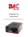
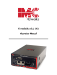
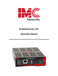
iMcV-DS3/E3/STS Repeater
Operation Manual
FCC Radio Frequency Interference Statement
This equipment has been tested and found to comply with the limits for a Class B computing device, pursuant to Part 15 of the FCC Rules.
These limits are designed to provide reasonable protection against harmful interference when the equipment is operated in a commercial
environment. This equipment generates, uses and can radiate radio frequency energy and, if not installed and used in accordance with the
instruction manual, may cause harmful interference to radio communications. Operation of this equipment in a residential area is likely to
cause harmful interference in which the user will be required to correct the interference at his own expense.
Any changes or modifications not expressly approved by the manufacturer could void the user’s authority to operate the equipment.
The use of non-shielded I/O cables may not guarantee compliance with FCC RFI limits. This digital apparatus does not exceed the Class B
limits for radio noise emission from digital apparatus set out in the Radio Interference Regulation of the Canadian Department of
Communications.
Le présent appareil numérique n’émet pas de bruits radioélectriques dépassant les limites applicables aux appareils numériques de classe B
prescrites dans le Règlement sur le brouillage radioélectrique publié par le ministère des Communications du Canada.
Warranty
IMC Networks warrants to the original end-user purchaser that this product, EXCLUSIVE OF SOFTWARE, shall be free
from defects in materials and workmanship under normal and proper use in accordance with IMC Networks'
instructions and directions for a period of six (6) years after the original date of purchase. This warranty is subject to the
limitations set forth below.
At its option, IMC Networks will repair or replace at no charge the product which proves to be defective within such
warranty period. This limited warranty shall not apply if the IMC Networks product has been damaged by
unreasonable use, accident, negligence, service or modification by anyone other than an authorized IMC Networks
Service Technician or by any other causes unrelated to defective materials or workmanship. Any replaced or repaired
products or parts carry a ninety (90) day warranty or the remainder of the initial warranty period, whichever is longer.
To receive in-warranty service, the defective product must be received at IMC Networks no later than the end of the
warranty period. The product must be accompanied by proof of purchase, satisfactory to IMC Networks, denoting
product serial number and purchase date, a written description of the defect and a Return Merchandise Authorization
(RMA) number issued by IMC Networks. No products will be accepted by IMC Networks which do not have an RMA
number. For an RMA number, contact IMC Networks at PHONE: (800) 624-1070 (in the U.S. and Canada) or (949)
465-3000 or FAX: (949) 465-3020. The end-user shall return the defective product to IMC Networks, freight, customs
and handling charges prepaid. End-user agrees to accept all liability for loss of or damages to the returned product
during shipment. IMC Networks shall repair or replace the returned product, at its option, and return the repaired or
new product to the end-user, freight prepaid, via method to be determined by IMC Networks. IMC Networks shall not
be liable for any costs of procurement of substitute goods, loss of profits, or any incidental, consequential, and/or
special damages of any kind resulting from a breach of any applicable express or implied warranty, breach of any
obligation arising from breach of warranty, or otherwise with respect to the manufacture and sale of any IMC Networks
product, whether or not IMC Networks has been advised of the possibility of such loss or damage.
EXCEPT FOR THE EXPRESS WARRANTY SET FORTH ABOVE, IMC NETWORKS MAKES NO OTHER WARRANTIES,
WHETHER EXPRESS OR IMPLIED, WITH RESPECT TO THIS IMC NETWORKS PRODUCT, INCLUDING WITHOUT
LIMITATION ANY SOFTWARE ASSOCIATED OR INCLUDED. IMC NETWORKS SHALL DISREGARD AND NOT BE
BOUND BY ANY REPRESENTATIONS OR WARRANTIES MADE BY ANY OTHER PERSON, INCLUDING EMPLOYEES,
DISTRIBUTORS, RESELLERS OR DEALERS OF IMC NETWORKS, WHICH ARE INCONSISTENT WITH THE
WARRANTY SET FORTH ABOVE. ALL IMPLIED WARRANTIES INCLUDING THOSE OF MERCHANTABILITY AND
FITNESS FOR A PARTICULAR PURPOSE ARE HEREBY LIMITED TO THE DURATION OF THE EXPRESS WARRANTY
STATED ABOVE.
Every reasonable effort has been made to ensure that IMC Networks product manuals and promotional materials
accurately describe IMC Networks product specifications and capabilities at the time of publication. However, because
of ongoing improvements and updating of IMC Networks products, IMC Networks cannot guarantee the accuracy of
printed materials after the date of publication and disclaims liability for changes, errors or omissions.
ii
Table of Contents
FCC Radio Frequency Interference Statement ....................................................ii
Warranty............................................................................................................ii
About the iMcV-DS3/E3/STS ............................................................................. 1
Configuration .................................................................................................... 1
DIP Switches..................................................................................................... 3
Installation ........................................................................................................ 4
LEDs ................................................................................................................. 5
Feature Descriptions ......................................................................................... 5
Loopback Testing .............................................................................................. 8
Pseudorandom Bit Sequence (PRBS) Testing...................................................... 9
Installation Troubleshooting............................................................................. 10
Specifications .................................................................................................. 10
IMC Networks Technical Support.................................................................... 11
Electrostatic Discharge Precautions.................................................................. 11
Safety Certifications......................................................................................... 12
iii
About the iMcV-DS3/E3/STS
iMcV-DS3/E3/STS is an SNMP-manageable module which converts thin coax
signals to single-mode or multi-mode fiber signals at a data rate of 45 Mbps (DS3),
34 Mbps (E3) or 52 Mbps (STS). Each iMcV-DS3/E3/STS, BNC/FX module
includes one pair of BNC connectors and one pair of ST or SC fiber optic
connectors. This module must be installed in either, an SNMP-manageable
iMediaChassis chassis or an unmanaged MediaChassis chassis.
Also available for single-strand fiber, iMcV-DS3/E3/STS, BNC/SSFX includes one
pair of BNC connectors and an SC fiber optic connector. iMcV-DS3/E3/STS,
BNC/SSFX modules allow two wavelengths, for example, (1310 nm and 1550 nm)
to share one fiber strand, essentially doubling the capacity of installed fiber.
iMcV-DS3/E3/STS modules must be deployed in pairs (one at each end of a
conversion). The data transmitted on the fiber ports can only be received and
interpreted by the receive fiber of another iMcV-DS3/E3/STS. The single strand
versions must have opposite transmit and receive wavelengths (for example one
that transmits at 1310 nm must be paired with another that receives at 1550 nm).
Configuration
Proper configuration of the iMcV-DS3/E3/STS is required for maximum
performance and reliability. The following sections describe the prerequisites and
the configurations available for both managed and unmanaged modules.
Prerequisites
The iMcV-DS3/E3/STS is designed to conform to many DS3/E3/STS-based
environments. Make sure that all of the relevant information about the expected
installation environment is available before configuring the module. This
information includes the following:
• Distance of the coax run
• Distance of the fiber run
• Troubleshooting requirements.
Managed Modules
To manage iMcV-DS3/E3/STS modules, an SNMP agent must be present; the
iMediaChassis requires an SNMP management module. For a managed
environment, first manually configure all of the desired DIP Switch selectable
features to match what will be configured through the SNMP Management
Module.
Use the Graphical User Interface (GUI) to enable features by using the iView2
SNMP management software. In a managed chassis, the software settings take
priority over the SNMP enabled feature DIP Switch settings. Make sure that the
software settings match the desired configuration requirements for the installation.
iView² Management Software
iView² is the IMC Networks management software designed specifically for the
IMC Networks “iMcV” family of modules. It features a GUI and gives network
managers the ability to monitor and control the manageable IMC Networks
products.
iView² is available in several versions and can also function as a snap-in module
for HP OpenView Network Node Manager and other third party SNMP
Management software. For assistance in selecting the right version of iView² for
your operating system, please visit:
http://www.imcnetworks.com/products/iview2.cfm
iView2 supports the following platforms:
•
•
•
Windows NT
Windows 2000
Windows XP
In addition, there are Java versions of iView² for any Java-capable operating
systems such as Linux.
Please see the SNMP Management Module for software configuration options.
NOTE
IMC Networks’ iView2 software is available for downloading from the web site:
www.imcnetworks.com.
Unmanaged Modules
Before installing the module in an unmanaged chassis, including IE-MediaChassis
series and MediaChassis series, manually configure all of the desired DIP Switch
selectable features. In an unmanaged configuration, none of the DIP Switch
settings can be overridden by software.
2
DIP Switches
The iMcV-DS3/E3/STS DIP Switches are located on S1 and S2 on the PCB. The
S2 DIP Switches are factory configured and must not be moved. The S1 DIP
Switches provide control over the available iMcV-DS3/E3/STS features.
The location of the S1 DIP Switches is displayed in the following diagram:
3
DIP Switch Settings
FUNCTION
SWITCH SETTINGS
RESULT [(D) = Default]
2
Loopback (iView Configurable)
S1-1: OFF
S1-1: ON
Loopback Type (iView2 Configurable)
S1-2: OFF
S1-2: ON
Jitter Attenuation (iView2 Configurable)
S1-3: OFF
S1-3: ON
FiberAlert (iView2 Configurable)
S1-4: OFF
S1-4: ON
Line Build-Out (iView2 Configurable)
S1-5: OFF
S1-5: ON
Transmit Data Source (iView2 Configurable)
S1-6: ON 7: ON
S1-6: OFF 7: ON
S1-6: ON 7: OFF
S1-6: OFF 7: OFF
DS3/E3/STS Selection
S1-8: ON 9: OFF
S1-8: OFF 9: ON
S1-8: ON 9: ON
Remote Management
S1-10: OFF
S1-10: ON
Loopback Disabled (D)
Loopback Enabled
Coax (D)
Fiber
Jitter Attenuator on Receive Side
Jitter Attenuator on Transmit Side (D)
FiberAlert Disabled (D)
FiberAlert Enabled
0 to 255 ft.
> 255 ft. (D)
Standard Data (D)
Unframed All Ones
Alternating Ones & Zeros
Pseudorandom Bit Sequence
45 Mbps (DS3)
34 Mbps (E3)
52 Mbps (STS)
Remote Management Disabled (D)
Remote Management Enabled
Installation
iMcV-DS3/E3/STS modules can be installed in any iMediaChassis, MediaChassis
or IE-MediaChassis series (remote modules can also be installed in any
unmanaged MediaChassis series). Each module requires one slot in the chassis.
To install a module, remove the blank brackets covering the slots where the
module is to be installed (if present) by removing the screws on the outside edges
of the bracket. Slide the module into the chassis card guides, until the module is
securely seated in the connector. Secure the module to the chassis by tightening
the captive screw. Save any blanks removed during installation for future use.
NOTE
It is not recommended that the iMcV-DS3/E3/STS module be installed in an 850-33100.
The power source in this chassis is not isolated, and cannot support positive reference
ground systems typically used in Telco environments.
4
LEDs
The iMcV-DS3/E3/STS module features several diagnostic LEDs per port. The
LED functions are as follows:
LEDs Next to Coax (BNC) Port
LPBK
Glows green when module is in a Loopback mode.
NO LNK
Glows green when a link is NOT established.
PBEO
When Transmit Data Source is set to Pseudorandom Bit Sequence, this LED will glow yellow
when iMcV-DS3/E3/STS receives a Pseudorandom
Bit Sequence with errors. The LED stays off when
the converter receives a Pseudorandom Bit
Sequence without errors. When Transmit Data
Source is set to any other configuration besides
Pseudorandom Bit Sequence, this LED remains off
as well.
LEDs Next to Fiber Optic Port
FA
Glows green when FiberAlert is enabled.
NO LNK
Glows green when a link is NOT established.
RM
Glows green on the remote unit when Remote
Management is enabled. Glows green on the local
unit when it has discovered a manageable remote
unit.
SYM
Glows yellow when a FX symbol error has occurred.
Feature Descriptions
The iMcV-DS3/E3/STS module includes several features that allow it to be
configured for varying DS3/E3/STS-based environments.
Loopback
This switch enables or disables the loopback feature. When this feature is
enabled, the data line (Coax or Fiber) set by the Loopback Type DIP Switch is
looped back.
By default this feature is set to DISABLED.
This feature can be controlled by SNMP management software (iView2) when the
iMcV-DS3/E3/STS module is installed in a managed chassis.
5
Loopback Type
This switch controls which data line is looped back when the Loopback DIP
Switch is enabled. The data line loopback selection can be either Fiber Loopback
or Coax Loopback.
By default this feature is set to COAX.
This feature can be controlled by SNMP management software (iView2) when the
iMcV-DS3/E3/STS module is installed in a managed chassis.
Jitter Attenuation
This switch selects the jitter attenuation location on the coax transceiver. The
jitter attenuation can be set on the transmit side or on the receive side of the coax
transceiver.
Jitter attenuation is useful for decreasing jitter in the coax data stream. This helps
prevent data degradation caused by jitter. Jitter attenuation is always enabled.
By default this feature is set to TRANSMIT.
This feature can be controlled by SNMP management software (iView2) when the
iMcV-DS3/E3/STS module is installed in a managed chassis.
FiberAlert
This switch enables or disables the FiberAlert feature. This feature must only be
enabled on the remote end of a Host/Remote iMcV-DS3/E3/STS pair.
The FiberAlert feature uses the iMcV-DS3/E3/STS module LEDs to indicate that a
loss of one strand of fiber has occurred. When a strand becomes unavailable, the
iMcV-DS3/E3/STS module at the receiver-end detects the loss of the link. The
module then responds by stopping the transmission of the data and link signal
until a new signal or link pulse is received on the strand. The result is that the NO
LNK LED on both sides of the fiber connection will light up to indicate the
presence of a fault somewhere in the fiber loop. By using FiberAlert, a local site
administrator can quickly determine where a fiber cable fault is located.
By default this feature is set to DISABLED.
This feature can be controlled by SNMP management software (iView2) when the
iMcV-DS3/E3/STS module is installed in a managed chassis.
** WARNING **
Enabling FiberAlert on both of the iMcV-DS3/E3/STS modules will cause them both to stop
transmitting unrecoverably when a fault occurs. This feature is designed to only be
enabled on the Remote iMcV-DS3/E3/STS module.
6
Transmit LIU Waveshape (Line Build-Out)
This switch selects the optimal transmit waveshape for the line build-out distance
on the coax line. The transmit waveshape can be set for a distance of either 0 to
255 feet or over 255 feet. This feature corrects problems related to cabling (i.e.
cross-talk, electromagnetic interference, etc.). Improperly setting this switch will
cause signal degradation.
By default this feature is set to > 255 FEET.
This feature can be controlled by SNMP management software (iView2) when the
iMcV-DS3/E3/STS module is installed in a managed chassis.
Transmit Data Source
These switches select the transmit mode used by the iMcV-DS3/E3/STS module.
The transmit modes that can be selected include the following:
•
•
•
•
Standard data
Unframed All Ones (diagnostic)
Alternating Ones and Zeros (diagnostic)
Pseudorandom bit sequence (diagnostic)
These standard Telco transmission pattern modes are provided to help diagnose
transmission errors in the line.
By default this feature is set to STANDARD DATA.
This feature can be controlled by SNMP management software (iView2) when the
iMcV-DS3/E3/STS module is installed in a managed chassis.
DS3, E3 and STS Selection
This switch selects the data rate to use on the coax line. The data rate selections
available include the following:
•
•
•
45 Mbps (DS3)
34 Mbps (E3)
52 Mbps (STS)
By default this feature is set to 45 Mbps (DS3).
This feature can only be selected by setting the DIP Switches manually.
Remote Management
This switch enables or disables the Remote Management mode. Enabling Remote
Management on the Remote module allows all SNMP-configurable features for
both the Host and Remote modules to be configured from the Host module.
7
NOTE
When the Remote Management feature is enabled on the Remote module, the remote
module must either be installed in an unmanaged chassis or in a managed chassis with the
SNMP-management disabled (iMediaChassis chassis with the SNMP management module
removed).
By default this feature is set to Disabled.
This feature can only be selected by setting the DIP Switches manually.
Loopback Testing
The iMcV-DS3/E3/STS includes two loopback test modes: Coax Loopback and
Fiber Loopback.
The following illustrations show the path that a signal takes in each of the
loopback test modes.
Each loopback performs the following:
• Redirects the incoming signal back out to the origin while continuing to
transmit downstream.
• Blocks downstream data from arriving on the looped data line.
Loopback testing is useful for troubleshooting problems with network connections
should they occur. Looping received data back onto the transmit path helps
determine whether a connection is still valid. Remote loopback tests isolate
problems on the coax run between an iMcV-DS3/E3/STS module and the
connected device, while local loopback tests can isolate problems on the fiber
connected to the module.
8
The following illustrations show a typical progression of loopback tests (i.e. starting
by checking the coax segment at the local side, then the coax segment at the
remote side, etc).
Pseudorandom Bit Sequence (PRBS) Testing
To test using Pseudorandom Bit Sequence, configure the iMcV-DS3/E3/STS
modules for No Loopback, then configure the Transmit Data Source to “Transmit
Pseudorandom Bit Sequence.” Configure the local device for loopback, conduct
the test, then check the PBEO LED to verify errors were not received (Refer to the
LED section for more information).
9
Installation Troubleshooting
General Troubleshooting
• During installation, first test the fiber and BNC connections with all
troubleshooting features disabled; then enable these features, if desired, just
before final installation. This will reduce the features’ interference with
testing.
• When working with units where the features cannot be disabled, you must
establish BOTH your BNC and fiber connections; the NO LNK LEDs should
not be lit (i.e. NO LNK LED not lit = good connection, NO LNK LED lit =
problem).
• To test a media converter by itself, first make sure you have an appropriate
fiber patch cable, then follow these steps to test:
1. Connect the media converter to the BNC device with a coax cable.
2. Loop a single strand of fiber from the transmit port to the receive port of
your media converter.
3. Verify that you have a valid connection for both the BNC and fiber ports
on your media converter.
• If there is trouble with link connectivity, make sure the connection is made
using 75W Coax cable.
Specifications
Power Consumption (Typical)
0.550 Amps @ 5 V
Operating Temperature
32° to 122° F (0° to 50° C)
Storage Temperature
0° to 160°F (-20° to 70° C)
Humidity
5 to 95% (non-condensing); 0 to 10,000 ft. altitude
Dimensions
4.19” x .78” x 2.75”
(106.4 mm x 19.81 mm x 69.85 mm)
10
IMC Networks Technical Support
Tel: (949) 465-3000 or (800) 624-1070 (in the U.S. and Canada);
+32-16-550880 (Europe)
Fax: (949) 465-3020
E-Mail: [email protected]
Web: www.imcnetworks.com
Fiber Optic Cleaning Guidelines
Fiber Optic transmitters and receivers are extremely susceptible to contamination by
particles of dirt or dust, which can obstruct the optic path and cause performance
degradation. Good system performance requires clean optics and connector ferrules.
1.
Use fiber patch cords (or connectors, if you terminate your own fiber) only from a
reputable supplier; low-quality components can cause many hard-to-diagnose
problems in an installation.
2.
Dust caps are installed at IMC Networks to ensure factory-clean optical devices.
These protective caps should not be removed until the moment of connecting the
fiber cable to the device. Should it be necessary to disconnect the fiber device,
reinstall the protective dust caps.
3.
Store spare caps in a dust-free environment such as a sealed plastic bag or box so that
when reinstalled they do not introduce any contamination to the optics.
4.
If you suspect that the optics have been contaminated, alternate between blasting
with clean, dry, compressed air and flushing with methanol to remove particles of
dirt.
Electrostatic Discharge Precautions
Electrostatic discharge (ESD) can cause damage to any product, add-in modules or stand
alone units, containing electronic components. Always observe the following precautions
when installing or handling these kinds of products
1.
Do not remove unit from its protective packaging until ready to install.
2.
Wear an ESD wrist grounding strap before handling any module or component. If
the wrist strap is not available, maintain grounded contact with the system unit
throughout any procedure requiring ESD protection.
3.
Hold the units by the edges; do not touch the electronic components or gold
connectors.
4.
After removal, always place the boards on a grounded, static-free surface, ESD pad or
in a proper ESD bag. Do not slide the modules or stand alone units over any surface.
WARNING! Integrated circuits and fiber optic components are extremely
susceptible to electrostatic discharge damage. Do not handle these components
directly unless you are a qualified service technician and use tools and techniques
that conform to accepted industry practices.
11
Safety Certifications
UL/CUL: Listed to Safety of Information Technology Equipment, including
Electrical Business Equipment.
CE: The products described herein comply with the Council Directive
on Electromagnetic Compatibility (2004/108/EC) and the Council
Directive on Electrical Equipment Designed for use within Certain
Voltage Limits (2006/95/EC). Conforms to UL Std. 60950-1;
Certified to CSA Std. C22.2 No. 60950-1
3178738
Class 1 Laser product, Luokan 1 Laserlaite,
Laser Klasse 1, Appareil A’Laser de Classe 1
European Directive 2002/96/EC (WEEE) requires that any equipment that bears
this symbol on product or packaging must not be disposed of with unsorted
municipal waste. This symbol indicates that the equipment should be disposed of
separately from regular household waste. It is the consumer’s responsibility to
dispose of this and all equipment so marked through designated collection
facilities appointed by government or local authorities. Following these steps
through proper disposal and recycling will help prevent potential negative
consequences to the environment and human health. For more detailed
information about proper disposal, please contact local authorities, waste disposal
services, or the point of purchase for this equipment.
12
19772 Pauling • Foothill Ranch, CA 92610-2611 USA
TEL: (949) 465-3000 • FAX: (949) 465-3020
www.imcnetworks.com
© 2009 IMC Networks. All rights reserved.
The information in this document is subject to change without notice. IMC Networks assumes no responsibility for any
errors that may appear in this document. iMcV-DS3/E3/STS Repeater is a trademark of IMC Networks. Other brands or
product names may be trademarks and are the property of their respective companies.
Document Number 50-80301-00 A4
August 2009