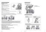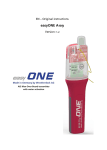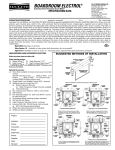
1
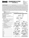
Hardware Kits
A101, A105, A109, A111
Form E-364
Rev. 08 / 10
Caution: These fasteners should be installed by
qualified personnel into a surface that is capable of
supporting a static load of four times the combined weight
of the audio/visual device and mount. Do not attach to
plaster, paneling or drywall alone.
Required Tools:
-
-
9/16” wrench
Drill motor
Drill bits
Hammer
Solid Concrete Hardware Kit –A101
1. Remove contents from carton and
examine for damaged or missing parts.
See Figure 1.
2. Drill a 5/8” diameter hole into the concrete
wall surface to the screw length. Blow the
hole clean of dust and debris.
3. Make sure the threaded cone is snug
onto the anchor so that the cone will stay
on the anchor during installation. Insert
the anchor, cone first, into the hole and
tap it in place so that the top edge is flush
with the concrete surface.
4. Position the mount and insert the screw to
engage the cone and tighten the screw
until secure. The screw should engage a
minimum of 2/3 of the threads. Use a flat
washer where applicable.
Figure 1
Wood Stud Hardware Kit –A105
1. Remove contents from carton and
examine for damaged or missing parts.
See Figure 2.
2. Drill a 3/16” diameter hole through the
wall surface and into a stud to the depth
of the screw length.
3. Position the mount, insert the screw and
tighten until secure. Use a flat washer
where applicable.
Figure 2
Hollow Block/Steel Stud Hardware Kit –A109
1. Remove contents from carton and
examine for damaged or missing parts.
See Figure 3.
2. Drill a 3/4” diameter hole through the wall
surface and into the structural part of the
wall to accommodate the required
fastener length.
3. Fold the metal channel flat to the plastic
straps and slide the channel through the
hole in the wall. Allow channel to “unfold”
inside of the wall. Make sure the channel
is vertically positioned when used on steel
studs. Pull plastic loop toward yourself so
channel is flush behind wall and slide cap
down the plastic straps until cap is against
the wall. Break plastic straps off at the
cap by placing thumb in between the
straps and on the cap and sliding thumb
side to side.
4. Position the mount, insert the screw and
tighten until secure. Use a flat washer
where applicable.
Figure 3
Metal Joist/Beam Hardware Kit –A111
1. Remove contents from carton and examine
for damaged or missing parts. See Figure 4.
2. Drill a 7/16” diameter hole through the steel
base material.
3. Position the mount, insert the screw, thread
on nut and tighten until secure. Use a flat
washer where applicable.
Figure 4