1
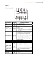
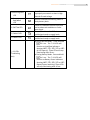
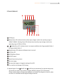
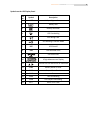
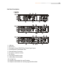
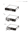
power your future℠ ROCWAVE Intelligent True On‐Line UPS User Manual 1,000 VA 2,000 VA 3,000 VA ROCPOWER ‐ ROCWAVE user manual Table of Contents IMPORTANT SAFETY INSTRUCTIONS ..................................................4 CHAPTER 1 ...........................................................................................6 LED Panel (Standard) ...........................................................................6 LCD panel (Optional) ............................................................................8 Symbols on the LCD Display Panel.......................................................9 Real Panel Descriptions......................................................................10 CHAPTER 2 .........................................................................................11 Unpacking ..........................................................................................11 Installation Location...........................................................................12 Storage Instructions...........................................................................13 Maintenance ......................................................................................13 CHAPTER 3 .........................................................................................14 Set up .................................................................................................14 Tower Configuration Setup................................................................14 Power Module + Battery Module ......................................................15 Rack‐Mount Configuration Setup ......................................................16 CHAPTER 4 .........................................................................................18 Operational Test ................................................................................18 LED panel (Standard) .........................................................................18 Status & Alarm Buzzer .......................................................................28 CHAPTER 5 .........................................................................................29 Replacing the Battery.........................................................................29 Recycling the Used Battery ................................................................31 CHAPTER 6 .........................................................................................32 Product Introduction .........................................................................32 General Characteristics......................................................................32 Special Features .................................................................................33 Operating Modes & Voltage System Configurations.........................34 System Configuration Settings...........................................................34 Programmable outlet setting.............................................................36 Communication Port Explanation......................................................38 True RS232 Port Descriptions ............................................................38 USB Port Descriptions ........................................................................39 EPO …………………………………………………..……………………………………………39 2 ROCPOWER ‐ ROCWAVE user manual CHAPTER 7 .........................................................................................40 How the UPS works............................................................................40 UPS System Block Diagram ................................................................40 When Utility is Normal.......................................................................41 When Utility is Abnormal/Absent......................................................42 Overload Condition............................................................................43 CHAPTER 8 .........................................................................................46 Bundle Software Installation Guide ...................................................46 Hardware Installation ........................................................................46 Optional Communication Cards.........................................................47 R2E (2nd RS‐232) card........................................................................47 USE (USB) card ...................................................................................47 DCE (Dry Contact) card ......................................................................48 SNMP Cards........................................................................................49 SNMP/WEB card…………………………………………………………………………….49 SNMP card of Megatec…………………………………………………………………..49 CHAPTER 9 .........................................................................................50 Troubleshooting.................................................................................50 CHAPTER 10……………………………………………..……………………………….. 55 Specifications .....................................................................................53 CHAPTER 11 .......................................................................................57 LIMITED WARRANTY ..........................................................................57 TECHNICAL SUPPORT INFORMATION ................................................62 Trademarks Acknowledgements .......................................................63 Copyrights ..........................................................................................63 Contact Information...........................................................................64 3 ROCPOWER ‐ ROCWAVE user manual IMPORTANT SAFETY INSTRUCTIONS PLEASE, SAVE THESE INSTRUCTIONS This manual contains important instructions that should be followed during unpacking, installation and maintenance of the UPS and batteries. Important Notices • To ensure safety in all applications where a UPS is hard‐wired to the electrical supply, the connections between the UPS and the electrical supply should be made by a qualified electrical contractor. • Those UPS systems supplied with a factory input lead can be safely connected to the wall outlet by the purchaser. • The UPS has its own internal energy source (battery). Should the battery be switched on when no AC power is available, voltage will be at the output terminals. • Ensure that the AC utility outlet is correctly wired and grounded. • Ensure that the input voltage of the UPS matches the supply voltage. • Use a certified input power cable with the correct plugs and sockets that matches the voltage system. • Do not open the case as there are no serviceable parts inside. Opening the case will void the warranty. • Any attempt to repair the UPS unit by someone other than an authorized technician shall void the warranty. • To eliminate overheating of the UPS, keep all ventilation openings free from obstruction, and do not store anything on top of the UPS. Keep the UPS 8 inches (20 cm) away from the wall. • Ensure the UPS is installed within the proper environment as specified (0‐40°C or 32‐40o F and 30‐90% non‐condensing humidity). • Do not install the UPS in direct sunlight. The warranty may be void if the batteries fail. • Install the UPS indoors as it is not designed for outdoor use. • Dusty, corrosive and salty environments can damage the UPS. • Install the UPS away from objects which give off excessive heat and areas which are excessively wet. • Liquids spilled and/or foreign objects dropped into the UPS will void the warranty. • The battery will discharge naturally if the system is unused for any length of time. • The UPS should be recharged every 2‐3 months if unused. If this is not done, the warranty will be void. When the UPS is used regularly, the batteries will be automatically recharged and kept in top condition. • This UPS has been designed and constructed to protect your assets from the wide range of power aberrations experienced on utility power lines. Take care to install and maintain the system correctly by your local distributor. • Intended for installation in a temperature controlled environment. 4 ROCPOWER ‐ ROCWAVE user manual • Servicing of batteries should be performed or supervised by persons knowledgeable about batteries and the required precautions. Keep unauthorized personnel away from batteries. • When replacing batteries, replace with the same number and type. CAUTION – Do NOT dispose of battery or batteries in a fire. The battery may explode. CAUTION – Do NOT open or mutilate the battery or batteries. Released electrolyte is harmful to the skin and eyes. It may be toxic. CAUTION – Risk of Electric Shock – Do NOT remove the cover. There are no user serviceable parts. Refer servicing to qualified technicians. CAUTION – Risk of Electric Shock – The battery circuit is NOT isolated from AC. Hazardous voltage may exist between the battery terminals and ground. Test before touching. CAUTION – A battery can present a risk of electrical shock and high short circuit current. CAUTION – Keep children away from this product. CAUTION – HEALTH CARE – THE UPS IS NOT TO BE USED IN PATIENT CARE APPLICATIONS: The Rocpower product you purchased was not designed for direct or indirect patient care and treatment. DO NOT use this product with any equipment used to directly or indirectly treat or care for a patient. CAUTION – To prevent personal injury or property damage, do not carry or move the UPS by the handle or the front cover. CAUTION – The UPS is designed to be used with computer loads only. CAUTION – Do NOT connect a laser printer to the UPS outlets. The Following precautions should be observed when working on batteries: • Remove watches, rings, or other metal objects. • Use tools with insulated handles. • Wear rubber gloves and boots. • Do not lay tools or metal parts on top of batteries. • Disconnect charging source prior to connecting or disconnecting battery terminals. WARNING: • This is a Class A‐UPS Product in a domestic environment • This product may cause radio interference. Should this occur, the user may be required to take additional measures. 5 ROCPOWER ‐ ROCWAVE user manual CHAPTER 1 LED Panel (Standard) Control Keypads Symbols 1. ON 2. OFF 3. Self‐Test (Alarm Silence) ◎ Manual Bypass Functional Descriptions UPS Power‐On Switch UPS Power‐Off Switch a. Command the UPS to perform self‐ testing b. Alarm Silence ‐ To mute the alarm buzzer (Press & hold for > 1 sec) Press OFF key and Self‐Test key simultaneously for approx. 3 seconds to transfer from Inverter to Bypass (the bypass LED continuously “blinks” and the + buzzer will beep intermediately) or transfer from Bypass to Inverter, when the UPS is on Line Mode and the Bypass Voltage is Normal. LED Indicators 4. Normal Mode LED 5. Battery Mode LED 6. Bypass Mode LED 7. Overload LED 8. Fault LED Symbols Functional Descriptions (Color) LED indicates utility voltage within tolerance (120Vac~280Vac) (Color) LED indicates utility outage or out of tolerance loads supplied by battery power (Color) LED indicates bypass supply is normal Red LED indicates UPS is overloaded Red LED indicates fault or abnormal conditions 6 ROCPOWER ‐ ROCWAVE user manual 9. Site wiring fault LED Red LED indicates Live & Neutral lines are improperly connected or there is High Neutral‐Ground voltage 10. Battery Bad/Weak LED Red LED indicates low battery power or faulty battery bank 11. Self Test LED 12. Outlet2 LED 13. Outlet1 LED 7~11 LEDs (% Indicating Bars) Green LED indicates successful self‐test and no abnormal conditions or faults were found Green LED indicates 2 UPS Outlets are enabled and ready to supply loads Green LED indicates 1 UPS Outlet is enabled and ready to supply loads a. During Normal Mode:Press and hold for 1 sec. The 7~11 LEDs will function as Load Rate indicators showing 100%, 75%, 50%, 25% or 10% of UPS capacity . These LEDs will stop illuminating after 10 sec. b. During Battery Mode: Press and hold for 1 sec. The 7~11 LEDs will function as Battery Power indicators showing 100%, 75%, 50%, 25% or 10% Battery Power remaining. These LEDs will stop illuminating after 10 sec. 7 ROCPOWER ‐ ROCWAVE user manual LCD panel (Optional) LCD Display Steady Green LED indicates that the utility input voltage is within the operating range of 160VAC~288VAC; Flashing Green LED indicates that the utility input voltage is within the operating range of 120Vac~159Vac. 、 Steady Green LED indicates there is an output available at the Programmable Outlet 1 & Programmable Outlet 2. Steady Amber LED indicates the Bypass Input is normal. UPS Fault LED UPS ON/Alarm Silence UPS OFF Switch Special functions log in/out Go to next page Go to previous page or change the setting of the UPS. To re‐confirm the change of UPS Setting ◎ Manual Bypass: Press ON‐KEY and Up‐KEY key simultaneously for approximately three (3) seconds to transfer from Inverter to Bypass Mode (the bypass LED continuously “blinks“ and the buzzer will beep intermediately ) or transfer from Bypass to Inverter, when the UPS is on Line Mode and the Bypass Voltage is Normal. 8 ROCPOWER ‐ ROCWAVE user manual Symbols on the LCD Display Panel Ite Symbol m 1 LINE 2 3 5 Site Wiring Fault UPS Working in Service Mode 7 OFF UPS Shutoff 8 FAIL UPS Abnormal Lock 9 10 11 Battery Low UPS Overloading 6 Utility or Bypass Source Battery Abnormal 4 Description UPS Flow Chart 4 Digit Measurement Display Indicate the item desired to be measured 22 Er05 Battery Weak or Dead 23 Er06 Output Short Circuit 24 Er10 Inverter Over‐current 25 Er11 UPS Overheating 26 Er12 UPS Output Overloading 27 Er** Other Error Code 9 ROCPOWER ‐ ROCWAVE user manual Real Panel Descriptions 120V 5 6 4 1KVA 1 2 3 10 8 7 2KVA 3KVA 1. USB Port 2. RS232 Port 3. Emergency Power Off (EPO) Dry Contact Signal inputs 4. Communication Card Options Slot 5. External Battery Connector 6. AC power connection socket 7. AC Outlets 8. Two programmable outlets 9. Utility Input circuit breaker 10. Cooling Fans 11. Output circuit breaker for two (2) outlets 12. Output circuit breaker for two (2) programmable outlets 10 ROCPOWER ‐ ROCWAVE user manual CHAPTER 2 Please read the Safety Instructions (pages 2 to 3) before installing the UPS. Unpacking CAUTION: Please be careful when lifting the shipping container or the UPS. These items are heavy. Improper lifting or movement may cause personal injuries or property damage. • Take the UPS out of the packing material. Retain it for future use. • Inspect the UPS for any obvious damage. If damage exits, IMMEDIATELY contact the hipper. • Standard package includes: 1 User Manual. 2pcs of IEC output cables (for UPS with IEC sockets only) 1 AC Input Power Cord 1 set of UPS communication software with RS232 cable 1 set of Tower/Rack Accessories Kit as below: Optional Optional 11 ROCPOWER ‐ ROCWAVE user manual Installation Location It is necessary to select a proper environment to install the unit, in order to minimize the possibility of damage to the UPS and extend the life of the UPS. Please follow the instructions below: 1. Keep minimum 20cm (8 inches) distance clearance from the rear panel of the UPS to avoid any obstructions. 2. Do not block the air‐flow to the ventilation opening of the unit. 3. Please ensure the installation site is free from excessive dust and the ambient temperature and humidity should be within the specified limits. 4. Do not place the UPS in a dusty or corrosive environment or near any flammable objects. 5. This UPS is not designed for outdoor use. Relative Humidity (non- condensing) 0%~90% 12 ROCPOWER ‐ ROCWAVE user manual Storage Instructions For extended storage in moderate climate, the batteries should be charged for 12 hours every three (3) months by connecting the UPS to the utility supply and switch on input breaker located at UPS rear panel. Repeat this procedure every two (2) months if the storage ambient temperature is above 30°C (86°F). Maintenance Clean the dust from the ventilation openings and intakes on the rear panel. 1. Turn OFF the UPS and wipe the casing with a damp cloth. 2. Periodically unplug the UPS power cord from the wall Outlet to test the batteries. 3. Be sure you have already saved all applications before you proceed to the battery discharging capability test. 13 ROCPOWER ‐ ROCWAVE user manual CHAPTER 3 Set up Tower Configuration Setup Step 1 S2 Step 2 S1 S1 14 ROCPOWER ‐ ROCWAVE user manual Power Module + Battery Module Step 1 Step 2 S1 15 ROCPOWER ‐ ROCWAVE user manual Rack‐Mount Configuration Setup Step 1 Step 2 S2 Step 3 S2 16 ROCPOWER ‐ ROCWAVE user manual Step 4 Step 5 17 ROCPOWER ‐ ROCWAVE user manual CHAPTER 4 Operational Test LED panel (Standard) Start Up in Normal AC Mode NOTE: Charge the UPS for more than eight (8) hours after unpacking to ensure it is fully charged before use. 1. Before commencing the installation, please ensure the UPS is properly grounded. 2. Ensure that the utility voltage matches the input voltage of the UPS. 3. Connect UPS main power cord to the AC utility power outlet. 4. Turn ON the AC power source. All of the LEDs on the front panel display will flash once after three (3) seconds, except 、 which will remain illuminated (Green). At the same time, the fan at the rear of the UPS will start operating. 5. Press the ‘ ’ switch for approximately three (3) seconds to start the UPS. The buzzer will beep and the and , LEDs will light up after 30 seconds. The start‐up procedure is completed and the UPS outlets are available. . 6. It is advisable to perform a Battery Mode Test before connecting the loads to the UPS to ensure the batteries are working properly. 7. Switch OFF the AC power source after the UPS had been switched ON. The LED on the front panel display will turn OFF while the LED will be illuminated. The buzzer alarm will beep intermediately, indicating the UPS is in Battery Mode. Connect a non‐critical load to the UPS outlets to confirm power from the battery. Repeat the test by switching ON and OFF the AC power source to ensure the UPS is functioning properly. Start‐up in Battery Mode (Cold Start) This UPS can be switched ON for operation without the presence of an AC power source. Press and hold the ‘ ’ switch until the buzzer beeps, then release the switch. Within the next 10 seconds, press and hold the ‘ ’ switch a 2nd time. The UPS shall perform its start‐up procedure. The and 、 LEDs will light up after 30 seconds and the buzzer will beep intermediately to indicate successful power ON. 18 ROCPOWER ‐ ROCWAVE user manual Shutdown 1. Shutdown in AC Mode: Press the ‘ ’ switch for approximate five (5) seconds until the buzzer beeps. The UPS will stop power to the outlets. , LEDs will remain illuminated and the ventilating fans will continue to operate. Switch OFF the AC power source. After 10 seconds, the , LEDs will turn OFF and the ventilating fans will stop operating. The UPS is now completely shutdown. 2. Shutdown in DC Mode: ’ switch for approximately five (5) seconds until the buzzer beeps. The UPS will Press the ‘ stop power to the outlets. After 10 seconds, the , LEDs will turn OFF and the ventilating fans will stop operating. The UPS is now completely shutdown. Self ‐Testing during AC Mode After the UPS has been successfully started in AC Mode, press the ‘ ’ switch for approximately five (5) seconds until the buzzer beeps. The LED will blink to indicate self‐test in progress. If there are no faults or abnormal conditions, the LED will stop blinking and will remain illuminated when the self‐test is completed. The LED will automatically turn OFF 30 seconds after the successful self‐test. Start Up In Normal Mode 1. Ensure that the utility voltage matches the input voltage of the UPS. 2. Connect the UPS to the wall outlet of the utility. Turn the UPS switch ON. The and LEDs will light up to indicate the utility and the battery bypass are normal. The LCD will change from drawing A to drawing B. A 19 ROCPOWER ‐ ROCWAVE user manual B 3. The UPS is on Bypass Mode and will automatically conduct to a self‐test. If no abnormal message occurred, it means the pre‐start‐up of the UPS is successful and the charger is charging the batteries. 4. Press the UPS ON switch ‘ ’ for approximately three (3) sec. The Buzzer will sound twice. If the UPS start‐up is successful, the LCD will change from drawing B to drawing C. C 5. If a failure occurs in self‐test, the LCD will display drawing D. An error code or error status will be shown on the screen. D E 20 ROCPOWER ‐ ROCWAVE user manual 6. Your start‐up operation of the UPS is now completed as indicated in drawing E. Ensure that the batteries are fully charged by connecting the UPS to a wall receptacle for at least eight (8) hours. Start‐up in Battery Mode (Cold Start) 1. Ensure that the UPS has already been installed with batteries. 2. Press the UPS ON switch for approximately three (3) seconds. The buzzer will sound twice. The LCD display will change from Drawing A to drawing G. G 3. Press the UPS ON switch for approximately three (3) seconds until the LCD display changes from drawing G to drawing H. The UPS will now be in Self‐Test Mode for about 60 seconds. When the Self‐Test Mode is completed, the UPS will supply power to the outputs as indicated in LCD drawing I. The UPS will automatically turn OFF if the ON switch is pressed within 10 sounds. H I 21 ROCPOWER ‐ ROCWAVE user manual Check Measured Values and Figures detected by UPS If you would like to check the measured values and messages, please use the scroll up and scroll down key pads. When you use the scroll down key pad, the LCD will display the following sequence: Drawing E (Input Voltage) Æ Drawing J (Input Frequency) Æ Drawing K (UPS Output Voltage) Æ Drawing L (UPS Output Frequency) Æ Drawing M (UPS Output Load percentage) Æ Drawing N (UPS Battery Voltage) Æ Drawing O (UPS inner temperature. J K L M 22 ROCPOWER ‐ ROCWAVE user manual N O UPS Default Data and Special Function Execution 1. After the UPS is turned ON successfully, use key pad to change the LCD display screen to drawing P1. P1 P2 2. Press on the key pad to scroll down the LCD screen and then check the UPS settings. The LCD will display the following sequence: Drawing P1 (buzzer) Æ Drawing Q1 (self‐test) 23 ROCPOWER ‐ ROCWAVE user manual Æ Drawing R1 (Bypass Voltage) Æ Drawing S (Output Frequency Synchronized Window) Æ Drawing T (Inverter Output Voltage) Æ Drawing U1 (UPS Operation Mode) Æ Drawing V (Output Voltage Fine Tuning) Q1 Q2 R1 R2 S 24 ROCPOWER ‐ ROCWAVE user manual T U1 U2 U3 V 25 ROCPOWER ‐ ROCWAVE user manual 3. Press the scroll up on the key pad to execute special functions. The functions include Buzzer ON (as drawing Q1) or Buzzer OFF (as drawing Q2, Alarm silence for UPS warning) and Self‐Test OFF (as Drawing R2). The UPS will execute the battery test for 10 seconds. If the Self‐Test is successful, it will show as Drawing W; otherwise, it will show as Drawing D and error message at the same time. W UPS Default Settings and Their Alternatives 1. Ensure the UPS is OFF, which means it is not in Line Mode or Backup Mode. Press the ON Switch and the scroll down key pads simultaneously for approximately three (3) seconds. The buzzer will sound twice. The LCD screen shows drawing P1, which is the Settings Mode. 2. To scroll down the LCD screen, see page 23. 3. All default settings may be changed by pressing scroll up key pad, except the Buzzer (Drawings P1 & P2) and Self‐Test (Q 1 & Q2). 4. The bypass input acceptable range, it can be 176VAC~ 264VAC for 220VAC system, 88VAC~132VAC for 110VAC system or 187VAC~264VAC for 220VAC system, 93.5VAC~132VAC for 110VAC system. 5. Drawing S means: the acceptable setting values of the bypass frequency Inverter Outputs are +/‐3Hz and +/‐1Hz. 6. Drawing T means: the acceptable Inverter Output Voltage is 200V, 208V, 220V, 230V, or 240V for 220VAC system; or 100V, 110V, 115V, 120V and 127V. 7. Drawings U1, U2 and U3 mean: the three operation modes of the UPS is Normal Output, fixed 50Hz Output or fixed 60Hz Output. 8. Drawing V means: the Inverter Output may be calibrated at 0%, +1%, ‐1%, +2%, ‐2%, +3%, or ‐3%. 26 ROCPOWER ‐ ROCWAVE user manual 9. When all the setting changes are completed and Drawing X is displayed, press the enter key pad to save all the changes. The changes will be activated only when the UPS is restarted. The LCD screen will be back to the default screen before setting. X 10. Turn OFF the UPS and the utility input breaker. 11. Your Setting changes are complete. UPS Shuts Down for Unknown Reasons 1. If a serious abnormal condition occurs, the UPS will turn itself OFF as shown in drawing Y. An abnormal message may show in the LCD screen. Y 2. When the UPS turns OFF, it may still provide bypass output in most conditions. See drawing Z. For some special conditions, the UPS will lock itself; however, it may still provide bypass output in most conditions. See Drawing Z, and an error message will be shown on the screen. Z 3. To reset the UPS, please proceed as followings: (a) Read the error message. (b) See Chapter 9 to troubleshoot the problem. If you are unable to reset the UPS, consult your local distributor for service. (c) Press on the key pad for five (5) seconds. The buzzer will sound twice. 27 ROCPOWER ‐ ROCWAVE user manual (d) Turn OFF the utility circuit breaker. (e) The UPS should reset. Shutting OFF the UPS 1. Press on the key pad for about five (5) seconds. The Inverter output will turn OFF. The UPS will stop power supply to the outlets and the LCD screen will show Drawing B. 2. Turn OFF the utility circuit breaker. 3. The UPS is completely turned OFF. Status & Alarm Buzzer The following table helps define the common UPS Status Definitions and Buzzer Beep Descriptions. Status Definitions Buzzer Beep Descriptions UPS faulty, Inverter shutdown. All functions inhabited. UPS faulty, loads continue to be supplied via Inverter or Bypass. Battery Mode Battery low Confirm/RS232 port receiving Service Mode OK UPS initial start‐up within self test Long Continuous Beep Single successive beep within ~ 2 sec Single short successive beep within ~1 sec. Very quick and short successive beep 2 quick & short beeps 1 quick & short beeps 2 successive quick & short beeps, repeating ~2 sec. 28 ROCPOWER ‐ ROCWAVE user manual CHAPTER 5 Replacing the Battery Step 1 Step 2 29 ROCPOWER ‐ ROCWAVE user manual Step 3 Step 4 1KVA 2K/3KVA 30 ROCPOWER ‐ ROCWAVE user manual Recycling the Used Battery Contact your local recycling or hazardous waste center for information on the proper disposal of the used batteries. 31 ROCPOWER ‐ ROCWAVE user manual CHAPTER 6 PRODUCT INTRODUCTION General Characteristics True online technology continuously supplies your critical device with a stable, regulated, transient‐free pure AC sine wave. 1. High‐efficiency Pulse Width Modulation (PWM) sine‐wave topology yields excellent overall performance. The high crest factor of the inverter handles all high in‐rush current loads without the need to upgrade the power rating. 2. User‐friendly Plug‐and‐Play design allows hassle‐free installation. All Rocwave units up to 3,000 VA are supplied with input cables and output sockets as standard. 3. Built‐in Maintenance‐free sealed‐type battery minimises the need for frequent after‐ sales service. 4. To protect the unit from overloading, the UPS will automatically switch to Bypass Mode in 30 seconds if loading is between 105% ~ 120% of rated capacity. It will automatically switch back to Inverter Mode once the overload ceases. 5. Should the output becomes short‐circuited, the UPS puts the system on Stand‐by Mode, provide a visual and audible alarm, and cuts the output supply automatically until the short circuit is manually resolved. 32 ROCPOWER ‐ ROCWAVE user manual Special Features 1. High Frequency Transformer‐less technology with rack/tower convertible enclosure allows use even in the most difficult of environment with space constraints 2. This UPS is equipped with fully digitalized control logic circuit for greater functionality and enhanced high level power protection. Digital signal processing (DSP) also provides powerful communication capability with enhanced flexibility for easy remote control and monitoring 3. Wide input voltage tolerance from 60V ~ 144V (110V version) or 120V~288V (220V version) allows under‐voltage or over‐voltage correction without unnecessary battery drain and helps extend battery life. 4. DC‐start function ensures the start‐up of the UPS even during power outages. 5. Revolutionary battery management circuit analyzes battery discharge status to adjust battery cut‐off point and extend battery life. 6. Active Power Factor Correction (PFC) control function constantly maintains the UPS Input Power Factor (PF) at > 99% for superb energy efficiency. . 7. The UPS has a Selectable Bypass input voltage tolerance (Sensitivity low/high) to prevent under or over voltage being supplied to the loads during Bypass Mode. The selectable Voltage ranges are (i) Sensitivity Low: 92/184~130/260V and (ii) Sensitivity High: 97/194~130/260V. 8. The UPS has Selectable Output Voltages of 100/110/115/120/127V or 200/208/220/230/240 to meet the needs of various voltage systems. 9. The UPS is designed to comply with many stringent international standards for Electromagnetic Interference & protection (EMC). 33 ROCPOWER ‐ ROCWAVE user manual Operating Modes & Voltage System Configurations Download and open the UPS Setting Tool Software to see the screen as below System Configuration Settings 1. System Voltage Selection: Select Input Voltage 110V or 220V 2. Voltage Configurations: Select UPS Output Voltage 100V/110V/115V/120V/127V 3. UPS Modes Select Normal/CF50*/CF60* Mode 4. Output Voltage Fine TuningOutput Voltage Regulation from 0 ~ ± 3% 34 ROCPOWER ‐ ROCWAVE user manual 5. Bypass Voltage Windows: Sensitivity: Select Sensitivity Low/Sensitivity High** Sensitivity Low Sensitivity High 110V 92V~130V 97V~130V System 6. Syn‐Frequency Window: Select 3Hz/1Hz Inverter Freq synchronizing range 7. Com Port: elect the Com Port of PC 8. Click on “Write” to confirm the configuration settings. The UPS will beep twice to acknowledge setting is successful. 9. Turn OFF the UPS after setting is complete to ensure that all the new setting values are written into EEPROM successfully and then re‐start the UPS to enable the new settings. Note: *CF50/CF60 = Frequency Converter Mode 50 to 60Hz or vice versa **Sensitivity Low:92~130V, High: 97~130V 35 ROCPOWER ‐ ROCWAVE user manual Programmable outlet setting The UPS is equipped with two (2) programmable outlets for less critical loads. These outlets can be disabled during back‐up modes or overload conditions to provide power to the more critical loads connected to the UPS. Click on the “Programmable outlet setting” bar to enter the outlet settings screen as shown below. 36 ROCPOWER ‐ ROCWAVE user manual 1. Outlet Turns ON after UPS is Turned ON – select the time to automatically enable this outlet within the specified time when the UPS is powered ON. If “0” seconds is selected, the outlet will be enabled once the UPS is powered ON. 2. Outlet Turns OFF After AC Failure – select this option to automatically disable the outlet within the specified time after the utility outage to provide longer battery back‐up time for the other more critical loads connected to the UPS. 3. Outlet Turns ON After AC Recovers – select this option to automatically enable the outlet within the specified time after the utility is restored. 4. Outlet Turns OFF When Battery Power is Low ‐ select this option to automatically disable the outlet when the remaining battery power capacity (%) is reached during Battery Mode. This will prolong battery back‐up time for the other more critical loads connected to the UPS. 5. Outlet Turns OFF When the UPS Detects an Overload – select this option to automatically disable the outlet during overload condition (Bypass Mode). This allows the more critical loads to be continuously supplied via Bypass Mode. 6. Select the "Settings" menu to configure new parameters. The new setting is confirmed when the UPS beeps twice. Turn OFF the UPS and remove the input source to ensure that the new parameters are successfully written into EEPROM. Then re‐start the UPS to enable the new settings. 7. Manual Control Switch – Click ON or OFF to manually enabled or disabled the programmable outlets, overriding all previous settings. 37 ROCPOWER ‐ ROCWAVE user manual Communication Port Explanation The UPS is equipped with EPO dry contacts input, true RS232 & USB Communication ports as standard. This provides communication with bundled UPS monitoring software for remote monitoring of UPS status via PC. There are four (4) other optional interface cards available to meet various communication needs, i.e., DCE (dry contact relay card), R2E, USE and SNMP/WEB card (see Chapter 8). The UPS bundled software is compatible with many operating systems such as Windows 98, 2000, ME, NT, XP and Vista. For other applications such as Novell, NetWare, UNIX, Linux, please contact your local dealer for suitable software. All the communication ports (including optional cards) can be active and used simultaneously to monitor the UPS status. However, the communication interface with the highest priority has the ability to command and control the UPS. The priority of these communication interfaces are as follows: Highest Priority (in descending order), 1) 2) 3) 4) EPO input port Optional Interface card USB RS232 True RS232 Port Descriptions The RS232 interface has been set as follows: Baud Rate 2400 bps Data Length 8 bits Stop Bit 1 bit Parity None 38 ROCPOWER ‐ ROCWAVE user manual The Pin Assignments of the true RS232 port are illustrated as follows: 5 9 4 8 Pin 3: RS232 Rx 3 7 Pin 2: RS232 Tx 2 6 1 Pin 5: Ground USB Port Descriptions The following is the USB communication protocol definition: 1. Comply with USB version 1.0, 1.5Mbps 2. Comply with USB HID Version 1.0. 3. The Pin Assignments of the USB port: 1 Æ VCC (+5V) 2 Æ D- 3 Æ D+ 4 Æ Ground EPO The Pin assignments of the EPO Input port are: 1 2 1 Æ EPO+ 2 Æ Ground To enable the EPO function, please short Pin 1 & 2. 39 ROCPOWER ‐ ROCWAVE user manual CHAPTER 7 HOW THE UPS WORKS UPS System Block Diagram Fig 1 The above illustrates the True On‐Line Double Conversion architecture of the UPS system. The major modules consist of: 1) An AC to DC power converter (Rectifier) with PFC control circuit 2) A DC to AC high frequency power inverter 3) An Intelligent Battery Charger 4) A bank of stationary maintenance‐free batteries 5) A DC to DC push/pull converter control circuit 6) A Static Bypass Loop 7) Input & Output EMI Filters The table below provides a Summary Guide of the Utility Conditions, UPS Operating Modes and the LED Display Indications. 40 ROCPOWER ‐ ROCWAVE user manual Utility Conditions UPS Operating Modes LEDs Display Indications Rectifier converts AC to DC, battery is charging. Inverter , , LEDs Utility Normal converts DC to AC and supplies are illuminated loads with clean & stable power. Rectifier and charger stop operating,Battery is looped via Utility Abnormal the DC~DC boosts circuit and (under or over provides power to the Inverter. LED OFF, LED voltage) / Loads continue to receive power illuminated Absent from Inverter. The alarm buzzer beeps. The UPS now on Battery Mode. Rectifier and charger stop operating. Battery is looped via Utility the DC~DC boosts circuit and Abnormal/Abse provides power to the Inverter. LED OFF, & LED illuminated. nt, or Battery The alarm buzzer sounds quick low voltage & short beeps, indicating battery power low and Inverter power may soon stop. When Utility is Normal Fig 2 41 ROCPOWER ‐ ROCWAVE user manual The working principle of the UPS under normal utility conditions is illustrated as follows: When the utility is normal, the AC source is rectified into DC. The utility is partially fed into the charger to charge battery and partially fed into the inverter. The inverter changes the DC to AC to supply power to the load connected. The utility LED and inverter LED light up. When Utility is Abnormal / Absent The working principle of the UPS under abnormal utility conditions is illustrated as follows: Fig 3 1. When the utility is abnormal, the UPS will automatically direct the battery power to the inverter and turn OFF the charger and AC/DC converter. The inverter will immediately change DC to AC to supply power to the output load. The LED will be illuminated. 2. When the utility is back to normal, the UPS will turn ON the AC/DC converter, turn OFF the DC/DC converter and switch the charger to Charging Mode. It has the same working principle as Figure 2. 3. During a utility outage, the UPS will work as illustrated in Figure 2. When the battery is low, a buzzer will continuously beep until the battery is completely OFF. The battery low protection circuit of the UPS will shut OFF the battery supply after a preset threshold to avoid over‐ draining the battery. The & (Battery Low) LEDs will light up until the UPS is completely shut OFF. The UPS will automatically restart when the utility is available. 42 ROCPOWER ‐ ROCWAVE user manual Overload Condition The working principle of the UPS when overloaded is illustrated as follows: Fig 4 1. Generally, modern day electronics and IT equipment generate an inrush current when switching on. The amount of inrush current varies from equipment to equipment. Some can be as high as six (6) times its rated capacity while others produce negligible inrush. To prevent severe damage to its inverter caused by the inrush produced by the loads, the UPS is equipped with electronics overload protection feature as standard. If the UPS loading is >105~120% of its capacity, it will switch to Bypass Mode in 30 seconds to protect the inverter. If the overload condition is eliminated by reducing the load to <105%, the UPS will automatically switch back to Inverter Mode. If the UPS loading is > 150% of its capacity, the inverter will immediately shut down. 43 ROCPOWER ‐ ROCWAVE user manual 2. The UPS Bypass loop is also equipped with overload protection. Its overload capacity is illustrated by the graph and table below. Inverter Failure Output Load Short Circuited when power is supplied via the Inverter If the output load is short circuited while being supplied via the inverter, the UPS will automatically shutdown the inverter and stop power to the loads. The fault LED lights up and the buzzer will continuously beep. The UPS will not automatically switch ON after short circuit condition is eliminated. The UPS has to be manually restarted (see page 20, Start Up in Normal Mode). Fig 5 44 ROCPOWER ‐ ROCWAVE user manual Inverter/Internal Overheating If the UPS experiences overheat when the utility is normal, it will switch to Bypass Mode. The UPS will switch back to Inverter Mode when the overheating is eliminated. If it happens when the utility is abnormal, the buzzer will beep continuously and the fault LED will light up. The output of the UPS will also be shut OFF. Inverter Over‐current and Inverter Output Voltage Out of tolerance If the UPS inverter delivers excessive current and voltage, the UPS is out of order. The UPS will switch to Bypass Mode when the utility is abnormal. The utility LED, bypass LED and fault LED will light up. If these two (2) conditions occur when the utility is abnormal, the UPS will turn OFF the output and the fault LED will light up. 45 ROCPOWER ‐ ROCWAVE user manual CHAPTER 8 Bundle Software Installation Guide Hardware Installation 1. Connect the male connector of RS232/USB* cable to the UPS communication port. 2. Connect the female connector of the RS232/USB* cable to a dedicated RS232 port of the Computer. 3. For optional interface cards, please go to the next page for more details. EPO *Note: Only an RS232 cable is provided with the UPS. A USB cable is optional Software Installation Please refer to the user’s manual of the bundled software CD‐ROM for installation guide. 46 G DC 36V 1 2 AC OUTPUT ROCPOWER ‐ ROCWAVE user manual Optional Communication Cards R2E (2nd RS‐232) card CN1 is for RS232 DB9. For communication protocol, please refer to page 39. Installation Position: Optional Slot. USE (USB) card CN1 is for USB. For communicaiton protocol, please refer to page 40. Installation Position: Optional Slot 47 ROCPOWER ‐ ROCWAVE user manual DCE (Dry Contact) card The pin assignments of 10‐Pin Terminal: 1 2 3 4 4 5 6 7 8 9 10 1 Æ UPS on Bypass Mode (Bypass) 2 Æ Utility Normal (Normal close contact) 3 Æ Utility Normal (Normal open contact) 4 Æ Inverter On 5 Æ Battery Low 6 Æ Battery Bad or abnormal 7 Æ UPS Alarm 8 Æ Common 9 Æ Shutdown UPS positive (+) signal 10 ÆShutdown UPS negative (‐) signal The shutdown function will be activated, after a +6~+25VDC output is put between pin 9 and pin 10 for five (5) seconds. The capacity of each relay contact is 40VDC/25mA. Installation Position: Optional Slot. Flexible signal output for N.C. (Normal Close) or N.O. (Normal Open) contact by shorting pin 1‐2 or pins 2‐3 from JP1‐5. The shutdown function will be enabled in 1 minute after blackout occurs if pins 1‐2 of both CN1 and CN6 are shorted by jumper. Or, the shutdown function can only be enabled by pins 9‐10 of CN3 if the pins 2‐3 of both CN1 and CN6 are shorted by jumper. 48 ROCPOWER ‐ ROCWAVE user manual SNMP Cards SNMP/WEB card For installation, please refer to the user’s manual attached with the card. Installation Position: Optional Slot SNMP card of Megatec For installation, please refer to the user’s manual attached with the card. Installation Position: Optional Slot 49 ROCPOWER ‐ ROCWAVE user manual CHAPTER 9 Troubleshooting When the UPS becomes faulty or malfunctions during operation, you may check the fault lists below for possible solutions. Should the problem persist, please contact your local dealer for assistance. Check Items / LED Situation Solution Display UPS Fault LED Read the error code 1.Er05, Er25, 1. Check battery connections. Measure (see next page for Battery voltage to ensure batteries are charged. Recharge batteries for 8 hours if error readings) necessary. Simulate utility outage to verify displayed by the that the UPS is able to provide DC back‐ various LEDs and up. Otherwise consult your local dealer. verify the fault as 2. Disconnect some non‐critical loads from follow: the UPS output until the overload ceases. Check if there is any short circuit 2. Overload between cables such as broken insulation. Replace the cables if necessary. 3. Remove any objects obstructing the ventilation louvers. Verify that the cooling fans are working properly. 3.Er11 (UPS Overheating) Contact your local dealer to replace the fans if necessary. 4. Verify that the “Live (hot)” OK “Neutral” wires of the utility AC have been attached correctly. Does Ground‐Neutral 4.Site wiring/Ground Voltage exceed acceptable limit? fault 5. Verify that the ventilating fans are functioning properly. Do not attempt to replace the fans by yourself. Contact your local dealer for replacement. 5.Er14 (Fans out of order) 6. Consult your local dealer for assistance. 6.Other error codes 50 ROCPOWER ‐ ROCWAVE user manual UPS fails to provide If the backup time remains non‐satisfactory battery backup or its after 8 hours of charging, please contact back up time is your local dealer for battery replacement. shorter than its Cost of replacement is subjected to the intended Limited Warranty. performance. UPS is normal but Check if all power cables If the problem persists, consult your local there is no Output to are properly connected. dealer for technical assistance. the load The UPS switches to Is any power strip is Do not use the power strip. Battery Mode then connected to the UPS? Replace the wall outlet/cable cords /plugs. back to Utility Mode, Verify that wall outlet is when the connected functioning and all power device is turned ON. cords, plugs and cables Or, the UPS switches are working. back and forth between Battery and Utility Modes. Strange noise and Immediately shut down the whole System. smell Disconnect the power to and from the UPS and call for service. The UPS is unable to Check that the battery connectors are fully provide backup engaged. Allow the batteries to recharge if power the batteries are weak. If the problem persists after recharging, replace the batteries. If the problem continues after replacing the batteries, consult your local dealer for technical assistance. 51 ROCPOWER ‐ ROCWAVE user manual Note: When the Fault LED is illuminated, press and hold the ‘ ’ key to check the error code. The error code is represented by the five LED percent bars (10%, 25%, 50%, 75%, and 100%). Each LED bar represents a number as shown in the figure below. For example, in the figure below, the 25% LED bar, 75% LED bar & 100% LED bar are illuminated when the key was pressed. The error code is 8 + 2 + 1 = 11, or Er11, which indicates that the UPS is overheating. 10% = 16 25% = 8 50% = 4 75% = 2 100% = 1 Error Codes and Their Descriptions Code Descriptions Er05 Battery weak or faulty Er06 Er07 Er11 Er12 Er14 Er18 Output short‐circuited EPO Mode UPS overheating Inverter overload Fan out of order EEPROM data error Utility Low(<85/170V)& Battery Disconnected Bypass overload EEPROM data does not conform to the Jumper Setting Er24 Er28 Er31 52 ROCPOWER ‐ ROCWAVE user manual CHAPTER 10 Specifications Model VA Rating Apparent Output Power Active Output Power Power Factor Topology Type Agency Approvals 1,000 VA 2,000 VA 3,000 VA 1000VA 700Watts 2000VA 3000VA 1400Watts 2100Watts 0.7 Double conversion On‐Line Rack/Tower 115V Models: UL, cUL, FCC 230V Models: CE Input 115V 60/70/80 ‐ 144Vac 230V 120/140/160 ‐ 288Vac Base on load percentage (0~33/33~66/66~100%) 60/70/80Vac Low Line 115V Transfer 230V 120/140/160Vac 115V 85Vac Voltage Low Line 170Vac Range Comeback 230V 144Vac High Line 115V Transfer 230V 288Vac 139Vac High Line 115V Comeback 230V 278Vac Frequency 50/60 Hz auto‐select, ± 5Hz Phase Single phase with ground PF >0.99 at full rated linear load Typical Transfer Time 0 ms. 115V ≤ 5mA AC Leakage current 230V ≤ 3.5mA 115V 400 joules Surge Protection 230V 300 joules Output Output 115 115V,adjustable to 100/110/115/120/127 (INV. V Voltage Mode) 230 230V,adjustable to 200/208/220/230/240 V Voltage ≤± 1% until low battery warning Régulation Frequency (Synchronized 3Hz or 1Hz (setting by software) Range) Frequency ±0.1% (0.05~0.06Hz) unless synchronized to (Battery Mode) line Current Crest 3:1 Factor Voltage Window 53 ROCPOWER ‐ ROCWAVE user manual Harmonic أ3% THD (Linear Load) Distortion أ7% THD (Non‐Linear Load) Transient <=60ms/5% Response (ms) Waveform Pure Sine wave To AC Mode 85% 85% 88% (Full load) Efficiency To Battery Mode (Full 83% 83% 85% load) Battery System Type 12V/7.2Ah 12V/7.2Ah 12V/9Ah Number of Batteries 3 6 6 Backup Time (Full Load) >7min. >7min. >5min. Recharging Time 4 Hours to 90% Charging Current (Max.) 1.1A 2.16A 2.7A Charging Voltage 41.0Vdc±0.5V 82.0Vdc±0.5V 82.0Vdc±0.5V Yes Hot Swappable Battery Yes Internal battery ≤ 30uA (±10uA) with no AC applied and the DC leakage current unit in the OFF position Sealed, non‐spillage, maintenance‐free, lead Battery type acid Transfer Time AC to DC Zero Inverter to Bypass 2.5ms(Typical) Zero DC Start Yes Self Diagnostics By button of the panel or Software Control Front Panel Load Level/Battery Level/ Battery Mode/ Normal Mode/Bypass Mode/ Self‐Test/ LED Weak/Bad Battery/Site Wiring Fault/ Fault/ Overload/Programmable Outlet1//Programmable Outlet2 ON Button/ OFF Button/ (Test/Alarm Reset Key Button) Protection (AC Mode ) <105% continuous >106%~120% for 30 seconds transfer to bypass Overload >121%~150% for 10 seconds transfer to bypass >150% immediately transfer to bypass Buzzer continuously alarms. 54 ROCPOWER ‐ ROCWAVE user manual (Battery Mode) <105% continuous >106%~120% for 30 seconds shuts down >121%~150% for 10 seconds shuts down >150% immediately shuts down Buzzer continuously alarms. (Bypass Mode) <105% continuous >106%~120% for 250 seconds shuts down >121%~130% for 125 seconds shuts down >131%~135% for 50 seconds shuts down >136%~145% for 20 seconds shuts down >146%~148% for 5 seconds shuts down >149%~157% for 2 seconds shuts down >158%~176% for 1 seconds shuts down >177%~187% for 0.32 seconds shuts down >188% for 0.16 seconds shuts down Buzzer continuously alarms. Bypass Mode : Input Fuse/Input Breaker Normal Mode: Output Breaker/Electronic Circuit Battery Mode: Output Breaker/Electronic Circuit ABDM UPS shuts down immediately Short Circuit Battery EPO Normal Mode Overheating Battery Mode Audible Alarm Battery Mode Low Battery Overload Fault Transfer to Bypass Mode UPS shuts down immediately Sounding once every 1.5 seconds Sounding once every 0.2 seconds Sounding once every 3 second Continuously Sounding(or Sounding once every 3 second) Physical Dimensions (HxWxD) in mm) 88.8(2U)x440x 650 Weights 65.3Ib(29.7kg) Input Connection 88(2U)x440x40 88(2U)x440x 5 650 64.7Ib(29.4kg 34.5Ib(15.7kg) ) 115V NEMA 5‐15P NEMA 5‐20P 10A, IEC 320‐ 230V 10A, IEC 320‐ C14 C14 NEMA L5‐30P 16A, IEC 320‐ C20 55 ROCPOWER ‐ ROCWAVE user manual 115V Output Connection 230V Environmental Operation Temperature Noise Level Relative Humidity Interface Interface Type 5‐15R×6 5‐15R×2 5‐20R×2 (6) 10A,IEC 320‐C13 5‐15R×4 L5‐30R×1 (4) 10A,IEC 320‐C13 (1) 16A,IEC 320‐C19 0‐40Ԩ <50dBA 0 to 90% (Without condensation) 1 *USB port+ 1*RS‐232 port Power management from SNMP manager and SNMP(option) Web browser Windows 95/98/NT/2000/XP, Vista?? Novell Compatible platforms NetWare, Linux, etc. Standards and Certification Safety IEC/EN 62040‐1‐1,IEC 60950‐1 Performance IEC/EN 62040‐3 IEC/EN62040‐2 Class A, FCC Part 15 Subpart B EMC Class A, IEC/EN55011, CISPR11, IEC61000‐4‐2/‐ 3/‐4/‐5, IEC61000‐2‐2, IEC61000‐3‐2/‐3 Markings CE, UL, cUL, FCC 56 ROCPOWER ‐ ROCWAVE user manual CHAPTER 11 LIMITED WARRANTY This Limited Warranty is provided by Rocstorage, Inc. (hereinafter: Rocstor) for the Rocstor, Rocpower and Rocsecure lines of products. General Terms EXCEPT AS EXPRESSLY SET FORTH IN THIS LIMITED WARRANTY, ROCSTOR MAKES NO OTHER WARRANTIES OR CONDITIONS, EXPRESS OR IMPLIED, INCLUDING ANY IMPLIED WARRANTIES OF MERCHANTABILITY AND FITNESS FOR A PARTICULAR PURPOSE. ROCSTOR EXPRESSLY DISCLAIMS ALL WARRANTIES AND CONDITIONS NOT STATED IN THIS LIMITED WARRANTY. ANY IMPLIED WARRANTIES THAT MAY BE IMPOSED BY LAW ARE LIMITED IN DURATION TO THE LIMITED WARRANTY PERIOD. SOME STATES OR COUNTRIES DO NOT ALLOW A LIMITATION ON HOW LONG AN IMPLIED WARRANTY LASTS OR THE EXCLUSION OR LIMITATION OF INCIDENTAL OR CONSEQUENTIAL DAMAGES FOR CONSUMER PRODUCTS. IN SUCH STATES OR COUNTRIES, SOME EXCLUSIONS OR LIMITATIONS OF THIS LIMITED WARRANTY MAY NOT APPLY TO YOU. This Limited Warranty applies to the Rocstor branded hardware products sold by or leased from Rocstor, Inc., its worldwide subsidiaries, affiliates, authorized resellers, or country distributors (collectively referred to in this Limited Warranty as “Rocstor”). This Limited Warranty is applicable in all countries and may be enforced in any country where Rocstor or its authorized service providers offer warranty service subject to the terms and conditions set forth in this Limited Warranty. However, warranty service availability and response times may vary from country to country and may also be subject to registration requirements in the country of purchase. Rocstor warrants that the Rocstor hardware product and all the internal components of the product that you have purchased or leased from Rocstor are free from defects in materials or workmanship under normal use during the Limited Warranty Period. The Limited Warranty Period starts on the date of purchase or lease from Rocstor. Your dated sales or delivery receipt, showing the date of purchase or lease of the product, is your proof of the purchase or lease date. You may be required to provide proof of purchase or lease as a condition of receiving warranty service. You are entitled to warranty service according to the terms and conditions of this document if a repair to your Rocstor branded hardware is required within the Limited Warranty Period. This Limited Warranty extends only to the original purchaser or lessee of this Rocstor branded product and is not transferable to anyone who obtains ownership of the Rocstor branded product from the original purchaser or lessee. Rocstor products are manufactured using new materials or new and used materials equivalent to new in performance and reliability. Spare parts may be new or equivalent to new. Spare parts are warranted to be free from defects in material or workmanship for thirty (30) days or for the remainder of the Limited Warranty Period of the Rocstor hardware product in which they are installed, whichever is longer. 57 ROCPOWER ‐ ROCWAVE user manual This Limited Warranty is provided by Rocstor for Rocpower lines of products used in the ordinary course of your business. Descriptions, Drawings and Specifications Rocstor products will substantially conform to the descriptions, drawings and specifications published by Rocstor. However, the descriptions, drawings and specifications are not warranties of performance and not warranties of fitness for a particular purpose. The descriptions, drawings and specifications are subject to this limited warranty. Rocstor’s Obligation under the Warranty During the Limited Warranty Period, Rocstor will repair or replace the defective component parts or the hardware product. All component parts or hardware products removed under this Limited Warranty become the property of Rocstor. The replacement part or product takes on either the Limited Warranty status of the removed part or product or the thirty (30) day limited warranty of the spare part. In the unlikely event that your Rocstor product has a recurring failure, Rocstor, at its discretion, may elect to provide you with a replacement unit of Rocstor‘s choosing that is at least equivalent to your Rocstor branded product in hardware performance. Rocstor reserves the right to elect, at its sole discretion, to give you a refund of your purchase price or lease payments (less interest) instead of a replacement. This is your exclusive remedy for defective products. The original Limited Warranty is not extended when the product, or a part of the product, is repaired or replaced during the Limited Warranty period. Rocstor does not warrant that the operation of this product will be uninterrupted or error‐free. Rocstor is not responsible for damage that occurs as a result of your failure to follow the instructions that came with the Rocstor branded product. This Limited Warranty does not apply to expendable parts. This Limited Warranty does not extend to any product from which the serial number has been removed or that has been damaged or rendered defective (a) as a result of accident, misuse, abuse, or other external causes; (b) as a result of normal wear; (c) by operation outside the usage parameters stated in the user documentation that shipped with the product and/or posted on the Rocstor website; (d) by the use of parts not manufactured or sold by Rocstor; or (e) by modification or service by anyone other than (i) Rocstor, (ii) a Rocstor authorized service provider, or (iii) your own installation of end‐user replaceable Rocstor or Rocstor approved parts if available for your product in the servicing country. These terms and conditions constitute the complete and exclusive Limited Warranty agreement between Rocstor and you regarding the Rocstor branded product you have purchased or leased. These terms and conditions supersede any prior agreements or representations including representations made in Rocstor sales literature or advice given to you by Rocstor or an agent or employee of Rocstor that may have been made in connection with your purchase or lease of the Rocstor branded product. No change to the conditions of this Limited Warranty is valid unless it is made in writing and signed by an authorized representative of Rocstor. 58 ROCPOWER ‐ ROCWAVE user manual Buyer’s Obligation under the Warranty The person requesting coverage under this warranty shall prove that he or she is the original purchaser and declares that the product has not been sold, leased, bartered or otherwise changed possession. The buyer must notify Rocstor and show proof of notification through any reasonable means of communication in which there is acknowledgment of receipt. See full street address, email address and toll free phone numbers below. The notification shall identify any defect, malfunction or nonconformity promptly upon discovery. Rocstor will acknowledge receipt of the communication and issue a Return Merchandise Authorization (RMA) code. The buyer is obligated to securely and safely package the product, preferably in the original packing materials, WITH THE RMA code on the shipping label, and deliver it together with a copy of the original purchase receipt and a description of the problem to the Rocstor home office. Buyer is responsible for the product until it is received by Rocstor. It is recommended that the product be insured during transportation. NOTICE: The individual user should take care to determine, prior to use, whether this device is suitable, adequate or safe for the use intended. Since individual applications are subject to great variation, Rocstor makes no representation or warranty as to the suitability or fitness of these products for any specific application. Limitation of Damages (Liability) IF YOUR ROCSTOR BRANDED HARDWARE PRODUCT FAILS TO WORK AS WARRANTED ABOVE, THE ORIGINAL PURCHASER’S SOLE AND EXCLUSIVE REMEDY SHALL BE REPAIR OR REPLACEMENT. ROCSTOR‘S MAXIMUM LIABILITY UNDER THIS LIMITED WARRANTY IS EXPRESSLY LIMITED TO THE LESSER OF THE PRICE YOU HAVE PAID FOR THE PRODUCT OR THE COST OF REPAIR OR REPLACEMENT OF ANY ROCSTOR HARDWARE COMPONENTS THAT MALFUNCTION IN CONDITIONS OF NORMAL USE. ROCSTOR IS NOT LIABILE FOR ANY DAMAGE TO ANY OTHER PRODUCT CONNECTED TO A ROCSTOR PRODUCT. Limitation on Consequential Damages ROCSTOR IS NOT LIABLE FOR ANY DAMAGES CAUSED BY THE PRODUCT OR THE FAILURE OF THE PRODUCT TO PERFORM, INCLUDING ANY LOST PROFITS OR SAVINGS OR SPECIAL, INCIDENTAL, CONSEQUENTIAL OR PUNITIVE DAMAGES. ROCSTOR IS NOT LIABLE FOR ANY CLAIM MADE BY A THIRD PARTY OR MADE BY YOU ON BEHALF OF A THIRD PARTY. ROCSTOR IS NOT LIABILE FOR ANY DAMAGE TO ANY OTHER PRODUCT CONNECTED TO A ROCSTOR PRODUCT. THIS LIMITATION OF LIABILITY APPLIES TO ANY CLAIM FOR DAMAGES OR EQUITABLE RELIEF, WHETHER A TORT CLAIM (INCLUDING NEGLIGENCE AND STRICT PRODUCT LIABILITY), A CONTRACT CLAIM, BREACH OF WARRANTY OR ANY OTHER CLAIM. THIS LIMITATION OF LIABILITY CANNOT BE WAIVED OR AMENDED BY ANY PERSON. THIS LIMITATION OF LIABILITY WILL BE EFFECTIVE EVEN IF YOU HAVE ADVISED ROCSTOR OR AN AUTHORIZED REPRESENTATIVE OF ROCSTOR OF THE POSSIBILITY OF ANY SUCH DAMAGES. 59 ROCPOWER ‐ ROCWAVE user manual THIS LIMITED WARRANTY GIVES YOU SPECIFIC LEGAL RIGHTS. YOU MAY ALSO HAVE OTHER RIGHTS THAT MAY VARY FROM STATE TO STATE OR FROM COUNTRY TO COUNTRY. YOU ARE ADVISED TO CONSULT APPLICABLE STATE OR COUNTRY LAWS FOR A FULL DETERMINATION OF YOUR RIGHTS. Limitation on the Use of Any Rocstor “Rocpower” Product The product you purchased was not designed for direct or indirect patient care and treatment. Do not use this product with any equipment used to directly or indirectly treat or care for a patient. CAUTION IF DAMAGED The UPS contains sealed, non‐spillable, lead acid batteries. The UPS must be recycled or disposed of properly. Packages that are crushed, punctured or torn such that the contents are revealed should be set aside in an isolated area and must be inspected by a qualified person. If the package is not shippable, the contents shall be promptly collected and segregated. Immediately contact the cosigner or consignee. Disclaimer We accept no liability for any loss of data, damages and the inability of Rocstor products to work with any third party equipment. Nor can Rocstor accept any liability or responsibility for software or third party hardware products. Options and Software The Limited Warranty terms and conditions for Rocstor options are as indicated in the Limited Warranty applicable to Rocstor options. ROCSTOR DOES NOT WARRANTY SOFTWARE PRODUCTS, INCLUDING ANY SOFTWARE PRODUCTS OR THE OPERATING SYSTEM PREINSTALLED BY ROCSTOR. Rocstor’s only obligations with respect to software distributed by Rocstor under the Rocstor brand name are set forth in the applicable end‐user license or program license agreement. Non‐Rocstor hardware and software products are provided “AS IS” and without any Warranty. However, non‐Rocstor manufacturers, suppliers, or publishers may provide their own warranties directly to you. Software Technical Support Software technical support is defined as assistance with questions and issues about the software that was either preinstalled by Rocstor on the Rocstor branded product or that was included with the Rocstor branded product at the time of your purchase or lease of the product. Technical support for software is available for the first ninety (90) days from date of product purchase or lease. Your dated sales or delivery receipt, showing the date of purchase or lease of the product, is your proof of the purchase or lease date. You may be required to provide proof of purchase or lease as a condition of receiving software technical support. 60 ROCPOWER ‐ ROCWAVE user manual After the first ninety (90) days, technical support for software that was either preinstalled by Rocstor on the Rocstor branded product or included with the Rocstor branded product at the time of your purchase or lease of the product is available for a fee. WARNING The individual user should take care to determine prior to use whether this device is suitable, adequate or safe for the use intended. Since individual applications are subject to great variation, the manufacturer “Rocstor” makes no representation or warranty as to the suitability or fitness of these devices for any specific application. Limited Warranty Period The limited warranty period for ROCPOWER UPS products is two (2) years Parts and Labor on the chassis and one (1) year Parts and Labor on the batteries, whether inside the chassis or provided separately. Rocstor warrants this equipment, when properly applied and operated within specified conditions, against faulty materials or workmanship for a period of one (1) year from the date of original purchase by the original end user. This Limited Warranty extends only to the original purchaser or lessee of this Rocstor branded product and is not transferable. For equipment sites within the United States and Canada, this limited warranty covers repair or replacement of defective equipment at the discretion of Rocstor. Repair will be from the nearest authorized service center. Replacement parts and warranty labor will be borne by Rocstor. For equipment located outside of the United States and Canada, Rocstor, Inc. only covers faulty parts. Rocstor products repaired or replaced pursuant to this limited warranty shall be warranted for the unexpired portion of the limited warranty applying to the original product. This limited warranty applies only to the original purchaser who must have properly registered the product within 10 days of purchase. Customers in Mexico may obtain service under this Limited Warranty only by delivering or shipping the product (with all shipping or delivery charges prepaid) to an authorized service center. Types of Limited Warranty Service Your Rocstor Limited Warranty consists of repair or replacement of defective parts, identified by the Rocstor Support Organization as “pre‐failure.” Carry‐in Limited Warranty Service Available Monday – Friday Under the terms of carry‐in service, you may be required to deliver your Rocstor product to the Rocstor Service Center or an authorized service location for warranty repair. You must prepay any shipping charges, insurance, taxes, or duties associated with transportation of the product. You are responsible for insuring any product shipped or returned for service. You assume risk of loss during shipping. 61 ROCPOWER ‐ ROCWAVE user manual Service Upgrades Rocstor offers extra coverage for your product. For information on service upgrades, visit www.Rocstor.com. Service upgrades purchased in one country are not transferable to another country. Manual – Disclaimer Revisions to this manual occur periodically. Please go to the Rocstor website, www.rocstor.com to obtain the most current version of the User Manual. Rocstor is not responsible for any errors or omissions or for the results obtained from the use of the information contained in this manual. All information in this manual is provided with no guarantee of completeness, accuracy, and without warranty of any kind, express or implied, including, but not limited to warranties of the completeness, accuracy, or currency of this information, nor its suitability for any particular purpose. TECHNICAL SUPPORT INFORMATION Technical Support All Rocstor products are backed by free telephone technical support for two (2) years from the date of purchase. Please register your product with Rocstor. To register, fill in the Limited Warranty Registration form in the Support tab at www.Rocstor.com. Free telephone technical support is available weekdays from 9 AM until 6 PM Pacific Standard Time. Customers in the United States and Canada can call toll‐free: (888) 877‐8777; all others must call (818) 449‐2000. When calling for support, please have the product’s serial number and system hardware information available. Rocstor Replaceable Parts Program Where available, the Rocstor Replaceable Parts program ships approved replacement parts directly to you to fulfil your warranty. This will save considerable repair time. After you call the Rocstor Technical Support Center at 888.877.8777, a replaceable part can be sent directly to you. Once the part arrives, call the Rocstor Technical Support Center. A technician will assist you over the phone to ensure that the installation is quick and easy. Limitation on the Use of Any Rocstor Product The product you purchased was not designed for direct or indirect patient care and treatment. Do not use this product with any equipment used to directly or indirectly treat or care for a patient. 62 ROCPOWER ‐ ROCWAVE user manual Trademarks Acknowledgements © 2008, Rocstorage, Inc; acknowledges the following trademarks for company names or products mentioned within the Rocstor site, portal pages and articles/text/manuals: Rocstor, Rocsecure and Rocpower are registered trademarks of Rocstorage, Inc. Rocwave, Rocforce, Smartroc, Rocsafe … are the trademarks of Rocstorage, Inc. "store your future", "secure your future" and “power your future” are the slogan marks of Rocstorage, Inc. Apple, the Apple logo, Mac, Power Macintosh, FireWire, and Mac Pro, Leopard … are trademarks of Apple Computer, Inc. in the United States and other countries. Microsoft, MS‐DOS, Windows CE, Windows NT, Windows 98, Soft Windows, Vista … are registered trademarks of Microsoft Corporation in the United States and other countries. Intel, Itanium, Pentium XXX, Celeron, and Xeon MMX … are registered U.S. trademarks of Intel Corporation or its subsidiaries in the United States and other countries. Novel and is all related marks are registered trademarks of Novell, Inc. in the United States and other countries. Java is a U.S. trademark of Sun Microsystems, Inc Java T and all Java‐based trademarks and logos are trademarks or registered trademarks of Sun Microsystems, Inc. in the U.S. and other countries Netscape and Netscape Navigator are U.S. trademarks of Netscape Communications Corporation. Oracle® is a registered U.S. trademark of Oracle Corporation, Redwood City, California. Sun®, Sun Microsystems®, are trademarks or registered trademarks of Sun Microsystems, Inc. in the U.S. and other countries. UNIX® is a registered trademark of The Open Group. Digital Equipment® is trademarks of Digital Equipment Corporation, registered in the U.S. and other countries. Silicon Graphics® is a registered trademark of Silicon Graphics, Inc. registered in the U.S. and other countries. IBM® is trademarks of International Business Machines Corporation, registered in the U.S. and other countries. Xerox® is registered trademarks of Xerox Corporation, registered in the U.S. and other countries. Dell, the Dell logo, Dimension, Inspiron, Latitude, OptiPlex, PowerEdge, PowerConnect, PowerVault, SmartStep and Dell Precision are trademarks of Dell Computer Corporation, registered in the U.S. and other countries. All other names are trademarks of their respective companies. © 2000 ‐ 2008 Copyrights © 2008 Rocstorage, Inc. This Manual is protected by United States copyright law and may not be reproduced, distributed, transmitted, displayed, published or broadcast without the prior written permission of Rocstorage, Inc. You may not alter or remove any trademark, copyright or other notice from copies of this Manual. 63 ROCPOWER ‐ ROCWAVE user manual Contact Information Corporate Headquarters 8130 Remmet Avenue Canoga Park, CA 91304‐4129 Office: +1 (818) 449‐2000 Fax: +1 (818) 884‐8777 Email: [email protected] Technical Support / RMA Tel: (888) 877‐7716 (USA and Canada) Tel: +1 (818) 449‐2000 (Domestic and Internationals) Fax: +1 (818) 884‐8777 Hours: 9:00 am ‐ 5:00 pm PST Mon ‐ Fri (excluding holidays) Email: [email protected] Sales Info Hours: 8:00 am ‐ 5:00 pm PST Mon ‐ Fri (excluding holidays) Email: [email protected] Tel: (888) 877‐7716 Fax: (818) 884‐8777 Corporate, Government and Academic Customers Our Corporate Sales Team's goal is to help our U.S.A. and Canadian customers find a storage solution that best serves their needs. We will help you determine your best purchasing options. For more information please contact the appropriate department below or call us at +1 (888) 877‐7716 General sales information: [email protected] Corporate sales information: [email protected] Educational sales information: [email protected] Federal, State & Local government sales information: [email protected] Resellers/Business Development/OEM Partners All Channel National and International Resellers, VARs, Consultants … contact Rocstor Channel Sales: In U.S., call: 888.877.7716 Out of USA call +1.818.449.2000 Email: [email protected] Thank you for purchasing Rocpower product. Rocstor Ver.1009G 64 ROCPOWER ‐ ROCWAVE user manual Notes: 65 ROCPOWER ‐ ROCWAVE user manual Notes: 66 ROCPOWER ‐ ROCWAVE user manual Notes: 67 ROCPOWER ‐ ROCWAVE user manual 68 www.ROCPOWER.com 192321132037003