1
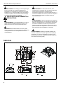
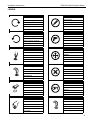
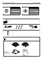
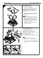
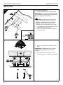
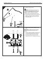
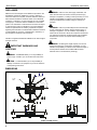
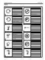
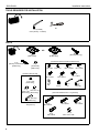
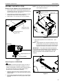
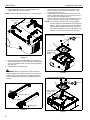
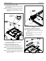
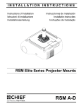
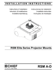
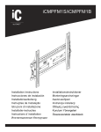
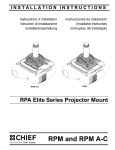
INSTALLATION INSTRUCTIONS
Instructions d´installation
Istruzioni di installazione
Installationsanleitung
RPM A-C
Instrucciones de instalación
Installatie-instructies
Instruções de Instalação
RPM
RPA Elite Series Projector Mount
RPA Elite Series Projector Mount
RPA Elite Series Projector Mount
RPA Elite Series Projector Mount
RPA Elite Series Projector Mount
RPA Elite Series Projector Mount
RPA Elite Series Projector Mount
RPM and RPM A-C
RPA Elite Series Projector Mount
Installation Instructions
DISCLAIMER
Milestone AV Technologies, and its affiliated corporations and
subsidiaries (collectively, "Milestone"), intend to make this
manual accurate and complete. However, Milestone makes no
claim that the information contained herein covers all details,
conditions or variations, nor does it provide for every possible
contingency in connection with the installation or use of this
product. The information contained in this document is subject
to change without notice or obligation of any kind. Milestone
makes no representation of warranty, expressed or implied,
regarding the information contained herein. Milestone assumes
no responsibility for accuracy, completeness or sufficiency of
the information contained in this document.
Chief® is a registered trademark of Milestone AV Technologies.
All rights reserved.
IMPORTANT WARNINGS AND
CAUTIONS!
PRECAUCIÓN: Una not de PRECAUCIÓN llama su atención
sobre la posibilidad de dañar o destruir el equipo si no sigue
las instrucciones.
AVISO: Si no lee, comprende perfectamente y sigue todas
las instrucciones, podría causar daños graves daños
personales y materiales o anular la garantía de fábrica. El
instalador es el responsable de asegurarse de que todos los
componentes están correctamente montados e instalados
siguiendo las instrucciones indicadas.
AVISO: Si no se proporciona la resistencia estructural
adecuada para este componente, podrían provocarse graves
daños personales o materiales. El instalador es el
responsable de asegurarse de que la estructura a la que este
componente está sujeta puede soportar cinco veces el peso
combinado de todo el equipo. Refuerce la estructura según
sea necesario antes de instalar el componente.
WARNING: A WARNING alerts you to the possibility of
serious injury or death if you do not follow the instructions.
CAUTION: A CAUTION alerts you to the possibility of
damage or destruction of equipment if you do not follow the
corresponding instructions.
WARNING: Failure to read, thoroughly understand, and
follow all instructions can result in serious personal injury,
damage to equipment, or voiding of factory warranty! It is the
installer’s responsibility to make sure all components are
properly assembled and installed using the instructions
provided.
WARNING: Failure to provide adequate structural strength
for this component can result in serious personal injury or
damage to equipment! It is the installer’s responsibility to
make sure the structure to which this component is attached
can support five times the combined weight of all equipment.
Reinforce the structure as required before installing the
component.
WARNING: Exceeding the weight capacity can result in
serious personal injury or damage to equipment! It is the
installer’s responsibility to make sure the combined weight of
all components attached to the RPM does not exceed 50 lbs
(22.68 kg).
iAVISOS
y PRECAUCIONES
IMPORTANTES!
AVISO: Un AVISO llama su atención sobre la posibilidad de
sufrir lesiones de gravedad o incluso mortales si no sigue las
instrucciones.
2
AVISO: Si se excede el peso máximo, podrían causarse
graves daños personales o materiales. El instalador es
responsable de asegurarse de que el peso combinado de
todos los componentes montados en el RPM no excede
22.68 kg.
WICHTIGE WARN- und
VORSICHTSHINWEISE!
WARNUNG: Ein WARNHINWEIS macht auf mögliche
schwere oder tödliche Verletzungen aufmerksam, die bei
Nichtbefolgung der Anweisungen eintreten können.
VORSICHT: Ein VORSICHTSHINWEIS macht auf Schäden
oder mögliche Zerstörung des Geräts aufmerksam, die bei
Nichtbefolgung der Anweisungen eintreten können.
WARNUNG: Falls nicht alle Anweisungen gelesen und gut
verstanden werden, kann dies zu schweren
Körperverletzungen, Schaden an den Geräten führen und die
Werksgarantie nichtig machen! Der Monteur ist dafür
verantwortlich, dass alle Komponenten unter Einhaltung der
mitgelieferten Anweisungen korrekt zusammengebaut und
eingebaut werden.
WARNUNG: Wenn für diese Komponente keine
ausreichende bauliche Tragkraft vorhanden ist, kann dies zu
schweren Körperverletzungen oder Schäden an den Geräten
führen! Der Installateur ist dafür verantwortlich zu überprüfen,
ob die Wand, an der diese Komponente verankert wird, das
Fünffache der Gesamtlast aller befestigten Geräte sicher
tragen kann. Andernfalls muss die Wand verstärkt werden,
bevor die Komponente angebracht wird.
Installation Instructions
WARNUNG: Wenn das zulässige Gewicht überschritten
wird, kann dies zu schweren Körperverletzungen oder
Schäden an den Geräten führen! Der Monteur ist dafür
verantwortlich, dass das kombinierte Gewicht aller
Komponenten, die am Modell RPM befestigt sind, nicht mehr
als 22.68 kg beträgt.
ADVERTÊNCIAS e AVISOS
IMPORTANTES!
ADVERTÊNCIA: Os alertas de ADVERTÊNCIA avisam-no
para a possibilidade de ocorrência de graves lesões ou
morte no caso de incumprimento das instruções.
AVISO: Os alertas de AVISO avisam-no para a possibilidade
de danos ou destruição do equipamento no caso de
incumprimento das instruções.
ADVERTÊNCIA: Se não ler, compreender completamente e
seguir todas as instruções podem ocorrer graves lesões
pessoais, danos no equipamento e a garantia de fábrica
pode ser anulada! É da responsabilidade do instalador
certificar-se de que todos os componentes são
correctamente montados e instalados de acordo com as
instruções fornecidas.
ADVERTÊNCIA: Se não for proporcionado apoio estrutural
adequado a este componente podem ocorrer graves lesões
pessoais ou danos no equipamento! É da responsabilidade
do instalador certificar-se de que a estrutura à qual este
componente é ligado pode suportar cinco vezes o peso
combinado de todo o equipamento. Reforce a estrutura
conforme necessário antes de instalar o componente.
ADVERTÊNCIA: Exceder a capacidade de peso pode
resultar em graves lesões pessoais ou danos no
equipamento! É da responsabilidade do instalador certificarse de que o peso combinado de todos os componentes
ligados ao RPM não excede 22.68 kg.
AVVERTENZE e PRECAUZIONI
IMPORTANTI!
AVVERTENZA: Un'AVVERTENZA mette in guardia in merito
alla possibilità di gravi infortuni, anche letali, qualora non si
osservino le istruzioni.
ATTENZIONE: Un'ATTENZIONE indica la possibilità di gravi
danni all'attrezzatura qualora non ci si attiene alle istruzioni al
riguardo.
RPA Elite Series Projector Mount
AVVERTENZA: La mancata comprensione e ottemperanza
alle istruzioni fornite può provocare gravi lesioni personali,
danni all'apparecchiatura o annullare la garanzia fornita dal
produttore. Spetta all'installatore verificare che tutti i
componenti siano assemblati correttamente e installati
secondo le istruzioni fornite.
AVVERTENZA: Una resistenza strutturale inadeguata per
questo componente può arrecare gravi infortuni o
danneggiare l'apparecchiatura. È responsabilità
dell'installatore verificare che la struttura alla quale è fissato il
componente sostenga con sicurezza cinque volte il carico
combinato di tutta l'apparecchiatura. Rinforzare la struttura
secondo necessità prima di installare i componenti.
AVVERTENZA: Un peso superiore alla capacità nominale
può arrecare gravi infortuni o danneggiare l'apparecchiatura.
È responsabilità dell'installatore verificare che il peso totale di
tutti i componenti montati sul RPM non superi 22.68 kg
(50 lb).
BELANGRIJKE AANWIJZINGEN en
WAARSCHUWINGEN!
WAARSCHUWING: Een WAARSCHUWING vestigt uw
aandacht op de mogelijkheid van ernstig of dodelijk letsel als
u de instructies niet opvolgt.
VOORZICHTIG: De aanwijzing VOORZICHTIG vestigt uw
aandacht op de mogelijkheid van beschadiging of
onherstelbare beschadiging van de apparatuur als u de
betreffende instructies niet opvolgt.
WAARSCHUWING: Door niet alle instructies te lezen,
volledig te begrijpen en op te volgen, riskeert u ernstig
persoonlijk letsel, beschadiging van de apparatuur en het
vervallen van de fabrieksgarantie. Degene die het product
installeert is ervoor verantwoordelijk dat alle onderdelen aan
de hand van de meegeleverde handleiding op de juiste wijze
worden samengebouwd en gemonteerd.
WAARSCHUWING: Als u voor deze component
onvoldoende constructiesterkte beschikbaar stelt, riskeert u
ernstig persoonlijk letsel of beschadiging van de apparatuur!
Degene die de structuur monteert waaraan deze component
is bevestigd, is ervoor verantwoordelijk dat deze minimaal vijf
maal het gezamenlijke gewicht van alle apparatuur kan
dragen. Zonodig dient u de structuur vóór de montage van
de component te versterken.
3
RPA Elite Series Projector Mount
Installation Instructions
WAARSCHUWING: Overschrijding van het draagvermogen
kan de oorzaak zijn van ernstig persoonlijk letsel en
beschadiging van de apparatuur! Degene die het product
installeert is ervoor verantwoordelijk dat het totale gewicht
van alle componenten die aan de RPM worden bevestigd
een gewicht van 22.68 kg niet overschrijdt.
IMPORTANTS AVERTISSEMENTS et
PRÉCAUTIONS!
ADVERTISSEMENT: Un ADVERTISSEMENT vous met en
garde contre les possibilités de blessures graves ou de
danger de mort si vous ne suivez pas les instructions.
PRÉCAUTION: Une PRÉCAUTION vous met en garde
contre les possibilités d´endommagements et de destruction
de l´équipement si vous ne suivez pas les instructions
correspondantes.
ADVERTISSEMENT: Le manque de la lecture, de la
compréhension et du respect total de toutes les instructions,
peut entraîner des blessures corporelles graves,
endommager l'équipement ou annuler la garantie d'usine. Il
incombe à l'installateur de s'assurer que tous les composants
sont correctement assemblés et installés à l'aide des
instructions fournies.
ADVERTISSEMENT: L'absence de l'apport d'une résistance
structurelle appropriée pour ce composant peut entraîner des
blessures corporelles graves ou endommager l'équipement.
Il incombe à l'installateur de s'assurer que la structure à
laquelle le composant est attaché peut soutenir cinq fois le
poids combiné de tout l'équipement. Renforcer la structure
selon les besoins avant l'installation du composant.
ADVERTISSEMENT: Dépasser la capacité pondérale peut
entraîner des blessures corporelles graves ou endommager
l'équipement. Il incombe à l'installateur de s'assurer que le
poids combiné de tous les composants attachés à RPM n'est
pas supérieur à 22.68 kg (50 lb).
DIMENSIONS
165
6.50
21
.84
140
5.50
114
4.50
43
1.69
21
.84
57
2.25
43
1.69
1.50" DIA NPT
70
2.75
140
5.50
YAW ADJUSTMENT
POINT 20
22
.88
136
5.36
7
.28
117
4.61
69
2.72
ROLL ADJUSTMENT
POINT 3
4
PITCH ADJUSTMENT
POINT 20
Installation Instructions
RPA Elite Series Projector Mount
LEGEND
Tighten Fastener
Pencil Mark
Serrez les fixations
Marquage au crayon
Serrare il fissaggio
Segno a matita
Befestigungsteil festziehen
Stiftmarkierung
Apretar elemento de fijación
Marcar con lápiz
Bevestiging vastdraaien
Potloodmerkteken
Apertar fixador
Marcar com lápis
Loosen Fastener
Drill Hole
Desserrez les fixations
Percez un trou
Allentare il fissaggio
Praticare un foro
Befestigungsteil lösen
Bohrloch
Aflojar elemento de fijación
Perforar
Bevestiging losdraaien
Gat boren
Desapertar fixador
Fazer furo
Phillips Screwdriver
Adjust
Tournevis à pointe cruciforme
Ajuster
Cacciavite a stella
Regolare
Kreuzschlitzschraubendreher
Einstellen
Destornillador Phillips
Ajustar
Kruiskopschroevendraaier
Afstellen
Chave de fendas Phillips
Ajustar
Hex-Head Wrench
Remove
Clé à tête hexagonale
Retirez
Chiave esagonale
Rimuovere
Sechskantschlüssel
Entfernen
Llave de cabeza hexagonal
Quitar
Zeskantsleutel
Verwijderen
Chave de cabeça sextavada
Remover
Open-Ended Wrench
Optional
Clé à fourche
En option
Chiave a punte aperte
Opzionale
Gabelschlüssel
Optional
Llave de boca
Opcional
Steeksleutel
Optie
Chave de bocas
Opcional
By Hand
Security Wrench
À la main
Clé de sécurité
A mano
Chiave di sicurezza
Von Hand
Sicherheitsschlüssel
A mano
Llave de seguridad
Met de hand
Veiligheidssleutel
Com a mão
Chave de segurança
5
RPA Elite Series Projector Mount
Installation Instructions
Hammer
Target of Projector
Martillo
Punto de enfoque del proyector
Hammer
Ziel des Projektors
Martelo
Mira do projector
Martello
Punto di proiezione
Hamer
Doel van de projector
Marteau
Cible du projecteur
1/4"
A (1)
A (1)
or
B (1)
Example Only
(Interface bracket
varies dependent
on projector model)
6
7/32" (6mm) dia.
Installation Instructions
RPA Elite Series Projector Mount
1
RPM INSTALLATION
Threaded Pipe Installation
1.
Carefully determine required mounting location.
IMPORTANT ! : This will require knowing the
lens to screen distance. See projector
specifications for details on determining this
distance.
2
2.
4
Install ceiling plate and extension accessories
following installation instruction provided by
manufacturer.
WARNING: IMPROPER INSTALLATION CAN
3
RESULT IN SERIOUS PERSONAL INJURY OR
DAMAGE TO EQUIPMENT! Structural members
MUST be capable of supporting five times the
combined weight of all equipment being mounted.
3.
Align RPM with end of NTP pipe.
4.
Thread RPM up onto pipe by turning counterclockwise until hand tight.
(A)
2
Rough Alignment of RPM
1.
Turn RPM clockwise or counter-clockwise until
front of mount is facing target.
IMPORTANT ! : When RPM is properly
positioned, the set screw access hole should be
pointing directly at target.
(see bottom detail in figure at left)
1
2.
(A)
Secure RPM to pipe by turning set screw until tight.
CAUTION: DO NOT OVERTIGHTEN!
Overtightening of setscrew can damage threads on
pipe.
3
3.
Turn security screw using a Phillips screwdriver
until set screw cannot be seen through access hole
in RPM.
1
7
RPA Elite Series Projector Mount
Installation Instructions
INSTALLATION
Wood Stud Installation
1a
1.
Carefully determine required mounting location.
IMPORTANT ! : This will require knowing the lens
to screen distance. See projector specifications for
details on determining this distance.
1
WARNING: IMPROPER INSTALLATION CAN
RESULT IN SERIOUS PERSONAL INJURY OR
DAMAGE TO EQUIPMENT! Structural members
MUST be capable of supporting five times the
combined weight of all equipment being mounted.
2.
Using the RPM as a guide, mark four mounting hole
locations with a pencil or similar tool.
3.
Drill four 1/8" (3mm) dia. pilot holes to a depth of
1-3/4" (45mm) deep.
4.
Align four mounting holes in RPM with four pilot
holes.
X4
2
Ø 3mm
(Ø 1/8”)
X4
45mm
(1-3/4”)
3
IMPORTANT ! : Make sure mount is properly
oriented towards target before securing to
structure.
5.
4
(A)
x4
5
8
Secure RPM to structure using four 1/4" flat
washers and four 1/4" x 3" lag bolts (not included).
Installation Instructions
RPA Elite Series Projector Mount
Concrete Installation
1b
1.
Determine mounting location.
WARNING: IMPROPER INSTALLATION CAN
RESULT IN SERIOUS PERSONAL INJURY OR
DAMAGE TO EQUIPMENT! Structural members
MUST be capable of supporting five times the
combined weight of all equipment being mounted.
1
2.
Using the RPM as a guide, mark four mounting hole
locations on ceiling using a pencil or similar tool.
3.
Drill four 3/8" (10mm) dia. pilot holes to a depth of
2-1/2" (64mm) deep.
4.
Align four mounting holes in RPM with four pilot
holes.
X4
2
Ø 10mm
(Ø 3/8”)
X4
3
64mm
(2-1/2”)
IMPORTANT ! : Make sure mount is properly
oriented towards target before securing to
structure.
X (4)
5
5.
Install four Toggler A10 Alligator concrete anchors
(not included) by inserting into pilot holes and
pounding in until flush with mounting surface.
6.
Secure RPM to structure using four 1/4" flat
washers and four 1/4" x 3" lag bolts. (not included)
(A)
X4
6
9
INSTALLATION INSTRUCTIONS
Instrucciones de instalación
Installationsanleitung
Instruções de Instalação
SLBU
Istruzioni di installazione
Installatie-instructies
Instructions d´installation
SLMU
Universal Interface Brackets
Spanish Product Description
German Product Description
Portuguese Product Description
Italian Product Description
Dutch Product Description
French Product Description
SLBU/SLMU
SLBU/SLMU
Installation Instructions
DISCLAIMER
Milestone AV Technologies and its affiliated corporations and
subsidiaries (collectively "Milestone"), intend to make this
manual accurate and complete. However, Milestone makes no
claim that the information contained herein covers all details,
conditions or variations, nor does it provide for every possible
contingency in connection with the installation or use of this
product. The information contained in this document is subject
to change without notice or obligation of any kind. Milestone
makes no representation of warranty, expressed or implied,
regarding the information contained herein. Milestone assumes
no responsibility for accuracy, completeness or sufficiency of
the information contained in this document.
Chief® is a registered trademark of Milestone AV Technologies.
All rights reserved.
WARNING: Failure to read, thoroughly understand, and
follow all instructions can result in serious personal injury,
damage to equipment, or voiding of factory warranty! It is the
installer’s responsibility to make sure all components are
properly assembled and installed using the instructions
provided.
WARNING: Failure to provide adequate structural strength
for this component can result in serious personal injury or
damage to equipment! It is the installer’s responsibility to
make sure the structure to which this component is attached
can support five times the combined weight of all equipment.
Reinforce the structure as required before installing the
component.
WARNING: Exceeding the weight capacity can result in
serious personal injury or damage to equipment! It is the
installer’s responsibility to make sure the combined weight of
all components attached to the SLBU-SLMU interface
brackets does not exceed 50 lbs (22.68 kg).
IMPORTANT WARNINGS AND
CAUTIONS!
WARNING: A WARNING alerts you to the possibility of
serious injury or death if you do not follow the instructions.
CAUTION: A CAUTION alerts you to the possibility of
damage or destruction of equipment if you do not follow the
corresponding instructions.
DIMENSIONS
95.2
Ø 3.75
BOLT CIRCLE
1 1/2"
NPT
4X 7.5°
4X 32.5°
6.7
4X Ø .27
190.2
R7.49
26.97
1.06
169.07
143.7
6.66
5.66
119
82.6
4.69
3.25
88.6
93
3.49
3.66
(SLBU with RMA shown)
2
Installation Instructions
SLBU/SLMU
LEGEND
Tighten Fastener
Pencil Mark
Apretar elemento de fijación
Marcar con lápiz
Befestigungsteil festziehen
Stiftmarkierung
Apertar fixador
Marcar com lápis
Serrare il fissaggio
Segno a matita
Bevestiging vastdraaien
Potloodmerkteken
Serrez les fixations
Marquage au crayon
Loosen Fastener
Drill Hole
Aflojar elemento de fijación
Perforar
Befestigungsteil lösen
Bohrloch
Desapertar fixador
Fazer furo
Allentare il fissaggio
Praticare un foro
Bevestiging losdraaien
Gat boren
Desserrez les fixations
Percez un trou
Phillips Screwdriver
Socket Wrench
Destornillador Phillips
Llave de cubo
Kreuzschlitzschraubendreher
Llave de cubo
Chave de fendas Phillips
Chave de caixa
Cacciavite a stella
Chiave a brugola
Kruiskopschroevendraaier
Dopsleutel
Tournevis à pointe cruciforme
Clé à douilles
Open-Ended Wrench
Remove
Llave de boca
Quitar
Gabelschlüssel
Entfernen
Chave de bocas
Remover
Chiave a punte aperte
Rimuovere
Steeksleutel
Verwijderen
Clé à fourche
Retirez
By Hand
Optional
A mano
Opcional
Von Hand
Optional
Com a mão
Opcional
A mano
Opzionale
Met de hand
Optie
À la main
En option
Hex-Head Wrench
Security Wrench
Llave de cabeza hexagonal
Llave de seguridad
Sechskantschlüssel
Sicherheitsschlüssel
Chave de cabeça sextavada
Chave de segurança
Chiave esagonale
Chiave di sicurezza
Zeskantsleutel
Veiligheidssleutel
Clé à tête hexagonale
Clé de sécurité
3
SLBU/SLMU
Installation Instructions
TOOLS REQUIRED FOR INSTALLATION
#2
1/4" (included)
5/32" (security - included)
PARTS
OR
A (1)
[SLBU Plate]
C (2)
[Security Cover Bracket]
[SLBU Only]
B (4)
[SLBU/SLMU Leg]
A (1)
[SLMU Plate]
[Universal Projector Interface Hardware Kit]
D (4)
[Thumb Nut]
[SLBU Only]
K (4)
8-32 x 3/8"
L (4)
8-32 x 1/4"
M (4)
M2.5 x 10mm
[All Points Security Kit]
P (4)
M4 x 10mm
E (2)
10-24 x 3/8"
[SLBU Only]
S (4)
M4
H (1)
G (4)
10-24 x 3/8" 5/16-18 x 1/2"
[SLBU Only] [SLBU Only]
R (4)
M6 x 12mm
Q (4)
M5 x 12mm
T (4)
1/4-20
N (4)
M3 x 10mm
U (1)
1/4"
V (1)
5/32"
(security)
[Universal Hardware Kit - Long Screws]
J (1)
5/32" (security)
[SLBU Only]
[No hardware
designated "F"]
W (4)
M3 x 25mm
Z (4)
M6 x 25mm
4
X (4)
M4 x 25mm
AA (4)
.500 x .257 x .625
Y (4)
M5 x 25mm
Installation Instructions
SLBU/SLMU
ASSEMBLY AND INSTALLATION
NOTE: Only use washers (S) if using M or N screws to attach
screw adapters to projector.
Remove Screw Adapters from SLBU/SLMU Legs
1.
Press locking buttons on SLBU/SLMU leg (B) firmly and
simultaneously push clip cover toward enclosed sliding stud
mount bracket and screw. (See Figure 1)
2.
Screw adapter and attached height-adjustment nut will be
released. Set aside for later use. (See Figure 1)
3.
Repeat Steps 1-2 for each leg to be used in installation.
2
(M, N, P, Q or R)
(S) x 3 or 4
(with M or N only)
(B)
1
sliding stud mount
bracket and screw
locking button x 2
clip cover
screw adapters
with nuts
Figure 2
3.
Adjust height-adjustment nuts to desired level.
Figure 3)
(See
NOTE: Height-adjustment nuts should be adjusted as low as
(side view)
possible while ensuring that the legs will always clear
any elevated surfaces on the projector. All nuts must be
adjusted to the same level to ensure an even mount.
IMPORTANT ! : The optional Universal Hardware Kit Long Screws (see Parts drawing) may be used if there is
interference with any part of the projector, and more
height is required to clear elevated surfaces of the
projector.
height-adjustment nut
2
screw adapter
Figure 1
3
Attach Projector to SLBU/SLMU
WARNING: Exceeding the weight capacity can result in
serious personal injury or damage to equipment! It is the
installer’s responsibility to make sure the combined weight of
all components attached to the SLBU-SLMU interface
brackets does not exceed 50 lbs (22.68 kg).
1.
2.
Determine proper size screw to insert into projector. Test
Phillips screws (M, N, P, Q and R) provided until one fits the
projector holes.
fully lowered
Figure 3
Insert screws through M4 flat washers (S), screw adapters
with height-adjustable nuts and into projector holes. (See
Figure 2)
5
SLBU/SLMU
4.
Installation Instructions
Place SLBU/SLMU legs (B) over screw adapters and
height-adjustment nuts. (See Figure 4)
NOTE: Make sure arm latch clips are in the unlocked position.
(B) x 3 or 4
7.
Manuever legs so that sliding stud mount brackets and
screws are towards the middle of the projector. (See
Figure 6) and (See Figure 7)
8. Position sliding stud mount brackets and screws so that
SLBU or SLMU main plate (A) can be evenly mounted to
legs. (See Figure 6) and (See Figure 7)
9. Use 1/4" hex key (U) to secure Allen nuts (T) to screws on
sliding stud mounts. (See Figure 6) and (See Figure 7)
NOTE: The following examples are two of many possible
scenarios based on typical examples of mounting hole
patterns. Specific connection points will vary based on
the hole pattern. Multiple scenarios may be used for
each specific hole pattern as long as the weight of the
projector is centered and balanced after mounting.
Three-hole scenario example
(T) x 3
9
(A)
sliding stud mount
brackets and
screws
Figure 4
5.
Press locking buttons on SLBU/SLMU leg (B) firmly and
simultaneously push clip cover away from enclosed sliding
stud mount bracket until clip cover is in the locked position.
(See Figure 5)
6.
Repeat Step 5 for remaining legs.
WARNING: Make sure legs have securely locked onto
height-adjustable nuts with the latch clips. If the legs are not
properly locked onto the adapters, the projector could fall
from the SLBU/SLMU mount causing SERIOUS INJURY or
DEATH!
Figure 6
Four-hole scenario example
(A)
5
locking buttons
9
sliding stud mount
brackets and
screws
open position
locked position
Figure 5
Figure 7
6
(T) x 4
Installation Instructions
SLBU/SLMU
Attach SLBU/SLMU to RPA or RPM
1.
On SLBU, partially install four thumb nuts (D) to SLBU main
plate screws. Be sure to install thumb nuts with tapered side
down. (See Figure 8)
NOTE: If using optional security brackets (C) to connect SLBU
bracket to RPA or non-locking RPM mount, refer to
Security Bracket Installation section prior to installing
thumb nuts.
(B)
1
(K)
Install thumb nuts
with tapered
side down
1
(D) x 4
security hole
Figure 9
Security Bracket Installation (Optional)
(A)
NOTE: Security brackets (C) can only be used when
connecting SLBU bracket to RPA or non-locking RPM
mounts.
1.
Install security brackets (C) over screws on SLBU main
plate. (See Figure 10)
2.
Partially install thumb nuts (D) onto SLBU main plate
screws. (See Figure 10)
(D) x 4
2
(C) x 2
Figure 8
2.
Attach SLBU/SLMU to RPA/RPM. Refer to RPA/RPM
installation manual for details.
Security Screw Installation (Optional)
1.
Install #8-32 x 3/8" button head security screws (K) into
security holes on SLBU/SLMU legs. (See Figure 9)
NOTE: Up to two security screws can be installed on each leg.
It is recommended that screws be installed in holes that
are difficult to access to achieve maximum security.
NOTE: Cable ties (not included) may be used instead of the
security screws. Thread cable tie through both holes on
leg and secure cable tie.
Figure 10
7
SLBU/SLMU
Installation Instructions
USA/International
Europe
Chief Manufacturing, a products division
of Milestone AV Technologies
8802-002058 Rev00
2010 Milestone AV Technologies, a
Duchossois Group Company
www.chiefmfg.com
04/10
Asia Pacific
A
P
F
A
P
F
A
8401 Eagle Creek Parkway, Savage, MN 55378
800.582.6480 / 952.894.6280
877.894.6918 / 952.894.6918
Fellenoord 130 5611 ZB EINDHOVEN, The Netherlands
+31 (0)40 2668620
+31 (0)40 2668615
Office No. 1 on 12/F, Shatin Galleria
18-24 Shan Mei Street
Fotan, Shatin, Hong Kong
P 852 2145 4099
F 852 2145 4477