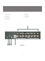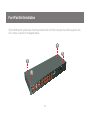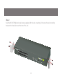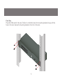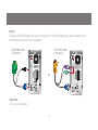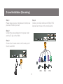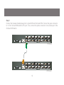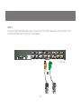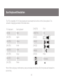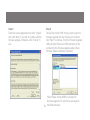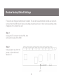
1
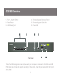
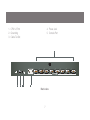
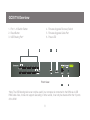
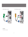
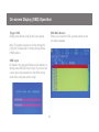
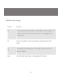
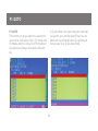
Installation Guide 8/16-Port USB PS/2 Combo KVMP Switch 1 GCS1808/GCS1716 PART NO. M1102/M1074 ©2009 IOGEAR. All Rights Reserved. Part No. M1102/M1074 IOGEAR, the IOGEAR logo, MiniView®, VSE are trademarks or registered trademarks of IOGEAR, Inc. Microsoft and Windows are registered trademarks of Microsoft Corporation. IBM is a registered trademark of International Business Machines, Inc. Macintosh, G3/G4 and iMac are registered trademarks of Apple Computer, Inc. IOGEAR makes no warranty of any kind with regards to the information presented in this document. All information furnished here is for informational purposes only and is subject to change without notice. IOGEAR, Inc. assumes no responsibility for any inaccuracies or errors that may appear in this document. 2 Package Contents –– –– –– –– –– –– –– –– –– –– –– –– 1 x 8/16-Port USB PS/2 Combo KVMP Switch 1 x PS/2 KVM Cable 1 x USB KVM Cable 1 x Console Cable 1 x Cascade Cable 1 x Firmware Upgrade Cable 1 x Rack Mount Kit (1 Set) 1 x Grounding Wire 1 x Foot Pad Set (4 Pads) 1 x Power Adapter 1 x Installation Guide 1 x Warranty Card 3 System Requirements Console • A display with an VGA (HDB-15) input • A USB or PS/2 Keyboard and Mouse Computers • A video output with an VGA (HDB-15) female connector • Open USB port or PS/2 keyboard and mouse ports 4 Table of Contents Package Contents 3 Hotkey Setting Mode (HSM) 50 System Requirements 4 Mac Keyboard Emulation 52 GCS1808 Overview 6 Sun Keyboard Emulation 53 GCS1716 Overview 8 Factory Default Settings 54 Foot Pad Set Installation 10 Firmware Upgrade 55 Rack Mounting 11 Upgrade Fail 59 Grounding 14 Restore Factory Default Settings 60 Single Level Installation 15 2-Level Installation (Cascading) 18 Federal Communications Commission (FCC) Statement 62 CE Statement 64 Limited Warranty 65 Contact 66 LED Indication 22 Port Switching 23 On-screen Display (OSD) Operation 24 5 GCS1808 Overview 1. Port 1~8 switch Button 2. Reset Button 3. USB Sharing Port* 4. Firmware Upgrade Recovery Switch 5. Firmware Upgrade Cable Port 6. Power LED 1 2 3 Front view 4 5 6 *Note: The USB sharing device can only be used if your computer is connected to the KVM via a USB KVM Cable. Also, it does not support cascading; in other words, it can only be shared within the 8 ports of the KVM. 6 4. Power Jack 5. Console Port 1. CPU1~8 Port 2. Grounding 3. Cable Tie Slot 1 8 7 6 CONSOLE 2 3 4 5 4 PS/2-USB 5 Back view 7 3 CPU 2 1 GCS1716 Overview 1. Port 1~16 Switch Button 2. Reset Button 3. USB Sharing Port* 4. Firmware Upgrade Recovery Switch 5. Firmware Upgrade Cable Port 6. Power LED 1 2 3 Front view 4 5 6 *Note: The USB sharing device can only be used if your computer is connected to the KVM via a USB KVM Cable. Also, it does not support cascading; in other words, it can only be shared within the 16 ports of the KVM 8 1. CPU1~16 Port 2. Grounding 3. Cable Tie Slot 4. Power Jack 5. Console Port 1 18 17 16 15 14 13 12 11 8 7 6 5 4 3 2 1 CONSOLE 2 3 4 5 PS/2-USB Back view 9 CPU Foot Pad Set Installation Flip the KVM switch upside down. Peel the protective films off of the foot pads, then stick the pads to the four corners, as shown in the diagram below. 10 Rack Mounting Step 1 Remove the screws from the left and right sides of the switch (2 screws total) near the front of the switch. 11 Step 2 Use the M3 x 8 Phillips hex head screws supplied with the rack mounting kit to screw the rack mounting brackets into the sides near the front of the unit. 12 Final Step Place the KVM switch in the rack. Position it so that the holes in the mounting brackets line up with the holes in the rack. Secure the mounting brackets to the front of the rack. 13 Grounding To prevent damaging your equipment, it is important that all devices are properly grounded. Use the included grounding wire to ground the KVM switch by connecting one end of the wire to the grounding terminal, and the other end of the wire to a suitable grounded object. 18 17 16 15 14 13 12 11 8 7 6 5 4 3 2 1 CONSOLE PS/2-USB 14 CPU Single Level Installation Step 1 Please make sure your computers and monitor are powered off before you start. Step3 Connect the Console cable to the Console port of the KVM. Step 2 Connect the power adapter to the power outlet and the DC jack of the KVM. 18 17 16 15 14 13 12 11 8 7 6 5 4 3 2 1 CONSOLE 2 PS/2-USB 3 15 CPU Step 4 Connect your VGA monitor and USB or PS/2 keyboard and mouse to the console Cable. 18 17 16 15 14 13 12 11 8 7 6 5 4 3 2 1 CONSOLE PS/2-USB 5 4 USB VGA PS/2 16 CPU Step 5 Connect a USB KVM Cable (with a green connector) or PS/2 KVM Cable (with a yellow connector) from the KVM switch to each of your computers. USB KVM Cable Connection PS/2 KVM Cable Connection or Final Step Turn on your computers. 17 2-Level Installation (Cascading) Step 1 Please make sure your computers and monitor are powered off before you start. Step 4 Connect your VGA monitor and USB or PS/2 keyboard and mouse to the console Cable Step 2 Connect the power adapters to the power outlet and the DC jack of the KVMs. 17 16 15 8 7 6 5 CONSOLE Step 3 Connect the Console cable to the Console port of the 1st level KVM. 18 17 16 15 14 13 12 11 8 7 6 5 4 3 2 1 CONSOLE 2 18 PS/2-USB 5 CPU USB 18 VGA 4 PS/2-USB 4 3 14 PS/2 CPU Step 5 Connect the Cascade Cable between the 1st level KVM and 2nd level KVM. Connect the green connector to 1 of the 1st level KVM switch’s CPU port. Then, connect the yellow connector to the console port of the 2nd level KVM switch. 18 17 16 15 14 13 12 11 8 7 6 5 4 3 2 1 CONSOLE CPU PS/2-USB 1st Level 18 17 16 15 14 13 12 11 8 7 6 5 4 3 2 1 CONSOLE PS/2-USB CPU 2nd Level 19 Step 6 Connect a USB KVM Cable (with a green connector) or PS/2 KVM Cable (with a yellow connector) from the 2nd level KVM switch to each of your computers. 18 17 16 15 14 13 12 11 8 7 6 5 4 3 2 1 CONSOLE PS/2-USB CPU 2nd Level 6 20 USB KVM Cable Connection PS/2 KVM Cable Connection or Final Step Turn on your computers. 21 LED Indication LED Description No LED No computer is connected to the specific port or the computer is connected to the specific port but it is not powered on Orange The specific port has a computer connected and it is powered on, but does not focus on the KVM Green The specific port has focus on the KVM 22 Port Switching Port Switching via Front Panel Switch Button Simply press the specific push button to switch the focus to the specific port Port Switching via On-Screen DIsplay (OSD) Please refer to OSD Operation section. Port Switching via Hotkey Please refer to Hotkey Setting Mode (HSM) section. 23 On-screen Display (OSD) Operation Trigger OSD Simply press [Scroll Lock] [Scroll Lock] rapidly. OSD Main Screen When you invoke the OSD, a screen similar to the one below appears: Note: This hotkey sequence can be changed to [Ctrl] [Ctrl]. Please refer to Hotkey Setting Mode (HSM) section. OSD Login By default, the Login and Password are blanks, so simply press [Enter] [Enter] to login. If you have set a user name and password on the KVM, simply enter them and press enter to login. 24 Notes: 1. The diagram depicts the administrator’s main screen. The user main screen does not show the F4 and F6 functions, since these are reserved for the administrator and can’t be accessed by users. 2. The OSD always starts in list view, with the highlight bar at the same position it was in the last time it was closed. 3. Only the ports that have been set accessible by the administrator for the current logged in user are visible. 4. If there is a next to the monitor icon, which means that port is attached to another KVM (Cascading). Click on a switch number, or move the highlight bar to it then press the right arrow key to expand the list. Similarly, to collapse a switch’s port list, click on the switch number, or move the highlight bar to it then press the left arrow key to collapse the list. 25 OSD Main Screen Headings Heading Description PN This column lists the port ID numbers for all the KVM ports on the installation. The simplest method to access a particular computer is move the highlight bar to it then press Enter. QV QV If a port is selected for quick view scanning an arrowhead shows in this column. ☼ The computers that are powered on and are online will a sun symbol in this column to indicate so Name If a port has been given a name, its name appears in this column. 26 OSD Navigation • To dismiss the menu, and deactivate OSD, click the X in the upper right corner of the OSD window; or press [Esc]. • To log out, click F8 at the top of the main screen, or press [F8]. • To move up or down through the list one line at a time, click the up and down triangle symbols () or use the up and down arrow keys on the keyboard. If there are more list entries than what appears on the main screen, the screen will scroll down. • To move up or down through the list one screen at a time, click the up and down arrow symbols (), or use the [PgUp] and [PgDn] keys. If there are more list entries than what appears on the main screen, the screen will scroll. • To activate a port, double-click it, or move the highlight bar to it then press [Enter]. • After executing any action, you automatically go back to the menu one level above. OSD Function There are eight options showing on top of the OSD screen. Simply click the function key on the top of the screen or press the specific function key on the keyboard on access the specific function. 27 F1: GOTO F1: GOTO This function is to let you switch to a specific port via port ID or port’s name. Enter [1] to choose from Port Name and [2] to choose from Port Number in the yellow box locating in the bottom of the pink bar. If [1] was chosen, then type in the port’s name that you want to go to and then press [Enter]. You can also move the red highlight bar to the specific port that you want to go to and press [Enter]. 28 F2: LIST If [2] was chosen then you can go to a specific port by entering the port ID. You can also move the red highlight bar to the specific port that you want to go to and press [Enter]. F2: LIST This function allows you to choose a way that you wish to list the ports in the OSD display on the main screen. Simply move the red highlight bar to the option that you wish to choose and press [Enter]. You will see the hand symbol will be pointing at the option that you chose, then simply press [Esc] to exit the function. 29 Function Description All List out all ports that the administrator has set as accessible for the current logged in user Quick View List out only the ports that have been set as quick view ports Powered ON List out only the ports that have been powered on Quick View + Powered ON List out only the ports that have been set as quick view ports and they have been powered on 30 F3: SET OSD Hotkey This function allows you to switch the way to trigger the hotkey between [Scroll Lock] [Scroll Lock] and [Ctrl] [Ctrl]. Simply move the red highlight bar to the hotkey setting that you would like to choose and press [Enter]. Then press [Esc] to exit from this function. F3: SET There are 10 different settings within the SET section, which they are as follow: OSD Hotkey Port ID Display Position Port ID Display Duration Port ID Display Mode Scan Duration Scan-Skip Mode Screen Blanker Hotkey Command Mode Hotkey OSD Language 31 Port ID Display Duration This function allows you to change the port ID display duration between 3 seconds and off. Simply move the red highlight bar to the option that you would like to choose and press [Enter]. Then, press [Esc] to exit this function. Port ID Display Position This function allows you to change the position of the port ID that’s showing on the screen as the image below. Simply change the position by using the up, down, left and right arrows to adjust to the place that you want the port ID to show in the future and press [Enter]. 32 Scan Duration This function allows you to set the autoscan time interval between 0 second to 255 seconds (5 second is set by default). Simply enter the number between 0-225 and press [Enter]. Port ID Display Mode This function allow you to choose the way you want to show the ports in the OSD main screen – port number only, port name only or both. Simply move the red highlight bar to the option that you like to use and press [Enter]. Then, press [Esc] to exit from this function. 33 Scan-Skip Mode This function allows you to set the behavior in autoscan mode. Simply move the red highlight bar to the behavior you want and press [Enter]. Then, press [Esc] to exit from this function. Function Description All Scan all ports that the administrator has set as accessible for the current logged in user Quick View Scan only the ports that have been set as quick view ports (This option will only show up for administrator account) Powered ON Scan only the ports that have been powered on Quick View + Powered ON Scan only the ports that have been set as quick view ports and they have been powered on 34 Screen Blanker This function allows you to set the time interval to have the KVM goes to a black screen. Simply enter the number between 0 to 30 and press [Enter]; then, press [Esc] to exit from this function. Hotkey Command Mode This function allows you to enable or disable the hotkey commands. Simply press Y for yes and N for no. Then, press [Esc] to exit from this function. 35 OSD Language This function allows you to choose the OSD language between English, Deutsch, Japanese, Simplified Chinese and Traditional Chinese. Simply move the red high light bar to the language that youwish to choose and press [Enter]. Then, press [Esc] to exit from this function. Hotkey This function allows you to set the hotkey sequence that you wish to use to trigger hotkeys commands. Simply move the red high light bar to choose the sequence that you wish to use and press [Enter]. Then, press [Esc] to exit from this function. 36 F4: ADM F4: ADM This function will only be shown if you have login as Administrator. There are 11 different functions within the ADM section, which they are as follow: Set User Login This function allows you to setup the login name and password for the users accounts. There are 5 user accounts in the system – Administrator, User1, User2, User3 and User4. Move the red high light bar to the user account that you wish to setup and press [Enter]. Set User Login Set Accessible Ports Set Logout Timeout Edit Port Names Restore Default Values Clear The Name List Activate Beeper Set Quick View Ports Set Operating System Firmware Upgrade Keyboard Language Keyboard Language 37 Once the user name and password are set correctly, you will see the message in the bottom of the screen indicating the setup is ok. Then simply press [Esc] to exit from the function. Then simply type in the user name and password. Then, enter the password again for confirmation then press [Enter]. (We have used the administrator account as an example.) 38 Set Accessible Ports This function allows you to setup the access on each port for each user. Use [Spacebar] to cycle through all the entries and press [Enter] to complete the setup. Then, press [Esc] to exit from the function. Function Description F (Full) User has full access on the specific port V (View) User can only view the port with no access for the specific port (Blank) User cannot view nor access for the specific port 39 Set Logout Timeout This function allows you to set a time that the KVM will automatically logout after being idle for a certain period of time. Move the red highlight bar to this function and press [Enter]. Then enter a number from 0-180 (in terms of minutes) as the time interval and press [Enter]. Edit Port Names This function allows you to customize a name on each port of the KVM. Simply move the red highlight bar to the port that you wish to customize a name and press [Enter]. 40 Restore Default Values This function allows you to restore all settings into factory default settings. Move the red highlight bar to Restore Default Values and press [Enter]. Then type Y to proceed restoring or N to cancel the restore. Enter the port name that you wish to show in OSD for that specific port and press [Enter] to complete the editing. Then, press [Esc] to exit from this function. 41 Activate Beeper This function allows you to enable or disable the beeper sound while switching port. Move the red highlight bar to Activate Beeper and press [Enter]. Then type Y to activate or N to deactivate. Clear The Name List This function allows you to clear up all the port names to blanks. Move the red highlight bar to Clear The Name List and press [Enter]. Then type Y to proceed clearing or N to keep the name list. 42 Set Quick View Ports This function allows you to set the desire ports as Quick View Ports. If a port is selected as a Quick View Port, an icon will show in the QV column of the OSD main screen. Simply more the red highlight bar to the desire port and press [Spacebar] to select the port as a Quick View Port. 43 Set Operating System This function allows you to define what kind of operating system is being used in each port. Simply move the red highlight bar to the desire port and press [Spacebar] to cycle through the options between WIN, MAC, SUN or OTHER. Note: The keyboard Operating platform will changed accordingly depending what you have chosen in this function. For example, if you have chosen Mac in Port 1 as the image is shown, the keyboard will change Mac keyboard emulation mode. Please see Hotkey Setting Mode (HSM) and Mac/Sun Keyboard Emulation sections to see the details. 44 Firmware Upgrade This function allows you to have the KVM activates the firmware upgrade mode so that you can perform a firmware upgrade to the KVM. If you would like to do a firmware upgrade, connect the firmware cable between the computer and KVM, then type Y to proceed with the firmware upgrade; otherwise, type N to cancel. After you type Y, you will see the below screen. The KVM is now in firmware upgrade mode. Please see Firmware Upgrade section for details about how to perform a firmware upgrade. 45 Keyboard Language This function allows you to choose the keyboard language of your console keyboard. Auto is chosen by default; if you want to change the language, simply move the red highlight bar to the desire keyboard language that you wish to change to and then press [Enter]. 46 F5: SKP F5: SKP This function allows you to trigger Skip Mode. Simply press [F5] to activate skip mode. When you see a left and right arrow next to the port number as the image below, you can press the arrow keys to skip to different ports. (Skip Mode’s behavior depends on the setup that you chose in Scan-Skip Mode, please to F3 – SET for more detail about Scan-Skip Mode) Function Description [←] Switch to the last accessible port [→] Switch to the next accessible port [↑] Switch to the last accessible port* Note: If you have cascaded your KVM, it will switch to the last accessible port from level 2 of the last port from level 1. [↓] Switch to the next accessible port* Note: If you have cascaded your KVM, it will switch to the next accessible port from level 2 of the next port from level 1. 47 F6: BRC / F7: SCAN F6: BRC This function will only be shown if you have login as Administrator. Simply press [F6] to trigger Broadcast (BRC) Mode, then you will see a speaker symbol next to the port number. When BRC is activated, your command that you send from the console will be sent to all available computers – the computers that are listed in the OSD main screen, please go to F2 – LIST section for details. During BRC Mode, console mouse will not function normally. Simply press [F6] again to turn BRC Mode off. F7: SCAN This function allows you to autoscan all the available ports. (This autoscan behavior depends on the Scan-Skip Mode and Scan Duration.) Please go to F3 – SET section for details. Simply press [F7] to trigger Autoscan Mode, then you will see a [S] next to the port ID number on the screen. When the Autoscan Mode is activated, the console will not function normally until you exit from Autoscan Mode. During Autoscan Mode, you can press [P] or left-click on your mouse once to pause at a specific port. When you are done pausing, simply press any key from the keyboard or left-click once on your mouse to resume. When you are done auto-scanning, simply press [Spacebar] or [Esc] to exit from Autoscan Mode. 48 F8: LOUT You can also trigger the autoscan by front panel pushbutton or hotkey command. Press and hold Port 7 and Port 8 pushbutton on the GCS1808 (Port 15 and Port 16 for GCS1716) to trigger autoscan with default autoscan time interval. For hotkey command, please refer to Hotkey Setting Mode (HSM) section. F8: LOUT This function allows you to logout of the OSD. So, when another person is trying to access this from the console, he would have to login again. Simply Press Y to proceed the logout and N to cancel. 49 Hotkey Setting Mode (HSM) Function Description 1. Press and hold [Num Lock] 2. Press and release [-] 3. Release [Num Lock] Invoking hotkey setting mode Invoke HSM, then press [h] Change the HSM invocation keys from [Num Lock] to [Ctrl] and from [-] to [F12] Invoke HSM, then press [t] Switch port switching hotkey sequence between [Scroll Lock] [Scroll Lock] and [Ctrl] [Ctrl] Invoke HSM, then press [F1] Set keyboard operating platform to PC compatible Invoke HSM, then press [F2] Set keyboard operating platform to Mac compatible Invoke HSM, then press [F3] Set keyboard operating platform to Sun compatible Invoke HSM, then press [F5] Perform keyboard / Mouse reset on the port that has KVM focus. Note: To exit HSM manually, press Esc or spacebar. Note: You can also press and hold Port 1 and Port 2 front panel push button to perform keyboard / mouse reset. 50 Invoke HSM, then press [←] Invokes Skip mode and skips from the current port to the first accessible port previous to it Invoke HSM, then press [→] Invokes Skip mode and skips from the current port to the next accessible port Invoke HSM, then press [b] Toggle hotkey beepers on or off Invoke HSM, then press [X*] [Y*] [Enter] Switches KVM focus to the computer that is connected to Port X in the 1st Level and Port Y in the 2nd Level Note: If you only have a single level installation, simply ignore the Y interval Invoke HSM, then press [r] [Enter] Restore default settings (Administrator ONLY) Invoke HSM, then press [a] [Enter] or Invoke HSM, then press [q] [Enter] Invoke Auto Scan Mode Note: Auto Scan can be paused and resume by pressing [p] or by a single left-click on the mouse *Note: X and Y are intervals from 1-8 (for GCS1808) and 1-16 (for GCS1716). When you enter, please make sure you enter each of them as a 2 digit number, for example, you would need to type 01 for port 1. 51 Mac Keyboard Emulation The PC compatible (101/104 key) keyboard can emulate the functions of the Mac keyboard. The emulation mappings are listed in the table below. PC Keyboard Mac Keyboard [Alt] Alt [Shift] Shift [Print Screen] F13 [Crtl] Ctrl [Scroll Lock] F14 = [Ctrl] [1] [Enter] Return [Ctrl] [2] [Backspace] Delete [Ctrl] [3] [Insert] Help [Ctrl] [4] [Ctrl] F15 *Note: When using key combinations, press and release the first key (Ctrl), then press and release the second key. 52 Sun Keyboard Emulation The PC compatible (101/104 key) keyboard can emulate the functions of the Sun keyboard. The emulation mappings are listed in the table below. Sun Keyboard [Ctrl] [F9] Find [Crtl] [t] Stop [Crtl] [F10] Cut [Crtl] [F2] Again [Crtl] [1] [Crtl] [F3] Props [Crtl] [2] [Crtl] [F4] Undo [Crtl] [3] [Crtl] [F5] Front [Crtl] [4] [Crtl] [F6] Copy [Crtl] [h] [Crtl] [F7] Open [Crtl] [F8] Paste PC Keyboard Help Compose *Note: When using key combinations, press and release the first key (Ctrl), then press and release the second key. 53 Factory Default Settings Function Default Settings OSD Hotkey [Scroll Lock] [Scroll Lock] Invoking HSM [Num Lock] [-] Auto Scan Duration 5 seconds Scan-Skip Mode All Screen Blanker Off Beeper On Keyboard Operating Platform PC Compatible Port ID Display Position Upper left corner Port ID Display Duration 3 seconds Port ID Display Mode Port Number + Port Name Accessible Ports F (Full) For all Users on all ports Auto-Logout Time Disabled 54 Firmware Upgrade Note: In order to perform a firmware upgrade, you need to use a computer that’s not connected to the KVM. Step 3 Please make sure all the computers that are connected to the KVM are completely shutdown. Then Invoke Firmware Upgrade Mode. (Please refer to OSD Operation section) Step 1 Connect the provided firmware upgrade cable to the firmware upgrade port of the KVM and the serial port of your computer. Connect power adapter to your power outlet and the KVM. Step 4 Extract the file with WinRAR or compatible software. Then double click on the execute file to begin with the Firmware Upgrade Utility. Step 2 Go to www.iogear.com to download the latest available firmware or the specific firmware that you wish to upgrade to. 55 Step 5 Read the License Agreement and click “I Agree” then click “Next” if you wish to continue with the firmware upgrade. Otherwise, click “Cancel” to exit. Step 6 Choose the correct KVM* that you wish to perform firmware upgrade from the “Device List” and then click “Next” to continue. Then the Firmware Upgrade Utility will verify if there is a KVM connected to the computer by the firmware upgrade cable. (Check Firmware Version checkbox is optional) 56 *Note: Please choose MAIN to proceed the firmware upgrade. IO1 and IO2 are sub layers in the KVMs firmware. Step 7 If you have checked the “Check Firmware Version” checkbox, then the utility will check the current firmware that is on your KVM. If the current firmware is newer than the firmware that you wish to upgrade to, a window will popup and prompt you to ask if you wish to proceed. Simply click “Yes” to start the upgrade and “No” to cancel the upgrade. Step 8 Warning window may popup again for 2nd part of the firmware upgrade (IO1). Step 9 Then another warning window may popup for 3rd part of the firmware upgrade (IO2). (This is for GCS1716 only) Note: If you did not check the “Check Firmware Version” checkbox, utility will perform the upgrade automatically no matter what version of firmware you have in the KVM. 57 Final Step Now the KVM will reset by itself and it will be ready for usage after the rest. Step 10 When the firmware upgrade is done, you will see “Firmware upgrade OK” in the “Status Messages” window. Then simply click “Finish” to complete the whole firmware upgrade process. 58 Upgrade Fail Step 3 Repeat the firmware upgrade process. (Please refer to Firmware Upgrade section) If you don’t see “Firmware upgrade OK” in the “Status Messages” window, it means the utility has failed to complete the firmware successfully. If that occurs, please do the following: Step 4 After the firmware upgrade has completed, the KVM will reset itself. Unplug the power from the KVM after the KVM is reset. Step 1 Unplug the power from the KVM. Then, connect the provided firmware upgrade cable to the firmware upgrade port of the KVM and the serial port of your computer. Step 5 Slide the Firmware Upgrade Recovery Switch back to the Normal position (slide to the left). Then, connect power adapter back to the KVM. Step 2 Slide the Firmware Upgrade Recovery Switch to the Recover position (slide to the right). Then, connect power adapter back to the KVM. 59 Final Step Now the KVM is ready to function again, so you simply reconnect all your computers and console back to the KVM and begin using the KVM. Restore Factory Default Settings This restore will change all settings back to default. This will also have administrator and all user accounts removed from the KVM. All port names and setting will also be removed. In other words, everything will be changed as if it is a brand new unit. Step 1 Unplug the DC connector from the KVM, then remove the housing of the KVM. Step 2 Using a jumper cap, short the jumper on the main board labeled J17. 60 Step 3 Now plug the DC connector back into the DC jack from the KVM. This will restore the KVM with factory default firmware. Step 5 Unplug DC connector from the KVM, then remove the jumper and screw the housing back on the KVM. Step 4 A message will appear on the monitor as below. Final Step Plug DC connector back into the KVM, then the KVM will be ready for usage again. 61 Federal Communications Commission (FCC) Statement 15.21 You are cautioned that changes or modifications not expressly approved by the part responsible for compliance could void the user’s authority to operate the equipment. 15.105(b) his equipment has been tested and found to comply with the limits for a Class B digital device, pursuant to part 15 of the FCC rules. These limits are designed to provide reasonable protection against harmful interference in a residential installation. This equipment generates, uses and can radiate radio frequency energy and, if not installed and used in accordance with the instructions, may cause harmful interference to radio communications. However, there is no guarantee that interference will not occur in a particular installation. If this equipment does cause harmful interference to radio or television reception, which can be determined by turning the equipment off and on, the user is encouraged to try to correct the interference by one or more of the following measures: - Reorient or relocate the receiving antenna. - Increase the separation between the equipment and receiver. - Connect the equipment into an outlet on a circuit different from that to which the receiver is connected. - Consult the dealer or an experienced radio/TV technician for help. 62 THIS DEVICE COMPLIES WITH PART 15 OF THE FCC RULES. OPERATION IS SUBJECT TO THE FOLLOWING TWO CONDITIONS: 1. this device may not cause interference and 2. this device must accept any interference, including interference that may cause undesired operation of the device. FCC RF Radiation Exposure Statement: This equipment complies with FCC radiation exposure limits set forth for an uncontrolled environment. End users must follow the specific operating instructions for satisfying RF exposure compliance. This transmitter must not be co-located or operating in conjunction with any other antenna or transmitter. 63 CE Statement This device has been tested and found to comply with the requirements set up in the council directive on the approximation of the law of member states relating to EMC Directive 89/336/EEC, Low Voltage Directive 73/23/EEC and R&TTE Directive 99/5/EC. The product has been approved for LVD and covered the following countries: Belgium, Denmark, France, Germany, Italy, Portugal, U.K., Spain, Sweden 64 Limited Warranty IN NO EVENT SHALL THE DIRECT VENDOR’S LIABILITY FOR DIRECT, INDIRECT, SPECIAL, INCIDENTAL OR CONSEQUENTIAL DAMAGES RESULTING FROM THE USE OF THE PRODUCT, DISK, OR ITS DOCUMENTATION EXCEED THE PRICE PAID FOR THE PRODUCT. The direct vendor makes no warranty or representation, expressed, implied, or statutory with respect to the contents or use of this documentation, and especially disclaims its quality, performance, merchantability, or fitness for any particular purpose.The direct vendor also reserves the right to revise or update the device or documentation without obligation to notify any individual or entity of such revisions, or updates. For further inquiries please contact IOGEAR. 65 Contact IOGEAR 23 Hubble Irvine, CA 92618 P 949.453.8782 F 949.453.8785 Visit us at: www.iogear.com 66 67 About Us FUN IOGEAR offers connectivity solutions that are innovative, fun, and stylish, helping people enjoy daily life using our high technology products. GREEN IOGEAR is an environmentally conscious company that emphasizes the importance of conserving natural resources. The use of our technology solutions helps reduce electronic waste. HEALTH IOGEAR supports healthy and fit lifestyles. By integrating products with the latest scientific developments, IOGEAR’s solutions enhance the life of end-users. 68 © 2009 IOGEAR®