1
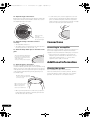
SRD1383A_IC621821D.book
1 ページ
2008年8月8日 金曜日 午後2時31分
In-Ceiling Speaker
Enceinte de plafond encastrable
S-IC621D
S-IC821D
Register your product at
http://www.pioneerelectronics.com (US)
http://www.pioneerelectronics.ca (Canada)
Operating Instructions
Mode d’emploi
SRD1383A_IC621821D.book
2 ページ
2008年8月8日 金曜日 午後2時31分
Thank you for buying this Pioneer product.
Please read through these operating instructions so you will know how to operate your model properly. After you have
finished reading the instructions, put them away in a safe place for future reference.
Introduction
This speaker system is designed for in-ceiling
installation. The design features provide for a wide range
of placement and listening position options.
Providing excellent sound quality, these models feature
an adjustable tweeter to provide flexibility of placement in
your listening area.
This speaker system is also paintable so that they may be
matched to your room decor.
Before you start
• The nominal impedance of this speaker system is
8 Ω. Connect the speaker system to an amplifier
capable of driving an impedance of at least 8 Ω.
This product incorporates auto-resetting overload
protection technology to help avoid damage to the
speakers. However, please observe the following
precautions:
• Do not supply amplification power to the speaker
system in excess of the maximum permissible
input, which could damage the speaker and cause
a hazard from overheating.
• If using a graphic equalizer to boost sounds in the
high-frequency range, do not use excessive
amplifier volume.
• Do not try to force a low-powered amplifier to
produce high sound levels as the amplifier’s
harmonic distortion will be increased, and you may
damage the speaker.
Caution: installation
• Pioneer is not responsible for any accidents or
damage that result from improper installation,
misuse, modification of the product, or natural
disasters.
• This speaker system must be installed by a qualified
technician as it involves such tasks as selecting a
location for installation, drilling holes in walls/ceiling,
wiring, and painting. Have the installer carefully
follow the installation instructions.
• The installation technician must follow professional
installation techniques to protect the speaker system
against falling.
• When installing the speakers, make sure that the
wall/ceiling is strong enough to support the
speakers.
• Improper installation of the speakers could cause
them to fall and cause damage or injuries to persons
nearby.
2
En
• Switch off and unplug your AV equipment and
consult the instructions when connecting up
components. Make sure you use the correct
connecting cables.
• Keep magnetic objects such as screwdrivers or steel
parts away from the tweeter and woofer speakers.
Since the speakers use strong magnets, the objects
may be attracted, causing injury or damaging the
diaphragm.
• Do not install the speakers where they will be in direct
sunlight, and avoid positioning them near heaters
and air conditioners. This may cause warping and
discoloration of the speaker and damage to the
speakers.
• Though this speaker system can be used in humid
areas (such as bathrooms or kitchens), do not install
it where it may be exposed to high temperatures,
such as in a sauna or near a cooking area, or where
water could splash on the speaker, which is not
waterproof.
Caution: in use
• If the speakers stop emitting sound after receiving
too large an input signal, turn down the volume
control on the amplifier and wait a few seconds. The
protection feature will be reset automatically.
For U.S. model
WARNING: Handling the cord on this product or
cords associated with accessories sold with the
product will expose you to chemicals listed on
proposition 65 known to the State of California and
other governmental entities to cause cancer and
birth defect or other reproductive harm.
Wash hands after handling
D36-P4_A_En
SRD1383A_IC621821D.book
3 ページ
2008年8月8日 金曜日 午後2時31分
What’s in the box
Installation
Standard setup
Grille x 1
Grille removal tool x 1
• This speaker system is designed to be used as a
single stereo speaker in small room (such as
bathrooms, closets, laundry rooms etc.). Usually it
should be located above the primary listening
position.
• Keep the speaker system at least 50 cm (20 in.) away
from the edge of the wall or ceiling. If this is not
possible, adjust the sound balance by using the
speakers’ treble level control.
TEMPLATE
GABARIT
Template x 1
Operating instructions
Sounds reproduced through speaker systems are easily
affected in subtle ways by the conditions in the listening
space. To assure optimum performance from this
speaker system, give adequate consideration to the
installation location before setup.
English
Paint mask x 1
(Transparent)
Butyl rubber tapes x 8
• This speaker system is not magnetically shielded. It
should therefore not be placed near TVs or monitors
that are sensitive to magnetic fields, as the
interaction of magnetic materials can cause
distortion of the colors on your TV screen. Magnetic
storage media (such as floppy discs and tape or video
cassettes) should also not be kept close to this
speaker system.
For the installer
• Give adequate consideration to the location of
installation before the setup of this speaker system.
• Check the walls/ceiling to see if they are strong
enough to withstand the weight of the speaker
system.
• Installation is possible on ceiling from 12.5 mm (1/2
in.) to 25 mm (1 in.) thick.
• Check the walls/ceiling to confirm there is no wiring,
plumbing, beams, studs or air conditioning systems
that may interfere with installation.
• Pioneer disclaims any liability whatsoever for
damage resulting from assembly, improper
mounting, insufficient reinforcement, misuse of the
product, acts of nature, etc.
3
En
SRD1383A_IC621821D.book
4 ページ
2008年8月8日 金曜日 午後2時31分
Painting the speakers
How to install
While the speaker and grille can be painted after it is
installed, painting it beforehand is much easier.
Make sure you have read and understood all the
information above, For the installer on page 3 and Before
installing above.
It is recommended to use spray paint, as brushed paint
may clog the holes in the grille and reduce the sound
quality significantly.
1 Remove the fabric scrim from the inside of the
grille.
Carefully peel off the fabric scrim and lay it down flat so
as not to get it wrinkled.
2 Use the supplied paint mask to cover the speaker.
If you don’t have the paint mask, use paper and masking
tape.
1 Once you have decided on the installation location,
prepare the supplied template.
Cut out the inside of the template along the dotted line
and discard the inner section.
2 Attach the template (outer section) to the wall/
ceiling using tape.
Make sure the template is aligned properly.
3 Trace a line onto the wall/ceiling, following the
inner perimeter of the template.
3 Paint the speaker and grille the desired color.
As previously mentioned, it is strongly recommended
that you paint before installation and that you use spray
paint.
4 After the speaker and grille have dried completely,
remove the paint mask and carefully replace the fabric
scrim on the back of the grille.
Before installing
• Before installing the speakers, run the speaker
cables to the installation location.
• To maximize sound quality, choose the correct
speaker gauge cables from the table below.
If the resistance of the speaker cable is too high, the
signal will be attenuated and the speakers’ frequency
response will be degraded.
AWG
feet
mm2
meters
16 or 14
less than 25
1.5 to 2.5
less than 8
14 or 12
25 to 50
2.5 to 4
8 to 16
12 or 10
50 to 75
4 to 6
16 to 24
10
more than 75
6
more than 24
4 Cut a hole where you have drawn the outline.
Be careful when cutting the hole, and use a proper
cutting tool.
5 Pull the speaker cable through the hole that has
been opened.
Be careful not to apply to much force when pulling on the
speaker cable or bend the cable at sharp angles.
6 Connect the cable wire to the speaker as shown
below.
When connecting the speakers, be careful not to touch
the diaphragms of the drivers.
Twist and pull off the protective
shields on each wire.
10 mm (0.4 in.)
Insert the speaker cable wires into the
holes while pressing down on the terminal
posts on the speaker, and then release the
terminal posts. For input terminal polarity,
red is positive (+) and black is negative (–).
• After connecting the wires, pull lightly on them to
make sure that the ends of the wires are securely
connected to the terminals. Poor connections can
create noise and interruptions in the sound.
4
En
SRD1383A_IC621821D.book
5 ページ
2008年8月8日 金曜日 午後2時31分
• If the wires are pulled out of the terminal posts and
the conductors come into contact with each other or
surrounding devices, an excessive additional load
may be placed on the amplifier. This may cause the
amplifier to stop functioning, and may even cause it
damage.
English
• Be careful to observe the correct polarity of the
connections between the cables and the speaker. If
the polarity (+, –) of one of the speakers (left or right)
is reversed the stereo image will be severely
degraded.
• When using electric screwdrivers, first find out the
minimum torque required for the installation of the
speaker system. Begin by setting the electric
screwdriver to its minimum torque and gradually
raise the torque until the screw starts to rotate. Check
what torque setting you are on at this point (this will
be the minimum torque required for the setup). After
confirming the torque, return the rotating clamps
toward the inside by reversing the direction of
rotation of the screws. When doing this, take care
that the screws do not come all the way out.
Rotating clamp
CAUTION
These speaker terminals carry HAZARDOUS LIVE
voltage. To prevent the risk of electric shock when
connecting or disconnecting the speaker cables,
disconnect the power cord before touching any
D3-4-2-2-3_A_En
uninsulated parts.
Speaker frame
Screw
7 Where available, use the fixing bracket located on
the back of the speaker system and attach a reinforced
wire, such as stainless steel wire rope, to the studs or
beams of the walls/ceiling.
• It is strongly recommended that you take double safe
precautions to prevent the speaker from falling by
accident.
10 Attach the speaker frame to the wall/ceiling, and
tighten the screws lightly (temporary attachment).
At this point the rotating clamp will rotate so that the
rotating clamp and frame are clamped on to the wall/
ceiling.
Stud/beam
Gently try pulling the speaker forward and check that all
of the rotating clamps have rotated outwards and are
lightly clamping to the wall/ceiling.
Reinforced wire
(not supplied)
11 Adjust the mounting orientation for the primary
listening position.
12 Tighten the screws firmly using no more than the
maximum torque specified.
Allowable maximum torque: 1.0 N⋅m
Fixing bracket
• Put the reinforced wire through the fixing bracket and
attach to the studs or beams. Make sure the stud/
beam that you are attaching it to is strong enough to
support the weight of the speaker system.
8 Place sound-absorbing material (such as fiberglass)
around the speakers as necessary to improve sound
quality.
Use only sound-absorbing materials that comply with
regional safety regulations.
• Screwing them in too tightly could break the rotating
clamps, twist the frames, damage the walls/ceilings
and make it difficult to attach the grille.
13 Make sure that the screws are not crooked and that
there is no gap between the wall/ceiling and frame.
9 Place the speaker into the hole you have cut.
Make sure the rotating clamps are turned inward.
• A Phillips screwdriver is required for loosening them.
5
En
SRD1383A_IC621821D.book
6 ページ
2008年8月8日 金曜日 午後2時31分
14 Adjust the angle of the tweeter.
Gently press the edge of the tweeter flange to adjust the
angle of the tweeter as desired. Be careful not to touch
the diaphragm while doing this.
• To remove the grille, use the supplied tool to hook
into the holes located near the edges and pull the
grille out. When doing this, make sure to pull the
edges out evenly. Forcing the grille out from one edge
alone will cause the grille to be deformed.
Make sure not to
touch the
diaphragm as it can
be easily damaged.
15 Adjust the setting of the treble control as
necessary.
• The standard setting is 0.
• The treble switch located in the front of the speaker
has two positions to choose from, +/0.
16 Attach the butyl rubber tapes on the inside of the
grille.
Attach the eight butyl rubber tapes
to each grille, lining up the butyl
rubber tapes to the marks on the
inside of the grille.
Then peel off the protective paper.
Connections
Connecting to an amplifier
Make sure you have read the connection instructions in
the manual supplied with the amplifier and that all
equipment is turned off before making any connections.
• When using a set of speakers connected to an
amplifier, you won’t be able to obtain the correct
stereo effect if the polarity (+, –) of one of the
speakers (left or right) is reversed.
Additional Information
17 Attach the grille to the speaker.
The grille is designed with a specific mounting
orientation. Gently push the grille onto the speaker, lining
up the one section of the edge of the grille to the groove
in the speaker. Then line up the entire grille to the groove
in the speaker and attach the grille by pressing in all
around the edge.
Orientate the grille so that the
notch is positioned adjacent to
the Pioneer logo.
Make sure to press on the
edges. Pressing on the
middle of the grille will
cause it to be deformed.
• Once you have pushed it in, make sure you press it
firmly against the speaker so that the grille doesn’t
fall off and cause an accident.
6
En
Cleaning the speaker
Use a dust brush to wipe off dust and dirt.
Never use furniture wax, cleaners, thinners, benzine,
insecticide sprays or other chemicals on or near the
speakers, since these will corrode the surfaces.
SRD1383A_IC621821D.book
7 ページ
2008年8月8日 金曜日 午後2時31分
Specifications
Speaker system
Accessories
Speaker units . . . . . . . . . . . . . . In-ceiling dual voice coil type
Paint mask . . . . . . . . . . . . . . . . . . . . . . . . . . . . . . . . . . . . . . . . 1
Grille . . . . . . . . . . . . . . . . . . . . . . . . . . . . . . . . . . . . . . . . . . . . . 1
Template . . . . . . . . . . . . . . . . . . . . . . . . . . . . . . . . . . . . . . . . . . 1
Butyl rubber tapes . . . . . . . . . . . . . . . . . . . . . . . . . . . . . . . . . . 8
Grille removal tool . . . . . . . . . . . . . . . . . . . . . . . . . . . . . . . . . . 1
Operating instructions
Configuration . . . . . . . . . . . . . . . . . . . . 16 cm (6 1/2 in.) 2-way
Woofer . . . . . . . . 16 cm (6 1/2 in.) Polypropylene cone type
Tweeter . . . . . . . . . . . . . . . . . . 2.5 cm (1 in.) Dome type x 2
Impedance. . . . . . . . . . . . . . . . . . . . . . . . . . . . . . . . . . . . . . 8 Ω
Frequency response . . . . . . . . . . . . . . . . . . . . 32 Hz to 25 kHz
Sensitivity. . . . . . . . . . . . . . . . . . . . . . . . . . . . . . . 89 dB (2.83 V)
Maximum input power . . . . . . . . . . . . . . . . . . . . 50 W + 50 W
Crossover frequency . . . . . . . . . . . . . . . . . . . . . . . . . . . 2.8 kHz
External dimensions . . . . . . . . . . . . . φ 294 mm x 113 (D) mm
φ
11 9/16 in. x 4 7/16 (D) in.
English
S-IC621D
• Specifications and design subject to modification
without notice.
Weight . . . . . . . . . . . . . . . . . . . . . . . . . . . . . . . 2.0 kg/4 lbs 7 oz
S-IC821D
Speaker units . . . . . . . . . . . . . . In-ceiling dual voice coil type
Configuration . . . . . . . . . . . . . . . . . . . . . . .20 cm (8 in.) 2-way
Woofer . . . . . . . . . . .20 cm (8 in.) Polypropylene cone type
Tweeter . . . . . . . . . . . . . . . . . . 2.5 cm (1 in.) Dome type x 2
Impedance. . . . . . . . . . . . . . . . . . . . . . . . . . . . . . . . . . . . . . 8 Ω
Frequency response . . . . . . . . . . . . . . . . . . . . 28 Hz to 25 kHz
Sensitivity. . . . . . . . . . . . . . . . . . . . . . . . . . . . . . . 91 dB (2.83 V)
Maximum input power . . . . . . . . . . . . . . . . . . . . 50 W + 50 W
Crossover frequency . . . . . . . . . . . . . . . . . . . . . . . . . . . 2.8 kHz
External dimensions . . . . . . . . . . . . . φ 294 mm x 113 (D) mm
φ 11 9/16 in. x 4 7/16 (D) in.
Weight . . . . . . . . . . . . . . . . . . . . . . . . . . . . . . . 2.0 kg/4 lbs 7 oz
7
En
SRD1383A_IC621821D.book
8 ページ
2008年8月8日 金曜日 午後2時31分
We Want You Listening For A Lifetime
Selecting fine audio equipment such as the unit
you’ve just purchased is only the start of your
musical enjoyment. Now it’s time to consider how
you can maximize the fun and excitement your
equipment offers. This manufacturer and the
Electronic Industries Association’s Consumer
Electronics Group want you to get the most out of
your equipment by playing it at a safe level. One that
lets the sound come through loud and clear without
annoying blaring or distortion-and, most importantly,
without affecting your sensitive hearing.
Sound can be deceiving. Over time your hearing
“comfort level” adapts to higher volumes of sound.
So what sounds “normal” can actually be loud and
harmful to your hearing. Guard against this by
setting your equipment at a safe level BEFORE your
hearing adapts.
Used wisely, your new sound equipment will
provide a lifetime of fun and enjoyment. Since
hearing damage from loud noise is often
undetectable until it is too late, this manufacturer
and the Electronic Industries Association’s
Consumer Electronics Group recommend you avoid
prolonged exposure to excessive noise. This list of
sound levels is included for your protection.
Decibel
Level Example
30
40
50
60
70
80
Quiet library, soft whispers
Living room, refrigerator, bedroom away from traffic
Light traffic, normal conversation, quiet office
Air conditioner at 20 feet, sewing machine
Vacuum cleaner, hair dryer, noisy restaurant
Average city traffic, garbage disposals, alarm clock
at two feet.
THE FOLLOWING NOISES CAN BE DANGEROUS
UNDER CONSTANT EXPOSURE
To establish a safe level:
• Start your volume control at a low setting.
• Slowly increase the sound until you can hear it
comfortably and clearly, and without distortion.
90 Subway, motorcycle, truck traffic, lawn mower
100 Garbage truck, chain saw, pneumatic drill
120 Rock band concert in front of speakers,
thunderclap
140 Gunshot blast, jet plane
180 Rocket launching pad
Once you have established a comfortable sound
level:
• Set the dial and leave it there.
Information courtesy of the Deafness Research Foundation.
Taking a minute to do this now will help to prevent
hearing damage or loss in the future. After all, we
want you listening for a lifetime.
S001_En
8
En
SRD1383A_IC621821D.book
9 ページ
2008年8月8日 金曜日 午後2時31分
English
9
En
06_SRD1383A_Fr.fm
2 ページ
2008年8月8日 金曜日 午後12時59分
Nous vous remercions d’avoir acheté ce produit Pioneer.
Veuillez lire attentivement ce mode d’emploi de manière à pouvoir utiliser votre modèle correctement. Après avoir lu
ces explications, conservez-les en lieu sûr pour éventuellement les consulter plus tard.
Introduction
Cette enceinte acoustique est conçue en vue d’une
installation au plafond. Les particularités du design
permettent de répondre à une large gamme de
dispositions et de positions d’écoute.
Tout en procurant une excellent qualité sonore, ces
modèles possèdent un tweeter ajustable qui accroît leur
souplesse du positionnement dans votre salle d’écoute.
Cette enceinte acoustique peut être peinte, ce qui vous
permet de mieux l’intégrer à votre décoration intérieure.
Avant de commencer
• L’impédance nominale de ces enceintes acoustiques
est de 8 Ω. Raccordez l’enceinte acoustique à une
amplificateur capable de convenir à une impédance
d’au moins 8 Ω.
Pour éviter d’endommager les haut-parleurs, cet appareil
incorpore une technologie de remise à zéro automatique
comme protection contre la surcharge. Toutefois,
respectez les instructions suivantes :
• Ne fournissez pas aux enceintes une puissance
d’amplification supérieure à l’entrée maximale
admissible, afin de ne pas endommager les hautparleurs et d’éviter tout danger par surchauffe.
• Si vous utilisez un égaliseur graphique pour
accentuer les sons dans la plage des hautes
fréquences, n’élevez pas trop le volume de
l’amplificateur.
• N’essayez pas de pousser un amplificateur de
faible puissance à produire de hauts niveaux
sonores, car la distorsion harmonique de
l’amplificateur en serait accentuée et vous
pourriez endommager les haut-parleurs.
Attention : installation
• Pioneer n’assume aucune responsabilité en cas
d’accidents ou de dégâts résultant d’une installation
inappropriée, d’une erreur d’utilisation, d’une
altération du produit et/ou de catastrophes
naturelles.
• L’installation de cette enceinte acoustique doit être
confiée à un technicien qualifié, car elle nécessite
des tâches comme la sélection d’un endroit
d’installation, le forage de trous dans des murs/
plafond, le câblage et la peinture de certains
éléments. Demandez à l’installateur de respecter
fidèlement les instructions suivantes.
• Le technicien doit respecter les techniques
d’installation professionnelles pour éviter la chute
des enceintes acoustiques.
2
Fr
• A l’installation de l’enceinte, assurez-vous que le
mur/plafond est assez résistant pour la supporter.
• Une installation inadéquate de l’enceinte pourrait
être à l’origine de sa chute qui causerait des dégâts
voire des blessures.
• Mettez votre appareil audiovisuel hors tension et
débranchez-le, puis consultez le mode d’emploi
avant de brancher des composants. Prenez soin
d’utiliser correctement les câbles de raccordement.
• Tenez des objets magnétisés, tels que tournevis ou
pièces en acier, à l’écart des haut-parleurs aigus et
graves. Comme ces haut-parleurs utilisent des
aimants puissants, ces objets pourraient y être
attirés, provoquant des dégâts aux haut-parleurs ou
endommageant leur diaphragme.
• N’installez pas les enceintes en plein soleil et évitez
de les placer près d’appareils de chauffage ou de
climatiseurs. Ceci pourrait gondoler et décolorer le
coffret des enceintes et endommager leurs hautparleurs.
• Bien que cette enceinte acoustique soit utilisable
dans un endroit humide comme une salle de bain ou
une cuisine, ne la placez pas là ou elle serait exposée
à de hautes températures comme dans un sauna ou
près d’une table de cuisson, ou à un emplacement ou
elle serait éclaboussée, car elle n’est pas étanche.
Attention : à l’emploi
• Si les haut-parleurs cessent d’émettre des sons
après la réception d’un signal d’entrée trop puissant,
réduisez le volume sur l’amplificateur et attendez
quelques secondes. Cette fonction de protection sera
automatiquement réinitialisée.
06_SRD1383A_Fr.fm
3 ページ
2008年8月8日 金曜日 午後12時59分
Contenu de l’emballage
Installation
Configuration standard
Masque de peinture x 1
(Transparent)
Outil de retrait de grille
x1
Gabarit x 1
Mode d’emploi
Bandes en caoutchouc
butyle x 8
• Cette enceinte est conçue pour servir comme
enceinte stéréo simple dans un petit local, tel qu’une
salle de bain, un placard, une buanderie. etc.
Habituellement, elle doit être située au-dessus de la
position d’écoute normale.
• Placez l’enceinte à 50 cm au moins du bord du mur
ou du plafond. Si ce n’est pas possible, ajustez la
balance sonore au moyen de la commande de niveau
des aigus des enceintes.
Français
TEMPLATE
GABARIT
Grille x 1
Les sons reproduits par les enceintes acoustiques sont
facilement affectés de manière subtile par les conditions
du local d’écoute. Pour obtenir des performances
optimales de cette enceinte, prenez en considération
l’emplacement d’installation avant la configuration.
• Ces enceintes acoustiques ne sont pas pourvues
d’un blindage magnétique. Elles ne doivent donc pas
être placées près de téléviseurs ou de moniteurs
sensibles aux champs magnétiques, car l’interaction
des matériaux magnétiques peut provoquer une
distorsion des couleurs sur l’écran du téléviseur. Des
supports de mémorisation magnétique (tels que
disquettes, cassettes audio ou vidéo) doivent aussi
être tenus à l’écart de cette enceinte acoustique.
A l’intention de l’installateur
• Réfléchissez bien à l’emplacement d’installation
avant de configurer cette enceinte acoustique.
• Examinez les murs/plafond pour voir s’ils sont assez
solides pour résister au poids de l’enceinte.
• Une installation est possible sur des plafonds de
12,5 mm à 25 mm d’épaisseur.
• Examinez les murs/plafonds pour vous assurer qu’ils
ne contiennent pas de fils, tuyaux, poutres, montants
ou canalisations de climatisation qui pourraient
gêner l’installation.
• Pioneer rejette toute responsabilité en cas de dégâts
causés par un assemblage et un montage
inadéquats, un renforcement insuffisant, une erreur
d’utilisation, des catastrophes naturelles, etc.
3
Fr
06_SRD1383A_Fr.fm
4 ページ
2008年8月8日 金曜日 午後12時59分
Peinture des enceintes
Méthode d’installation
Bien que l’enceinte et la grille puissent être peintes après
leur installation, il est plus facile de le faire avant leur
installation.
Veuillez lire de manière à les comprendre toutes les
informations ci-avant sous : A l’intention de l’installateur
la page 3 et Avant l’installation ci-dessus.
Il est conseillé d’utiliser de la peinture par pulvérisation,
car une peinture au pinceau bouchera les orifices de la
grille et réduira considérablement la qualité des sons.
1 Enlevez le diffuseur en tissu par l’intérieur de la
grille.
Décollez délicatement le diffuseur en tissu et posez-le à
plat de sorte qu’il ne fasse pas de pli.
2 Utilisez le masque de peinture fourni pour recouvrir
l’enceinte.
Si vous n’avez pas de masque de peinture, utilisez un
papier ou une bande de masquage.
1 Lorsque vous avez décidé l’endroit d’installation,
préparez le gabarit fourni.
Découpez l’intérieur du gabarit le long de la ligne
pointillée et débarrassez-vous de la section intérieure.
2 Fixez le gabarit (section externe) sur le mur/plafond
au moyen de ruban adhésif.
Assurez-vous que le gabarit est correctement aligné.
3 Tracez une ligne sur le mur/plafond en suivant le
périmètre interne du gabarit.
3 Appliquez la couleur souhaitée sur l’enceinte et la
grille.
Comme déjà mentionné, il est conseillé de peindre avant
l’installation et d’utiliser une peinture par pulvérisation.
4 Une fois que l’enceinte et la grille sont
complètement sèches, retirez le masque de peinture et
replacez délicatement le diffuseur en tissu sur la grille.
4 Découpez un trou à l’endroit ou vous avez tracé
le contour.
Agissez avec prudence pour découper le trou et utilisez
un outil approprié.
Avant l’installation
• Avant l’installation des enceintes, cheminez les
câbles d’enceinte vers l’endroit d’installation.
• Pour optimiser la qualité sonore, choisissez des
câbles d’enceinte du calibre correct en consultant le
tableau suivant.
Si la résistance du câble d’enceinte est trop élevée, le
signal sera atténué et la réponse en fréquence des
enceintes sera amoindrie.
mm2
mètres
1,5 à 2,5
moins de 8
2,5 à 4
8 à 16
4à6
16 à 24
6
plus de 24
5 Faites passer le câble d’enceinte par le trou qui a été
découpé.
Veillez à ne pas tirer fortement sur le câble d’enceinte et
à ne pas le plier à un angle aigu.
6 Connectez le câble d’enceinte sur l’enceinte
comme illustré ci-après.
Lors du branchement des enceintes, veillez à ne pas
toucher le diaphragme des haut-parleurs.
Torsadez et enlevez la gaine
protectrice au bout de chaque fil.
10 mm
Insérez les fils du câble d’enceinte dans
l’orifice des bornes en appuyant sur la
borne prévue sur l’enceinte, puis en la
relâchant pour immobiliser le fil. En ce qui
concerne les polarités des bornes, la
rouge est positive (+) et la noire est
négative (–).
4
Fr
06_SRD1383A_Fr.fm
5 ページ
2008年8月8日 金曜日 午後12時59分
• Après avoir branché les fils, tirez légèrement sur
ceux-ci pour vous assurer que leur extrémité est
parfaitement immobilisée sur les bornes. De
mauvaises connexions sont la source de parasites,
voire d’interruptions des sons.
• Si les fils des câbles d’enceinte ressortent des bornes
et qu’un contact s’établit entre eux ou avec un
dispositif métallique voisin, l’amplificateur risque de
subir une charge anormale. Ceci peut provoquer une
interruption de l’amplificateur, voire endommager
celui-ci.
ATTENTION
• Un tournevis à pointe cruciforme est nécessaire pour
les desserrer.
• Avant d’utiliser des tournevis électriques, vérifiez au
préalable le couple minimum requis pour
l’installation des enceintes. Commencez par régler le
tournevis électrique à son couple minimal et
augmentez progressivement le couple jusqu’à ce que
le tournevis commence à tourner. Vérifiez le réglage
du couple à ce stade (ceci sera le couple minimal
requis pour la configuration). Après avoir confirmé le
couple, ramenez les brides rotatives vers l’intérieur
en inversant le sens de la rotation de vis. A ce stade,
assurez-vous que les vis ne ressortent pas
complètement.
Les bornes des haut-parleurs sont sous une tension
ACTIVE DANGEREUSE. Pour éviter tout risque de
décharge électrique lors du branchement et du
débranchement des câbles de haut-parleur, débranchez
le cordon d’alimentation avant de toucher des parties
D3-4-2-2-3_A_Fr
non isolées.
Bride rotative
Français
• Veillez à respecter la polarité correcte des
connexions entre les câbles et les enceintes. Si la
polarité (+, –) d’une des enceintes (gauche ou droite)
est inversée, l’image stéréo sera sérieusement
dégradée.
9 Placez l’enceinte dans l’orifice que vous avez
découpé.
Assurez-vous que les brides rotatives sont tournées vers
l’intérieur.
Collier d’enceinte
Vis
7 Quand c’est possible, utilisez l’applique de fixation
prévue à l’arrière de l’enceinte et fixez un cordage
renforcé, tel qu’un cordon à fils d’acier inoxydable, à
des montants ou des poutres sur les murs/plafond.
Attention
• Il est vivement conseillé de prendre de sérieuses
précautions pour éviter une chute accidentelle des
enceintes.
Montant/poutre
Cordage renforcé
(non fourni)
10 Fixez le collier d’enceinte sur le mur ou le plafond,
puis serrez légèrement les vis (fixation temporaire).
A ce stade, la bride rotative tournera de sorte que celle-ci
et le collier soient immobilisés sur le mur ou au plafond.
Tirez délicatement l’enceinte vers l’avant pour vérifier
que toutes les brides rotatives sont tournées vers
l’extérieur et qu’elles sont légèrement fixées sur le mur
ou le plafond.
11 Ajustez l’orientation de montage en vue de la
position d’écoute principale.
12 Serrez fermement les vis en respectant le couple
maximal spécifié.
Couple maximum autorisé : 1.0 N⋅m
Applique de fixation
• Passez le cordage renforcé par l’applique de fixation
et fixez-le sur des montants ou des poutres. Assurezvous que le montant ou la poutre est suffisamment
résistant pour supporter le poids de l’enceinte.
Attention
• Un serrage excessif pourrait briser les brides
rotatives, tordre les colliers d’enceinte, endommager
les murs ou le plafond et rendre difficile la fixation de
la grille.
8 Au besoin, placez un matériau isolant, tel que de la
fibre de verre, autour des enceintes pour améliorer la
qualité du son.
Utilisez uniquement un matériau isolant qui respecte les
règlements régionaux en matière de sécurité.
5
Fr
06_SRD1383A_Fr.fm
6 ページ
2008年8月8日 金曜日 午後12時59分
13 Assurez-vous que les vis ne sont pas inclinées et
qu’il n’y a pas d’espace entre le mur/plafond et le
collier.
14 Ajustez l’angle du tweeter
Appuyez délicatement sur le bord du flasque du tweeter
pour ajuster son angle selon les besoins. Veillez à ne pas
toucher le diaphragme lors de ce réglage.
Ne touchez pas le
diaphragme car il
peut facilement être
endommagé.
15 Ajustez le réglage de la commande des aigus selon
les besoins.
• Le réglage standard est 0.
• Le commutateur des aigus prévu sur l’avant de
l’enceinte a deux positions au choix : +/0.
16 Fixez la bande en caoutchouc butyle sur l’intérieur
de la grille.
Fixez les huit bandes de
caoutchouc butyle sur chaque
grille en alignant les bandes sur
l’intérieur de la grille.
Décollez ensuite le papier de
protection.
17 Fixez la grille sur l’enceinte.
La grille doit être montrée dans un sens seulement.
Insérez délicatement la grille sur l’enceinte, en alignant
une section du bord de la grille sur la rainure de
l’enceinte. Alignez ensuite toute la grille avec la rainure
de l’enceinte et fixez la grille en poussant tout autour du
bord.
Orientez la grille de sorte que
l’encoche soit positionnée à
côté du logo Pioneer.
Veillez à pousser sur les
bords. Une pression au
milieu de la grille pourrait la
déformer.
• Après avoir enfoncé la grille, assurez-vous qu’elle est
fermement maintenue contre l’enceinte et qu’elle ne
risque donc pas de tomber.
6
Fr
• Pour retirer la grille, servez-vous de l’outil fourni pour
accrocher les orifices prévus près des bords et
détacher ainsi la grille. A ce moment, prenez soin de
tirer les bords d’une manière égale. La grille pourrait
être déformée si vous forcez son retrait par un bord.
Connexions
Branchement à un amplificateur
Veillez à lire toutes les instructions relatives aux
connexions dans le mode d’emploi (fourni avec
l’amplificateur) et à ce que tous les équipements soient
hors tension avant d’effectuer les branchements.
• A l’emploi d’un jeu d’enceintes raccordé à un
amplificateur, si la polarité (+, –) d’une des enceintes
acoustiques (gauche ou droite) est inversée, vous
n’obtiendrez pas un effet stéréophonique normal.
Information
complémentaire
Entretien de l’enceinte
Servez-vous d’une brosse douce pour enlever la
poussière et la saleté.
N’employez jamais de cire pour meubles, détergent,
diluant, benzine, insecticide en atomiseur et autre
produit chimique sur ou à proximité des enceintes, car
cela endommagerait leurs surfaces.
06_SRD1383A_Fr.fm
7 ページ
2008年8月8日 金曜日 午後12時59分
Fiche technique
Enceinte acoustique
S-IC621D
Accessoires
Enceintes
. . . . .Type encastré au plafond à double bobine d’excitation
Configuration . . . . . . . . . . . . . . . . . . . . . . . . . . 16 cm, 2 voies
Haut-parleur graves
. . . . . . . . . . . . . . . Type à cône de polypropylène de 16 cm
Haut-parleur des aigus. . . . . . .Type à dôme x 2, de 2,5 cm
Impédance. . . . . . . . . . . . . . . . . . . . . . . . . . . . . . . . . . . . . . 8 Ω
Réponse de fréquence . . . . . . . . . . . . . . . . . . . 32 Hz à 25 kHz
Sensibilité . . . . . . . . . . . . . . . . . . . . . . . . . . . . . . 89 dB (2,83 V)
Puissance d’entrée maximum. . . . . . . . . . . . . . 50 W + 50 W
Fréquence de recouvrement . . . . . . . . . . . . . . . . . . . . 2,8 kHz
Dimensions externes . . . . . . . . . . . . φ 294 mm x 113 (P) mm
Poids . . . . . . . . . . . . . . . . . . . . . . . . . . . . . . . . . . . . . . . . 2,0 kg
Masque de peinture . . . . . . . . . . . . . . . . . . . . . . . . . . . . . . . . 1
Grille . . . . . . . . . . . . . . . . . . . . . . . . . . . . . . . . . . . . . . . . . . . . . 1
Gabarit . . . . . . . . . . . . . . . . . . . . . . . . . . . . . . . . . . . . . . . . . . . 1
Bandes en caoutchouc butyle . . . . . . . . . . . . . . . . . . . . . . . . 8
Outil de retrait de grille . . . . . . . . . . . . . . . . . . . . . . . . . . . . . . 1
Mode d’emploi
• Spécifications et design sous réserve de
modifications sans préavis.
Français
S-IC821D
Remarque
Enceintes
. . . . .Type encastré au plafond à double bobine d’excitation
Configuration . . . . . . . . . . . . . . . . . . . . . . . . . . 20 cm, 2 voies
Haut-parleur graves
. . . . . . . . . . . . . . . Type à cône de polypropylène de 20 cm
Haut-parleur des aigus. . . . . . .Type à dôme x 2, de 2,5 cm
Impédance. . . . . . . . . . . . . . . . . . . . . . . . . . . . . . . . . . . . . . 8 Ω
Réponse de fréquence . . . . . . . . . . . . . . . . . . . 28 Hz à 25 kHz
Sensibilité . . . . . . . . . . . . . . . . . . . . . . . . . . . . . . 91 dB (2,83 V)
Puissance d’entrée maximum. . . . . . . . . . . . . . 50 W + 50 W
Fréquence de recouvrement . . . . . . . . . . . . . . . . . . . . 2,8 kHz
Dimensions externes . . . . . . . . . . . . φ 294 mm x 113 (P) mm
Poids . . . . . . . . . . . . . . . . . . . . . . . . . . . . . . . . . . . . . . . . 2,0 kg
7
Fr
SRD1383A_IC621821D.book
8 ページ
2008年8月8日 金曜日 午後2時31分
Should this product require service in the U.S.A. and you wish to locate the nearest Pioneer
Authorized Independent Service Company, or if you wish to purchase replacement parts,
operating instructions, service manuals, or accessories, please call the number shown
below.
1–800–421–1404
Please do not ship your product to Pioneer without first calling the Customer Support at the
above listed number for assistance.
Pioneer Electronics Service, Inc.
P.O. BOX 1760, Long Beach,
CA 90801-1760, U.S.A.
For warranty information please see the Limited Warranty sheet included with your product.
Should this product require service in Canada, please contact a Pioneer Canadian
Authorized Dealer to locate the nearest Pioneer Authorized Service Company in Canada.
Alternatively, please contact the Customer Satisfaction Department at the following address:
Pioneer Electronics of Canada, Inc.
Customer Satisfaction Department
300 Allstate Parkway, Markham, Ontario L3R 0P2
1-877-283-5901
905-479-4411
For warranty information please see the Limited Warranty sheet included with your product.
Si ce produit doit être réparé au Canada, veuillez vous adresser à un distributeur autorisé
Pioneer du Canada pour obtenir le nom du Centre de Service Autorisé Pioneer le plus près
de chez-vous. Vous pouvez aussi contacter le Service à la clientèle de Pioneer:
Pioneer Électroniques du Canada, Inc.
Service Clientèle
300, Allstate Parkway, Markham, Ontario L3R 0P2
1-877-283-5901
905-479-4411
Pour obtenir des renseignements sur la garantie, veuillez vous reporter au feuillet sur la
garantie restreinte qui accompagne le produit.
S018_C_EF
Published by Pioneer Corporation.
Copyright © 2008 Pioneer Corporation.
All rights reserved.
Publication de Pioneer Corporation.
© 2008 Pioneer Corporation.
Tous droits de reproduction et de traduction réservés.
Printed in Malaysia
Imprimé en Malaisie
PIONEER CORPORATION
4-1, Meguro 1-Chome, Meguro-ku, Tokyo 153-8654, Japan
PIONEER ELECTRONICS (USA) INC.
P.O. BOX 1540, Long Beach, California 90801-1540, U.S.A. TEL: (800) 421-1404
PIONEER ELECTRONICS OF CANADA, INC.
300 Allstate Parkway, Markham, Ontario L3R 0P2, Canada TEL: 1-877-283-5901, 905-479-4411
PIONEER EUROPE NV
Haven 1087, Keetberglaan 1, B-9120 Melsele, Belgium TEL: 03/570.05.11
PIONEER ELECTRONICS ASIACENTRE PTE. LTD.
253 Alexandra Road, #04-01, Singapore 159936 TEL: 65-6472-7555
PIONEER ELECTRONICS AUSTRALIA PTY. LTD.
178-184 Boundary Road, Braeside, Victoria 3195, Australia, TEL: (03) 9586-6300
PIONEER ELECTRONICS DE MEXICO S.A. DE C.V.
Blvd.Manuel Avila Camacho 138 10 piso Col.Lomas de Chapultepec, Mexico,D.F. 11000 TEL: 55-9178-4270
<SRD1383-A>