1
SyncMaster 320MX-3, 320MXN-3
320MP-3, 320MPN-3
LCD Display
User Manual
The color and the appearance may differ depending on the
product, and the specifications are subject to change
without prior notice to improve the performance.
Safety Instructions
Notational
Note
These safety instructions must be followed to ensure your safety and prevent property damage.
Make sure to read the instructions carefully and use the product in the correct manner.
Warning / Caution
Failure to follow directions noted by this symbol could result in bodily
harm or damage to the equipment.
Note
Prohibited
Important to read and understand at all times
Do not disassemble
Disconnect the plug from the
outlet
Do not touch
Ground to prevent an electric
shock
Power
When not used for extended period of time, set your computer to DPM.
If using a screen saver, set it to active screen mode.
The images here are for reference only, and are not applicable in all cases
(or countries).
Shortcut to Anti-Afterimage Instructions
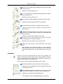
Do not use a damaged power cord or plug or a damaged or
loose power outlet.
•
Otherwise, this may result in electric shock or fire.
Do not touch the power plug with wet hands when removing or
plugging the plug into the outlet.
•
Otherwise, this may result in electric shock.
Make sure to connect the power cord to a grounded power outlet.
•
Otherwise, it may result in electric shock or personal injury.
Safety Instructions
Ensure that the power plug is plugged into the power outlet
firmly and correctly.
•
Otherwise, this may result in fire.
Do not forcefully bend or pull the power plug and do not place
any heavy material on it.
•
Otherwise, this may result in fire.
Do not connect multiple appliances to the same power outlet.
•
Otherwise, this may cause fire due to overheating.
Do not disconnect the power cord while using the product.
•
Otherwise, this may result in damage to the product due to
electric shock.
To disconnect the apparatus from the mains, the plug must be
pulled out from the mains socket, therefore the mains plug shall
be readily operable.
•
Otherwise, this may cause electric shock or fire.
Use only the power cord provided by our company. Do not use
the provided power cord of another product.
•
Otherwise, this may result in fire or electric shock.
Connect the power plug to a wall outlet that can be easily
reached.
•
When a problem occurs with the product, you must unplug the
power plug to cut the power off completely. You cannot cut the
power off completely using only the power button on the product.
Installation
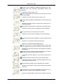
Be sure to contact an authorized Service Center when installing your
monitor in a location with heavy dust, high or low temperatures, high humidity, and exposed to chemical substances and where it operates for 24
hours such as at airports, train stations etc.
Failure to do so may cause serious damage to your monitor.
Ensure that at least two persons lift and move the product.
•
Otherwise, it may be dropped and cause personal injury, and/
or damage the product.
When installing the product in a cabinet or rack, make sure that
the front end of the bottom of the product does not project out.
•
Otherwise, it may fall or cause personal injury.
•
Use a cabinet or rack of a size appropriate to the product.
Safety Instructions
DO NOT PLACE CANDLES, MOSQUITO REPELLANT, CIGARETTES AND ANY HEATING APPLIANCES NEAR THE
PRODUCT.
•
Otherwise, this may result in fire.
Keep heating appliances as far away from the power cord or the
product as possible.
•
Otherwise, this may result in electric shock or fire.
Do not install it in a badly ventilated location such as a bookcase
or closet.
•
Otherwise, this may result in fire due to an increase in the internal temperature.
When putting the product down, make sure to put it down softly.
•
Otherwise, this may result in damage to the screen display.
Do not place the front of the product on the floor.
•
Otherwise, this may result in damage to the screen display.
Ensure that an authorized installation company installs the wall
mount.
•
Otherwise, it may fall and cause personal injury.
•
Make sure to install the specified wall mount.
Install your product in a well ventilated location. Ensure that
there is a clearance of more than 4 inches (10 cm) from the wall.
•
Otherwise, it may result in fire due to an increase in the internal
temperature.
Bend the outdoor antenna cable downwards at the location
where it goes in so that rainwater does not flow in.
•
If rainwater enters the product, it may result in electric shock
or fire.
Install the antenna far away from any high voltage cables.
•
If the antenna touches or falls onto a high voltage cable, it may
result in electric shock or fire.
Ensure that the packaging vinyl is kept away from children.
•
Otherwise, it may result in serious harm (suffocation) if children
play with it.
If the height of your monitor is adjustable, do not place any object or part of your body on the stand when lowering it.
•
This may cause damage to the product or the person carrying
it.
Safety Instructions
Clean
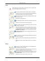
When cleaning the monitor case or the surface of the TFT-LCD screen,
wipe with a slightly moistened, soft cloth.
Do not spray cleaner directly onto the surface of the product.
•
Otherwise, this may result in the discoloration and distortion of
the structure and the screen surface may peel off.
When cleaning the power plug pins or dusting the power outlet,
clean it with a dry cloth.
•
Otherwise, it may result in fire.
When cleaning the product, make sure to disconnect the power
cord.
•
Otherwise, it may result in electric shock or fire.
When cleaning the product, disconnect the power cord and
clean it with a soft, dry cloth.
•
(Do not use chemicals such as wax, benzene, alcohol, thinner,
mosquito repellant, lubricant, or cleaner.) These may change
the appearance of the product surface and peel off the indication labels on the product.
Since the product housing is easily scratched, make sure to use
the specified cloth only.
When cleaning the product, do not spray water directly onto the
main body of the product.
•
Ensure that water does not enter the product and that it is not
wet.
•
Otherwise, this may result in electric shock, fire or a malfunction.
Others
The product is a high voltage product. Do not disassemble, repair or modify the product yourself.
•
Otherwise, this may result in electric shock or fire. If the product
needs to be repaired, contact a Service Center.
If there is a strange smell or a strange sound or smoke is coming
from the product, disconnect the power plug immediately and contact a Service Center.
•
Otherwise, this may result in electric shock or fire.
Safety Instructions
Do not place this product in a location exposed to moisture, dust,
smoke, water, or in a car.
•
Otherwise, this may result in electric shock or fire.
When you drop the product or the case is broken, turn the power
off and disconnect the power cord. Contact a Service Center.
•
Otherwise, this may result in electric shock or fire.
If thunder or lightning is occurring, do not touch the power cord
or antenna cable.
•
Otherwise, this may result in electric shock or fire.
Do not try to move the monitor by pulling only the wire or the
signal cable.
•
Otherwise, it may fall and result in electric shock, damage to
the product or fire due to damage to the cable.
Do not lift or move the product back and forwards or right and
left while only holding the power cord or signal cables.
•
Otherwise, it may fall and result in electric shock, damage to
the product or fire due to damage to the cable.
Make sure that the ventilating opening is not blocked by a table
or curtain.
•
Otherwise, it may result in fire due to an increase in the internal
temperature.
Do not place any containers containing water, vases, flowerpots, medicines as well as any metal on the product.
•
If water or a foreign material enters the product, disconnect the
power cord and contact a Service Center.
•
This may result in a product malfunction, electric shock, or fire.
Do not use or keep combustible spray or flammable material
near the product.
•
Otherwise, this may result in an explosion or fire.
Do not insert any metal, such as chopsticks, coins, pins and
steel, or flammable objects, such as matches or paper, inside the
product (through the ventilating openings, input and output terminals, etc).
•
If water or foreign material enters the product, disconnect the
power cord and contact a Service Center.
•
Otherwise, this may result in electric shock or fire.
When using a fixed screen for a long time, an afterimage or stain
may occur.
•
If you are not using your product for a long period of time, put
it into sleep mode or use a moving screen saver.
Safety Instructions
Set a resolution and frequency appropriate to the product.
•
Otherwise, your eyesight may be damaged.
When using headphones or earphones, do not turn the volume
too high.
•
Having the sound too loud may damage your hearing.
To avoid eyestrain, do not sit too close to the product.
Take a rest for at least five (5) minutes after using the monitor
for one (1) hour.
This reduces eye fatigue.
Do not install it in an unstable location such as an unstable rack
or uneven surface or a location exposed to vibrations.
•
Otherwise, it may fall and cause personal injury and/or damage
the product.
•
If you use the product in a location exposed to vibrations, it may
damage the product and result in fire.
When moving the product, turn the power off and disconnect
the power plug, antenna cable, and all the cables connected to the
product.
•
Otherwise, it may result in electric shock or fire.
Ensure that children do not hang onto the product or climb up
onto the product.
•
The product may fall and cause personal injury or death.
If you do not use the product for a long period of time, disconnect
the power cord from the power outlet.
•
Otherwise, this may result in overheating or fire due to dust,
and may result in fire due to electric shock or leakage.
Do not place any heavy items or toys or confectionery, such as
cookies etc. that may attract the attention of children and to the
product.
•
Your children may hang onto the product causing it to fall and
this may result in personal injury or death.
Be careful that children do not place the battery in their mouths
when removed from the remote control. Place the battery in a location that children or infants cannot reach.
•
If children have had the battery in their mouths, consult your
doctor immediately.
Safety Instructions
When replacing the battery, insert it with the right polarity (+, -).
•
Otherwise, the battery may become damaged or it may cause
fire, personal injury or damage due to leakage of the internal
liquid.
Use only the specified standardized batteries, and do not use a
new battery and a used battery at the same time.
•
Otherwise, the batteries may be damaged or cause fire, personal injury or damage due to a leakage of the internal liquid.
The batteries (and rechargeable batteries) are not ordinary refuse and must be returned for recycling purposes. The customer
is responsible for returning the used or rechargeable batteries for
recycling.
•
The customer can return used or rechargeable batteries to a
nearby public recycling center or to a store selling the same
type of the battery or rechargeable battery.
Do not place the product in a location exposed to direct sunlight
or near any heat such as a fire or heater.
•
This may reduce the lifetime of the product, and may result in
fire.
Do not drop any objects onto the product or cause any impact
to the product.
•
Otherwise, this may result in electric shock or fire.
Do not use a humidifier near the product.
•
Otherwise, this may result in electric shock or fire.
When there is a gas leak, do not touch the product or the power
plug; ventilate immediately.
•
If a spark occurs, it may cause an explosion or fire.
If the product has been turned on for a long time, the display
panel becomes hot. Do not touch it.
Keep the small accessories in a location out of the reach of
children.
Be careful when adjusting the angle of the product or the height
of the stand.
•
This may result in personal injury as your hand or fingers may
become caught.
•
Also, if you tilt the product too far, it may fall and cause personal
injury.
Safety Instructions
Do not install the product in a location low enough for children
to reach.
•
Otherwise, it may fall and result in personal injury.
•
Since the front part of the product is heavy, install the product
on a level and stable surface.
Do not put any heavy objects on the product.
•
This may result in personal injury and/or damage to the product.
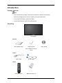
Introduction
Package Contents
Note
•
After unpacking the package, make sure to check the contents of the package.
•
Store the packaging box in case you need to move the Product later.
•
If any items are missing, contact your dealer.
•
Contact a local dealer to purchase optional items.
Unpacking
LCD Display
Manuals
Quick Setup Guide
Warranty Card
(Not available in all locations)
Cables
Power Cord
D-Sub Cable
Others
Remote Control
Batteries (AAA X 2)
User's Guide
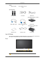
Introduction
Others
(BP59-00138B)
(Not available in all locations)
Sold separately
Semi Stand KIT
LAN Cable
USB Cable
(Applicable to the MXn-3, MPN-3
model only)
RGB to BNC Cable
RGB to COMPONENT Cable
Wall Mount KIT
RS232C Cable
Network Box
(Applicable to the MX-3,MP-3
model only)
TV tuner box
Your LCD Display
The color and the appearance may differ depending on the product, and the specifications
are subject to change without prior notice to improve the performance.
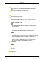
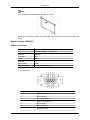
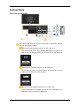
Front
MENU button [MENU]
Introduction
Opens the on-screen menu and exits from the menu. Also use to exit the
OSD menu or return to the previous menu.
Navigate buttons (Up-Down buttons)
Moves from one menu item to another vertically or adjusts selected menu
values.
Adjust buttons (Left-Right buttons) / Volume buttons
Moves from one menu item to another horizontally or adjusts selected
menu values. When OSD is not on the screen, press the button to adjust
volume.
ENTER button [ENTER]
Activates a highlighted menu item.
SOURCE button [SOURCE]
Switches from PC mode to Video mode. Selects the input source that an
external device is connected to.
[PC] → [DVI] → [AV] → [Component] → [HDMI1] → [HDMI2] → [DisplayPort] → [MagicInfo] → [TV]
Note
•
The [RGB/COMPONENT IN] port is compatible with RGB (PC) and
Component signals.
However, the picture may display abnormally if the connected external
input signal is different from the selected video signal.
•
A TV tuner box (sold separately) must be connected to use the TV.
Note
Using MagicInfo
•
To use MagicInfo with an MXN-3, MPN-3 model, connect the MagicInfo output
on the already included network box to [HDMI IN 2 (MAGICINFO)] on
the product.
•
To use MagicInfo with an MX-3, MP-3 model, install inside the product a network box specified by Samsung and connect the MagicInfo output on
the network box to[HDMI IN 2 (MAGICINFO)] on the product.
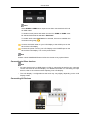
D.MENU button
Opens the on-screen D.MENU.
Note
The D.MENU button is activated when a TV tuner is connected and otherwise, the PIP button is enabled.
PIP button
Push the PIP button to turn the PIP screen On / Off.
Power button [
]
Use this button for turning the LCD Display on and off.
Introduction
Power indicator
Shows PowerSaver mode by blinking green.
Note
See PowerSaver described in the manual for further information regarding
power saving functions. For energy conservation, turn your LCD Display
OFF when it is not needed or when leaving it unattended for long periods.
Remote Control Sensor
Aim the remote control towards this spot on the LCD Display.
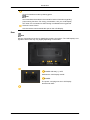
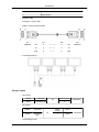
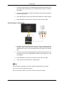
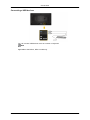
Rear
Note
See the "Connections" section for details about cable connections. The LCD Display's configuration at the back may vary slightly depending on the model.
POWER S/W ON [ I ] / OFF
Switches the LCD Display On/Off.
POWER
The power cord plugs into the LCD Display
and the wall outlet.
Introduction
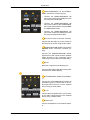
RGB/COMPONENT IN (PC/COMPONENT Connection Terminal (Input))
•
Connect the [RGB/COMPONENT IN]
port on the monitor to the RGB port on the
PC using the D-SUB cable.
•
Connect the [RGB/COMPONENT IN]
port on the monitor to the COMPONENT
port on the external device using the RGB
to COMPONENT cable.
•
Connect the [RGB/COMPONENT IN]
port on the monitor to the BNC port on the
PC using the RGB to BNC cable.
DVI IN (PC Video Connection Terminal)
Connect the [DVI IN] port on the monitor to
the DVI port on the PC using the DVI cable.
RGB/DVI/DP/HDMI AUDIO IN (PC/DVI/
DP/HDMI Audio Connection Terminal (Input))
Connect the [RGB/DVI/DP/HDMI AUDIO
IN] terminal of the monitor and the speaker
output terminal of your computer's sound
card using a stereo cable (sold separately).
DP IN
Receives a signal from the Display port.
Connect a DP cable to [DP IN] on the product
and DP IN on another display.
AV/COMPONENT AUDIO IN (R-AUDIOL)
Connect the [AV/COMPONENT AUDIO IN
(R-AUDIO-L)] port on the monitor to the audio output port on the PC or on the external
device using an audio cable.
AV IN
Connect the [AV IN] terminal of your monitor
to the video output terminal of the external
device using a VIDEO cable.
AUDIO OUT
Connect a headphone or an External speaker.
Introduction
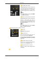
DC OUT
Make sure to use connecting [DC OUT] terminal to the authorized TV-Tuner Box
[SBB_DTC/ZA].
Otherwise, this may result in damage
to the product.
HDMI IN 1
•
Connect the [HDMI IN 1] terminal at the
back of your LCD Display to the HDMI
terminal of your digital output device using a HDMI cable.
•
Up to HDMI 1.3 can be supported.
Note
•
A normal external device (DVD player or
camcorder, etc.) or a TV tuner box can be
connected to the [HDMI IN 1] terminal.
•
To use a TV tuner box, make sure to connect it to the [HDMI IN 1] terminal.
HDMI IN 2 (MAGICINFO)
•
Connect the [HDMI IN 2 (MAGICINFO)]
terminal at the back of your LCD Display
to the HDMI terminal of your digital output
device using a HDMI cable.
•
Up to HDMI 1.3 can be supported.
Note
Using MagicInfo
•
To use MagicInfo with an MXN-3, MPN-3 model,
connect the MagicInfo output on the already included network box to [HDMI IN
2 (MAGICINFO)] on the product.
•
To use MagicInfo with an MX-3,MP-3 model,
install inside the product a network box
specified by Samsung and connect the
MagicInfo output on the network box to
[HDMI IN 2 (MAGICINFO)] on the product.
Introduction
RJ 45 MDC (MDC PORT)
MDC(Multiple Display Control) Program Port
Connect the LAN cable to [RJ45 MDC] on the
product and LAN on the PC. To use an MDC,
the MDC Program must be installed on the
PC.
Note
Go to Multi Control and select RJ45 MDC
as the MDC Connection.
RS232C OUT/IN (RS232C Serial PORT)
MDC(Multiple Display Control) Program Port
Connect a serial cable (cross type) to
[RS232C] on the product and RS232C on the
PC. To use an MDC, the MDC Program must
be installed on the PC.
Note
Go to Multi Control and select RS232C
MDC as the MDC Connection.
Applicable to the MXn-3, MPN-3 model only
RGB OUT
MagicInfo video output port
MAGICINFO OUT
This is the output terminal for the video, audio, and control signals of MagicInfo.
It can be used by connecting it to the [HDMI
IN 2 (MAGICINFO)] terminal using a DP to
HDMI cable.
LAN (LAN Connection Terminal)
Connects to a LAN cable to allow Internet or
network access in MagicInfo mode.
USB (USB Connection Terminal)
Keyboard / Mouse, Mass Storage Device
Compatible.
Introduction
Kensington Lock slot
A Kensington Lock is an anti-theft device that
enables users to lock the product so that they
can safely use it in public locations. Since the
shape and usage of the locking device may
differ depending on the model and the manufacturer, for more information, refer to the
User Manual supplied with the locking device
for more information.
Note
You must purchase the Kensington Lock
separately.
To lock the product, follow these
steps:
1.
Wrap the Kensington lock cable around
a large, stationary object such as a desk
or chair.
2.
Slide the end of the cable with the lock
attached through the looped end of the
Kensington lock cable.
3.
Insert the Kensington Lock into the security slot (
play.
4.
) on the back of the dis-
Lock the lock (
).
Note
•
These are general instructions. For exact
instructions, see the User Manual supplied with the locking device.
•
You can purchase the locking device
from an electronics store, an online shop,
or our service Center.
Note
The power switches of both of the monitor and the network box must be turned on for the
network box to operate normally.
Remote Control
Note
The performance of the remote control may be affected by a TV or other electronic device
operating near the LCD Display, causing a malfunction due to interference with the frequency.
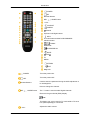
Introduction
POWER
OFF
Number Buttons
DEL
/ GUIDE button
+ VOL SOURCE
D.MENU
TOOLS
Up-Down Left-Right buttons
INFO
The Color button and the PC/DVI/HDMI/DP
selection button.
TTX/MIX
MTS/DUAL
ENTER/PRE-CH
MUTE
CH/P
TV
MENU
RETURN
EXIT
MagicInfo
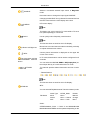
POWER
Turns the product On.
Turns the product Off.
OFF
Number Buttons
Used to enter the password during the OSD adjustment or
to use MagicInfo.
Press to change the channel.
DEL
/ GUIDE button
The "-" button is used to select Digital channels.
Electronic Program Guide (EPG) display.
Note
This button can only be used in TV mode while a TV tuner
box (sold separately) is connected.
+ VOL -
Adjusts the audio volume.
Introduction
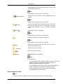
SOURCE
Selects a connected external input source or MagicInfo
mode.
Press the button to change the input signal SOURCE.
Changing the SOURCE is only allowed for external devices
that are connected to the LCD Display at the time.
D.MENU
DTV menu display
Note
This button can only be used in TV mode while a TV tuner
box (sold separately) is connected.
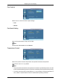
TOOLS
Use to quickly select frequently used functions.
Note
This function does not work for this LCD Display.
Up-Down Left-Right buttons
INFO
The Color button and the
PC/DVI/HDMI/DP selection
button.
TTX/MIX
Moves from one menu item to another horizontally, vertically
or adjusts selected menu values.
Current picture information is displayed on the upper left
corner of the screen.
In TV mode, these buttons can be used to configure a list of
channels.
You can select the PC, DVI, HDMI or DP(DisplayPort) external input directly in a mode other than TV mode.
TV channels provide written information services via teletext.
- Teletext Buttons
Note
This function does not work for this LCD Display.
MTS/DUAL
MTSYou can select MTS (Multichannel Television Stereo) mode.
FM Stereo
Audio Type
MTS/S_Mode
Default
Mono
Mono
Stereo
Mono ↔ Stereo
Manual
Change
SAP
Mono ↔ SAP
Mono
DUALSTEREO/MONO, DUAL l / DUAL ll and MONO/NICAM
MONO/NICAM STEREO can be operated depending on the
Introduction
broadcasting type by using the DUAL button on the remote
control while watching TV.
Note
Enabled when a TV tuner box is connected.
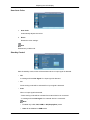
ENTER/PRE-CH
This button is used to return to the immediately previous
channel.
Note
Enabled when a TV tuner box is connected.
MUTE
CH/P
Pauses (mutes) the audio output temporarily. This is displayed on the lower left corner of the screen. The audio
comes back on if MUTE or - VOL + is pressed in the Mute
mode.
In TV mode, selects TV channels.
Note
Enabled when a TV tuner box is connected.
Allows you to watch an analogue or digital TV.
TV
Note
Enabled when a TV tuner box is connected.
MENU
RETURN
EXIT
MagicInfo
Opens the on-screen menu and exits from the menu or
closes the adjustment menu.
Returns to the previous menu.
Exits from the menu screen.
MagicInfo Quick Launch button.
Note
Using MagicInfo
•
To use MagicInfo with an MXN-3, MPN-3 model, connect the
MagicInfo output on the already included network box to
[HDMI IN 2 (MAGICINFO)] on the product.
•
To use MagicInfo with an MX-3, MP-3 model, install inside the
product a network box specified by Samsung and connect the MagicInfo output on the network box to[HDMI
IN 2 (MAGICINFO)] on the product.
User Installation Guide
Note
•
Be sure to call an installation expert of Samsung Electronics to install the product.
Introduction
•
The warranty becomes invalid if the product is installed by someone other than a professional authorized by Samsung Electronics.
•
A Samsung Electronics service center can provide details.
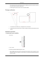
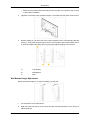
Tilt Angle and Rotation
2
1
1.
The product can be tilted up to 15 degrees from a vertical wall.
2.
To use the product in portrait mode, rotate it clockwise so that the LED indicator is at the
bottom.
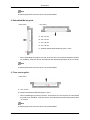
Ventilation requirement
1. Vertical wall mount condition
<Side view>
A : min. 40 mm
B: Ambient temperature Measuring point <35°C
•
When installing the product onto a vertical wall, be sure there is a 40 mm space or more
behind the product for ventilation, as shown above, and maintain the ambient temperature
at 35°C or lower.
Introduction
Note
A Samsung Electronics service center can provide details.
2. Embedded Mount guide
<Side view>
<Top view>
A : min. 40 mm
B : min. 70 mm
C : min. 50 mm
D : min. 50 mm
E : Ambient temperature Measuring point < 35°C
•
When embedding the product in a wall, be sure there is some space behind the product
for ventilation, as shown above, and maintain the ambient temperature at 35°C or lower.
Note
A Samsung Electronics service center can provide details.
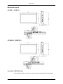
3. Floor mount guide
<Side view>
A : min. 50 mm
B: Ambient temperature Measuring point < 20°C
•
When embedding the product in the floor, be sure there is a 50 mm space or more behind
the product for ventilation, as shown above, and maintain the ambient temperature at 20
°C or lower.
Note
A Samsung Electronics service center can provide details.
Introduction
Mechanical Layout
(320MX-3, 320MP-3)
(320MXN-3, 320MPN-3)
Installation VESA Bracket
•
When installing VESA, make sure to comply with the international VESA standards.
Introduction
•
Purchasing VESA Bracket and Installation Information : Please contact your nearest
SAMSUNG Distributor to place an order. After your order is placed, installation professionals will visit you and install the bracket.
•
At least 2 persons are needed in order to move the LCD Display.
•
SAMSUNG is not responsible for any product damage or any injury caused by installation
at customer's discretion.
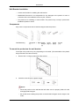
Dimensions
Notice
For securing the bracket on a wall, use only machine screws of 6 mm diameter and 8 to 12
mm length.
Accessories (sold separately)
•
Dimension with other accessories
Introduction
Wall Bracket Installation
•
Contact a technician for installing the wall bracket.
•
SAMSUNG Electronics is not responsible for any damages to the product or harm to
customers when the installation is done by the customer.
•
This product is for installing on cement walls. The product may not stay in place when
installed on plaster or wood.
Components
Only use the components and accessories shipped with the product.
Wall Bracket(1)
Hinge(Left 1, Right Plastic Screw
1)
Hanger (A)(11)
(4)
Screw
(B)(4)
Anchor
(11)
To mount the product on the wall bracket
The shape of the product may vary depending on the model. (The assemblies of the plastic
hanger and the screw are the same)
1.
Remove the 4 screws on the back of the product.
2.
Insert the screw B into the plastic hanger.
Notice
•
Mount the product on the wall bracket and make sure it is properly fixed to the left
and right plastic hangers.
•
Be careful when installing the product on the bracket as fingers can be caught in the
holes.
Introduction
•
Make sure the wall bracket is securely fixed to the wall, or the product may not stay
in place after installation.
3.
Tighten the 4 screws in step 2 (plastic hanger + screw B)to the rear holes of the product.
4.
Remove safety pin (3) and insert the 4 product holders into the corresponding bracket
holes (1). Then place the product(2) so that it is firmly fixed to the bracket. Make sure to
re-insert and tighten the safety pin (3) to securely hold the product to the bracket.
A-
LCD Display
B-
Wall Bracket
C-
Wall
Wall Bracket Angle Adjustment
Adjust the bracket angle to -2° before installing it on the wall.
1.
Fix the product to the wall bracket.
2.
Hold the product at the top in the center and pull it forward (direction of the arrow) to
adjust the angle.
Introduction
Note
You can adjust the bracket angle between -2° and 15°.
Make sure to use the top center, and not the left or the right side of the product to adjust the
angle.
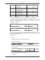
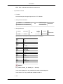
Remote Control (RS232C)
Cable connections
interface
RS232C(9 pin)
pin
TxD(No.2) RxD(No.3) GND(No.5)
Bits rate
9600 bps
Data Bits
8 bit
Parity
None
Stop Bits
1 bit
Flow control
None
Maximum length
15 m (only shielded type)
•
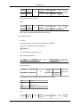
Pin assignment
Pin
Signal
1
Data Carrier Detect
2
Received Data
3
Transmitted Data
4
Data Terminal Ready
5
Signal Ground
6
Data Set Ready
7
Request to Send
Introduction
•
8
Clear to Send
9
Ring Indicator
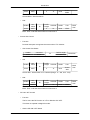
RS232C cable
Connector : 9-pin D-Sub
Cable : Cross (reversed) cable
-P1FEMALE
•
-P1-
-P2-
-P2-
Rx
2
--------->
3
Rx
Tx
3
<---------
2
Tx
Gnd
5
----------
5
Gnd
FEMALE
Connecting method
Control codes
•
•
•
Get control
Header
command
0xAA
command type
DATA Length
ID
0
CheckSum
Set control
Header
command
0xAA
command
type
commanding words
ID
DATA
Length
DATA
1
Value
CheckSum
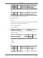
Introduction
No.
command type
command
Value range
1
Power control
0x11
0~1
2
Volume control
0x12
0~100
3
Input source control
0x14
-
4
Screen Mode control
0x18
-
5
Screen Size control
0x19
0~255
6
PIP on/off control
0x3C
0~1
7
Auto adjustment control
0x3D
0
8
Video wall Mode control
0x5C
0~1
9
Safety Lock
0x5D
0~1
- ID should show hexadecimal value of assigned ID, but ID 0 should be 0xFF.
- Every communication will be made in hexadecimals and Checksum is the sum of all
remainings. If it exceeds two digits,for example, it is 11+FF+01+01=112, discard the
number in the first digit like below.
example)PowerOn&ID=0
Header
command
0xAA
0x11
Header
command
ID
ID
0xAA
DATA
Length
DATA 1
1
Power
DATA
Length
DATA 1
1
1
0x11
CheckSum
12
If you want to control every mechanism connected with Serial Cable regardless of its ID,
set ID part to "0xFE" and send commands. At the time, each product will follow commands
but it will not respond with ACK.
•
Power Control
•
Function
Personal Computer turns TV / Monitor power ON/OFF.
•
•
Get Power ON/OFF Status
Header
command
0xAA
0x11
DATA Length
ID
0
CheckSum
Set Power ON/OFF
Header
command
ID
0xAA
DATA
Length
DATA
1
Power
0x11
Power : Power code to be set on TV / Monitor
1 : Power ON
CheckSum
Introduction
0 : Power OFF
•
Ack
Header
command
0xAA
0xFF
ID
DATA
Length
Ack/Nak
r-CMD
Val1
3
‘A’
0x11
Power
DATA
Length
Ack/Nak
r-CMD
Val1
3
‘N’
0x11
ERR
Check
Sum
Power : Same as above
•
Nak
Header
command
0xAA
0xFF
ID
Check
Sum
ERR : Error code that shows what occurred error is
•
Volume Control
•
Function
Personal Computer changes volume of TV / Monitor.
•
•
Get Volume Status
Header
command
0xAA
0x12
DATA Length
ID
CheckSum
0
Set Volume
Header
command
0xAA
0x12
ID
DATA
Length
DATA
1
Volume
CheckSum
Volume : Volume value code to be set on TV / Monitor (0 ~ 100)
•
Ack
Header
command
0xAA
0xFF
ID
DATA
Length
Ack/Nak
r-CMD
Val1
3
‘A’
0x12
Volume
DATA
Length
Ack/Nak
r-CMD
Val1
3
‘N’
0x12
ERR
Check
Sum
Volume : Same as above
•
Nak
Header
command
0xAA
0xFF
ID
Check
Sum
Introduction
ERR : Error code that shows what occurred error is
•
Input Source Control
•
Function
Personal Computer changes input source of TV / Monitor.
•
•
Get Input Source Status
Header
command
0xAA
0x14
DATA Length
ID
0
CheckSum
Set Input Source
Header
command
ID
0xAA
0x14
DATA
Length
DATA
1
Input Source
CheckSum
Input Source : Input Source code to be set on TV / Monitor
0x14
PC
0x1E
BNC
0x18
DVI
0x0C
AV
0x04
S-Video
0x08
Component
0x20
MagicInfo
0x1F
DVI_VIDEO
0x30
RF(TV)
0x40
DTV
0x21
HDMI1
0x22
HDMI1_PC
0x23
HDMI2
0x24
HDMI2_PC
0x25
DisplayPort
Caution
DVI_VIDEO, HDMI1_PC, HDMI2_PC → Get Only
In the case of MagicInfo, only possible with models include MagicInfo
In the case of TV, only possible with models include TV.
•
Ack
Introduction
Header
0xAA
command
ID
0xFF
DATA
Length
Ack/Nak
r-CMD
Val1
3
‘A’
0x14
Input
Source
DATA
Length
Ack/Nak
r-CMD
Val1
3
‘N’
0x14
ERR
Check
Sum
Input Source : Same as above
•
Nak
Header
command
0xAA
0xFF
ID
Check
Sum
ERR : Error code that shows what occurred error is
•
Screen Mode Control
•
Function
Personal Computer changes "Screen Mode" of TV/Monitor.
Cannot be controlled when Video Wall is on.
Caution
Only works with models include TV.
•
•
Get Screen Mode Status
Header
command
0xAA
0x18
DATA Length
ID
CheckSum
0
Set Picture Size
Header
command
0xAA
0x18
ID
DATA
Length
DATA
1
Screen
Mode
CheckSum
Screen Mode : Screen Mode code to be set on TV / Monitor
•
0x01
16 : 9
0x04
Zoom
0x31
Wide Zoom
0x0B
4:3
Ack
Header
command
ID
DATA
Length
Ack/Nak
r-CMD
Val1
Check
Sum
Introduction
0xAA
0xFF
3
‘A’
0x18
Screen
Mode
DATA
Length
Ack/Nak
r-CMD
Val1
3
‘N’
0x18
ERR
Screen Mode : Same as above
•
Nak
Header
command
0xAA
0xFF
ID
Check
Sum
ERR : Error code that shows what occurred error is
•
Screen Size Control
•
Function
Personal Computer recognizes the screen size of TV / Monitor.
•
•
Get Screen Size Status
Header
command
0xAA
0x19
DATA Length
ID
0
CheckSum
Ack
Header
0xAA
command
ID
0xFF
DATA
Length
3
Ack/Nak
‘A’
r-CMD
Val1
0x19
Screen
Size
Check
Sum
Screen Size : Screen Size of TV / Monitor (Range : 0 ~ 255, Unit : Inch)
•
Nak
Header
command
0xAA
0xFF
ID
DATA
Length
Ack/Nak
r-CMD
Val1
3
‘N’
0x19
ERR
ERR : Error code that shows what occurred error is
•
PIP ON / OFF Control
•
Function
The PC turns the PIP function of a TV or Monitor ON / OFF.
This does not operate in MagicInfo mode.
•
Get the PIP ON / OFF Status
Check
Sum
Introduction
•
Header
command
0xAA
0x3C
DATA Length
ID
CheckSum
0
Set the PIP ON / OFF
Header
command
0xAA
0x3C
ID
DATA
Length
DATA
1
PIP
CheckSum
PIP : The PIP ON / OFF code to set for the TV or Monitor
1 : PIP ON
0 : PIP OFF
•
Ack
Header
command
0xAA
0xFF
ID
DATA
Length
Ack/Nak
r-CMD
Val1
3
‘A’
0x3C
PIP
DATA
Length
Ack/Nak
r-CMD
Val1
3
‘N’
0x3C
ERR
Check
Sum
PIP : Same as above
•
Nak
Header
command
0xAA
0xFF
ID
Check
Sum
ERR : Error code that shows what occurred error is
•
Auto Adjustment Control (PC, BNC Only)
•
Function
Personal Computer controls PC system screen automatically.
•
Get Auto Adjustment Status
None
•
Set Auto Adjustment
Header
command
0xAA
0x3D
Auto Adjustment : 0x00 (Always)
•
Ack
ID
DATA
Length
DATA
1
Auto Adjustment
CheckSum
Introduction
Ack/Nak
r-CMD
Val1
0xFF
3
‘A’
0x3D
Auto Adjustment
Header
command
DATA
Length
Ack/Nak
r-CMD
Val1
0xAA
0xFF
3
‘N’
0x3D
ERR
0xAA
•
command
DATA
Length
Header
ID
Check
Sum
Nak
ID
Check
Sum
ERR : Error code that shows what occurred error is
•
Video Wall Mode Control
•
Function
Personal Computer converts Video Wall Mode of TV / Monitor when Video Wall is ON.
Only works with TV / Monitor where Video Wall is on.
Does not operate in MagicInfo
•
•
Get Video Wall Mode
Header
command
0xAA
0x5C
DATA Length
ID
CheckSum
0
Set Video Wall Mode
Header
command
0xAA
0x5C
ID
DATA
Length
DATA
1
Video Wall
Mode
CheckSum
Video Wall Mode : Video Wall Mode code to be set on TV / Monitor
1 : Full
0 : Natural
•
Ack
Header
command
DATA
Length
Ack/Nak
r-CMD
Val1
0x5C
Video
Wall
Mode
ID
0xAA
0xFF
Video Wall Mode : same as above
3
‘A’
Check
Sum
Introduction
•
Nak
Header
command
0xAA
0xFF
ID
DATA
Length
Ack/Nak
r-CMD
Val1
3
‘N’
0x5C
ERR
Check
Sum
ERR : Error code that shows what occurred error is
•
Safety Lock
•
Function
Personal Computer turns Safety Lock function of TV / Monitor ON / OFF.
Can operate regardless of whether power is ON / OFF.
•
•
Get Safety Lock Status
Header
command
0xAA
0x5D
DATA Length
ID
CheckSum
0
Set Safety Lock Enable / Disable
Header
command
ID
0xAA
0x5D
DATA
Length
DATA
1
Safety Lock
CheckSum
Safety Lock : Lock code to be set on TV / Monitor
1 : ON
0 : OFF
•
Ack
Header
0xAA
command
ID
0xFF
DATA
Length
Ack/Nak
r-CMD
Val1
3
‘A’
0x5D
Safety
Lock
DATA
Length
Ack/Nak
r-CMD
Val1
0x5D
Safety
Lock
Check
Sum
Safety Lock : Same as above
•
Nak
Header
0xAA
command
0xFF
ID
3
‘N’
ERR : Error code that shows what occurred error is
Check
Sum
Connections
Connecting a Computer
There are several ways to connect the computer to the monitor. Choose
one from the following options.
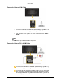
Using the D-sub (Analog) connector on the video card.
•
Connect the D-sub to the 15-pin, [RGB/COMPONENT IN] port on the
back of your LCD Display and the 15 pin D-sub Port on the computer.
Using the DVI (Digital) connector on the video card.
•
Connect the DVI Cable to the [DVI IN] port on the back of your LCD
Display and the DVI port on the computer.
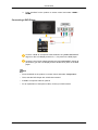
Using the D-sub (Digital) connector on the video card.
•
Connect the [HDMI IN 1] / [HDMI IN 2] port on the LCD Display to the
HDMI port on the PC using the HDMI cable.
Connections
Note
Select HDMI2 or HDMI1 as an input source when connected to the PC via
an HDMI cable.
To obtain normal picture and audio from the PC, HDMI2 or HDMI1 must
be selected before PC is selected in Edit Name.
To enable audio when DVI Device is selected, be sure to establish the
connection using step (
).
Connect the Audio cable for your LCD Display to the AUDIO port on the
back of the LCD Display.
Connect the power cord for your LCD Display to the POWER port on the
back of the LCD Display. Turn on the power switch.
Note
Contact a local SAMSUNG Electronics Service Center to buy optional items.
Connecting to Other devices
Note
•
AV input devices such as DVD players, VCRs or camcorders as well as your computer
can be connected to the LCD Display. For detailed information on connecting AV input
devices, refer to the contents under Adjusting Your LCD Display.
•
The LCD Display 's configuration at the back may vary slightly depending on the LCD
Display model.
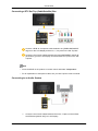
Connecting AV Devices
Connections
1.
Connect an audio cable to [AV/COMPONENT AUDIO IN (R-AUDIO-L)] on
the product and the audio port on an external device such as a VCR or
DVD player.
2.
Connect a video cable to [AV IN] on the product and the video output port
on the external device.
3.
Then, start the DVD, VCR or Camcorders with a DVD disc or tape inserted.
4.
Press SOURCE on the product or remote control and select "AV".
Connecting to a Camcorder
1.
Locate the AV output jacks on the camcorder. They are usually found on
the side or back of the camcorder. Connect a video cable between the
VIDEO OUTPUT jack on the camcorder and the [AV IN] on the LCD Display .
2.
Connect a set of audio cables between the AUDIO OUTPUT jacks on the
camcorder and the [AV /COMPONENT AUDIO IN (R-AUDIO-L)] on the
LCD Display .
3.
Press SOURCE on the product or remote control and select "AV".
4.
Then, start the Camcorders with a tape inserted.
Note
The audio-video cables shown here are usually included with a Camcorder.
(If not, check your local electronics store.)
If your camcorder is stereo, you need to connect a set of two cables.
Connections
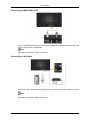
Connecting Using a HDMI Cable
1.
Connect an HDMI cable to [HDMI IN 2 (MAGICINFO)] or [HDMI IN 1] on
the product and the HDMI output port on a digital device.
2.
Press SOURCE on the product or remote control and select "HDMI1 /
HDMI2"
Note
In HDMI mode, only PCM format audio is supported.
Connecting Using a DVI to HDMI Cable
Connect a DVI-HDMI cable to [HDMI IN 2 (MAGICINFO)] or [HDMI IN 1]
and the DVI output port on the digital device.
Connect the red and white jacks of an RCA to stereo (for PC) cable to the
same colored audio output terminals of the digital output device, and connect the opposite jack to the [RGB/DVI/DP/HDMI AUDIO IN] terminal of
the LCD Display.
Connections
3.
Press SOURCE on the product or remote control and select "HDMI1 /
HDMI2"
Connecting a DVD Player
Connect a RGB to Component cable between the [RGB/COMPONENT
IN] port on the LCD Display and the PR, Y, PB jacks on the DVD player.
Connect a set of audio cables between the [AV/COMPONENT AUDIO IN
(R-AUDIO-L)] on the LCD Display and the AUDIO OUT jacks on the DVD
player.
Note
•
Press SOURCE on the product or remote control and select "Component".
•
Then, start the DVD Player with a DVD disc inserted.
•
A RGB to component cable is optional.
•
For an explanation of Component video, consult your DVD manual.
Connections
Connecting a DTV Set Top (Cable/Satellite) Box
Connect a RGB to Component cable between the [RGB/COMPONENT
IN] port on the LCD Display and the PR, Y, PB jacks on the Set Top Box.
Connect a set of audio cables between the [AV/COMPONENT AUDIO IN
(R-AUDIO-L)] on the LCD Display and the AUDIO OUT jacks on the Set
Top Box.
Note
•
Press SOURCE on the product or remote control and select "Component".
•
For an explanation of Component video, see your Set Top Box owner's manual.
Connecting to an Audio System
1.
Connect a set of audio cables between the AUX L, R jacks on the AUDIO
SYSTEM and [AUDIO OUT] on LCD Display.
Connections
Connecting to MAGICINFO OUT
Connect the [MAGICINFO OUT] terminal and the [HDMI IN 2 (MAGICINFO)] terminal on the
product using the DP to HDMI cable.
Note
Applicable to the MXn-3, MPN-3 model only.
Connecting a LAN Cable
Connect the LAN cable between the [LAN] port on the product and the [LAN] port on your
PC.
Note
Applicable to the MXn-3, MPN-3 model only.
Connections
Connecting a USB devices
You can connect USB devices such as a mouse or keyboard.
Note
Applicable to the MXn-3, MPn-3 model only.
Using the Software
Monitor Driver
Note
When prompted by the operating system for the monitor driver, insert the CDROM included with this monitor. Driver installation is slightly different from one
operating system to another. Follow the directions appropriate for the operating system you have.
Prepare a blank disk and download the driver Program file at the Internet web
site shown here.
Internet web site :
http://www.samsung.com/
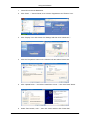
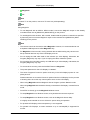
Installing the Monitor Driver (Automatic)
1.
Insert CD into the CD-ROM drive.
2.
Click "Windows".
3.
Choose your monitor model in the model list, then click the "OK" button.
4.
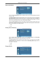
If you can see following message window, then click the "Continue Anyway" button. Then
click "OK" button (Microsoft® Windows® XP/2000 Operating System).
Using the Software
Note
This monitor driver is certified by Microsoft, and installing it will not damage your system.
The certified driver will be posted on Samsung Monitor homepage.
http://www.samsung.com/
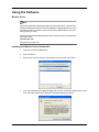
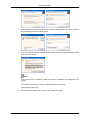
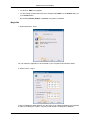
Installing the Monitor Driver (Manual)
Microsoft® Windows Vista™‚ Operating System
1.
Insert your Manual CD into your CD-ROM drive.
2.
(Start) and "Control Panel". Then, double-click on "Appearance and PersonalClick
ization".
3.
Click "Personalization" and then "Display Settings".
4.
Click "Advanced Settings...".
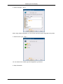
5.
Click "Properties" in the "Monitor" tab. If the "Properties" button is deactivated, it means
the configuration for your monitor is completed. The monitor can be used as is.
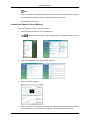
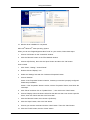
Using the Software
If the message "Windows needs..." is displayed, as shown in the figure below, click
"Continue".
Note
This monitor driver is under certifying MS logo, and this installation will not damage your
system.
The certified driver will be posted on Samsung Monitor homepage.
6.
Click "Update Driver..." in the "Driver" tab.
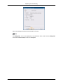
7.
Check the "Browse my computer for driver software" checkbox and click "Let me pick
from a list of device drivers on my computer".
8.
Click "Have Disk...” and select the folder (for example, D:\Drive) where the driver setup
file is located, and click "OK".
Using the Software
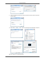
9.
Select the model that matches your monitor from the list of monitor models on the screen,
and click "Next".
10. Click "Close" → "Close" → "OK" → "OK" on the following screens displayed in sequence.
Microsoft® Windows® XP Operating System
Using the Software
1.
Insert CD into the CD-ROM drive.
2.
Click "Start" → "Control Panel", then click the "Appearance and Themes" icon.
3.
Click "Display" icon and choose the "Settings" tab then click "Advanced...".
4.
Click the "Properties" button on the "Monitor" tab and select "Driver" tab.
5.
Click "Update Driver..." and select "Install from a list or..." then click "Next" button.
6.
Select "Don't search, I will...", then click "Next" and then click "Have disk".
Using the Software
7.
Click the "Browse" button then choose A:(D:\Driver) and choose your monitor model in
the model list and click the "Next" button.
8.
If you can see the following message window, then click the "Continue Anyway" button.
Then click "OK" button.
Note
This monitor driver is certified by Microsoft, and this installation will not damage your
system.
The certified driver will be posted on Samsung Monitor homepage.
http://www.samsung.com/
9.
Click the "Close" button, then click the "OK" button continually.
Using the Software
10. Monitor driver installation is completed.
Microsoft® Windows® 2000 Operating System
When you can see "Digital Signature Not Found" on your monitor, follow these steps.
1.
Choose "OK" button on the "Insert disk" window.
2.
Click the "Browse" button on the "File Needed" window.
3.
Choose A:(D:\Driver), then click the "Open" button and then click "OK" button.
How to install
1.
Click "Start", "Setting", "Control Panel".
2.
Double click the "Display" icon.
3.
Select the "Settings" tab and click "Advanced Properties" button.
4.
Choose "Monitor".
Case1 : If the "Properties" button is inactive, it means your monitor is properly configured.
Please stop installation
Case2 : If the "Properties" button is active, click the "Properties" button, then follow the
next steps.
5.
Click "Driver" and then click on "Update Driver...", then click on the "Next" button.
6.
Choose "Display a list of the known drivers for this device so that I can choose a specific
driver", then click "Next" and then click "Have disk".
7.
Click the "Browse" button, then choose A:(D:\Driver).
8.
Click the "Open" button, then click "OK" button.
9.
Choose your monitor model and click the "Next" button. Then click "Next" button.
10. Click the "Finish" button, then the "Close" button.
Using the Software
If you can see the "Digital Signature Not Found" window, then click the "Yes" button.
Then click the "Finish" button and the "Close" button.
Microsoft® Windows® Millennium Operating System
1.
Click "Start", "Setting", "Control Panel".
2.
Double click the "Display" icon.
3.
Select the "Settings" tab and click "Advanced Properties" button.
4.
Select the "Monitor" tab.
5.
Click the "Change" button in the "Monitor Type" area.
6.
Choose "Specify the location of the driver".
7.
Choose "Display a list of all the driver in a specific location...", then click "Next" button.
8.
Click the "Have Disk" button.
9.
Specify A:\(D:\driver), then click "OK" button.
10. Select "Show all devices" and choose the monitor that corresponds to the one you connected to your computer and click "OK".
11. Continue choosing "Close" button and "OK" button until you close the Display Properties
dialogue box.
Microsoft® Windows® NT Operating System
1.
Click "Start", "Settings", "Control Panel", and then double-click "Display" icon.
2.
In Display Registration Information window, click Settings Tab and then click "All Display
Modes".
3.
Select a mode that you wish to use (Resolution, Number of Colors and Vertical frequency) and then click "OK".
4.
Click "Apply" button if you see the screen working normally after clicking "Test". If the
screen is not normal, change to a different mode (lower mode of resolution, Colors or
frequency).
Note
If there is no Mode at All Display Modes, select the level of resolution and vertical frequency
by referring to the Preset Timing Modes in the user guide.
Linux Operating System
To execute X-Window, you need to make the X86Config file, which is a type of system setting
file.
1.
Press "Enter" at the first and the second screen after executing the X86Config file.
2.
The third screen is for setting your mouse.
3.
Set a mouse for your computer.
4.
The next screen is for selecting a keyboard.
Using the Software
5.
Set a Keyboard for your computer.
6.
The next screen is for setting your monitor.
7.
First of all, set a horizontal frequency for your monitor. (You can enter the frequency
directly.)
8.
Set a vertical frequency for your monitor. (You can enter the frequency directly.)
9.
Enter the model name of your monitor. This information will not affect the actual execution
of X-Window.
10. You have finished setting up your monitor. Execute X-Window after setting other requested hardware.
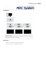
MDC (Multiple Display Control)
Installation
1.
Insert the installation CD into the CD-ROM drive.
2.
Click the MDC System installation Program.
Note
If the screen for installing the software does not appear, install it using the MDC System
execution file in the MDC folder of the CD-ROM.
3.
If the installation wizard screen does appear, click "Next."
4.
The "License Agreement" screen will appear. Click "Yes."
5.
The "Customer Information" window will appear. Register the user information and click
"Yes."
6.
The "Choose Destination Location" window will appear. Specify the file location to install
to and click "Next."
Note
If the file location is not specified, the Program will be installed in the default file location.
7.
The "Start Copying Files" window will appear. Confirm the file location and click "Next."
8.
The installation progress screen will appear.
9.
The "InstallShield Wizard Complete" screen will appear. Click "Finish."
Note
Select " Launch MDC System" and click "Finish." The MDC Program will immediately be
run.
Using the Software
10. If the installation is successfully completed, the quick MDC System execution icon will
appear on the desktop.
MDC execution icon may not appear depending on specification of computer system or monitor. If that happens, press F5 Key.
Installation Problems
The installation of MDC can be affected by such factors as the video card, motherboard and
the network environment.
Uninstall
The MDC Program can be removed only by using the "Add or Remove Programs" option of
the Windows® Control Panel.
Perform the following steps remove MDC.
Select "Setting/Control Panel" on the "Start" menu and then double-click "Add/Delete a Program".
Select MDC System from the list and then click the "Add/Delete" button.
Using Serial MDC
Using Ethernet MDC
S e r i a l MDC
Introduction
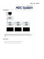
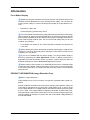
A Multiple Display Control (MDC) is an application allowing various displays to be easily and simultaneously
operated on a PC. RS-232C, a standard of serial communication, is used for the communication between a PC and
a display. Therefore, a serial cable should be connected between the serial port on a PC and the serial port on a
display.
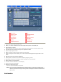
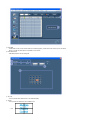
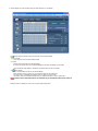
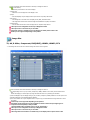
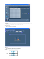
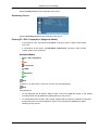
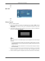
Main Screen
Click Start > Program > Samsung > MDC System to start the program.
Select a set to see the volume of the selected set within the slider.
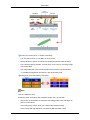
Main Icons
All
Remote control
Selection Buttons
Safety Lock
Refresh
Port Selection
Display Selection
Lamp Control
Info Grid
Option...
Control Tools
Dropdown Selectors
OSD Display
1.
Use the main icons to switch into each screen.
2.
Allows you to enable or disable the remote control signal receiving function of the display unit.
3.
Set the Safety Lock function.
When setting the Lock function, you can only operate power and lock buttons on the remote control and set.
4.
The setting for the PC Serial Port can change. The original value is COM1.
5.
Selects a Lamp adjustment mode.
6.
Adjusts the number of LFD IDs and the frequency of search repeats.
7.
Defines the range of LFD IDs to display. You can select or deselect the displayed IDs using the Select or Clear
button.
8.
All of the monitors can be selected or deselected.
9.
Selects (Select) or deselects (Clear) LFD IDs displayed by configuring 7 and 8.
10. This searches for monitors. The maximum number is indicated in the Max LFD Id field.
11. Select a display from Display Selection.
12. Use Grid to view brief information on selected display.
13. Use Control Tools to control displays.
14. Switches the OSD function On/Off.
- May not be supported depending on the product.
<Note> The remote control Enable/Disable function operates whether or not the power is On/Off, and this
applies to all displays connected to the MDC. However, regardless of the status at the time the MDC is
shut down, the remote control signal receiving function of all displays is initialized to Enable when the
MDC is closed.
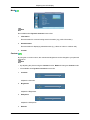
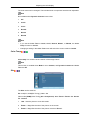
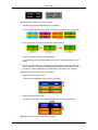
Port Selection
1. The Multiple Display Control is originally set to COM1.
2. If any port other than COM1 is used, COM1 through COM4 can be selected in the Port Selection Menu.
3. If the exact port name that is connected to the LCD Display using a serial cable is not selected, communication will
be unavailable.
4. The selected port is stored in the program and used for the next program as well.
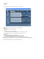
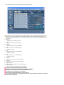
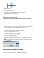
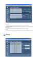
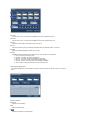
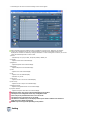
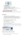
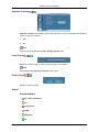
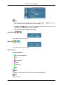
System
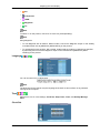
1. Click System in the main menu to open the system adjustment screen.
Info Grid shows some basic information necessary to System.
1)
(Power Status)
2) Input
3) Image Size
4) On Timer
5) Off Timer
2. Selects displays you want to adjust using the Select button or checkboxes.
System allows controlling some of the functions of the selected display.
1) Power On/Off
- Turns the power of the selected display On/Off.
2) Volume
- Controls the volume level of the selected display.
It receives the volume value of the selected display from the sets and displays it in the slider.
(If you deselect a single display or all displays, the default value 10 will be restored.)
3)
(Mute On/Off)
- Turns on/off the Mute function of the selected display.
When selecting one set at a time, turn on the Mute function for the selected set.
The Mute function is disabled automatically when you adjust the volume level.
(The values return to the default settings when you undo the selections or choose "Select All".)
The Volume Control and Mute features are available only for the displays whose power status is ON.
3. Selects whether to display the menu screen using the OSD Display menu.
1) Source OSD
- Sets whether the Source OSD will be displayed to indicate when the Source is changed.
2) Not Optimum Mode OSD
- Sets whether the Optimum Mode OSD will be displayed to indicate if the current mode is not supported.
3) No Signal OSD
- Sets whether the No Signal OSD will be displayed to indicate when there is no signal.
4) MDC OSD
- Sets whether the MDC OSD will be displayed to indicate when the settings are changed using the MDC.
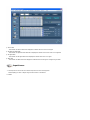
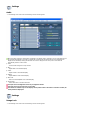
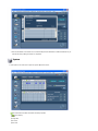
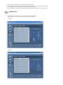
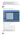
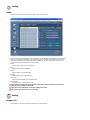
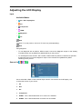
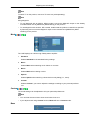
Input Source
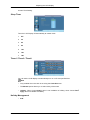
1. Click Input Source of the main icons and the Input Source control screen appears.
Selects displays you want to adjust using the Select button or checkboxes.
• TV Mode
• PC Mode
Info Grid shows some basic information necessary to Input Source Control.
1)
PC
- Changes the Input Source of the selected display to PC.
2)
BNC
- Changes the Input Source of the selected display to BNC.
3)
DVI
- Changes the Input Source of the selected display to DVI.
4)
TV
- Changes the Input Source of the selected display to TV.
5)
DTV
- Changes the Input Source of the selected display to DTV.
6)
AV
- Changes the Input Source of the selected display to AV.
7)
S-Video
- Changes the Input Source of the selected display to S-Video.
8)
Component
- Changes the Input Source of the selected display to Component.
9)
MagicInfo
- The Input source of MagicInfo works only on MagicInfo model.
10)
HDMI1/HDMI2
- Changes the Input Source of the selected display to HDMI.
11)
DP
- Switches the input source for the selected Display to DP.
12)
Channel
- Channel arrow appears when the Input Source is TV.
HDMI2 may not be supported depending on the product.
DP may not be supported depending on the product.
TV Source can be selected only in products with TV and controlling channels is allowed only when
Input Source is TV.
The Input Source Control feature is available only for the displays whose power status is ON.
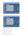
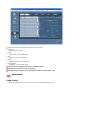
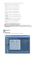
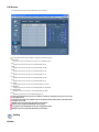
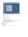
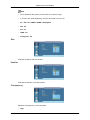
Image Size
PC, BNC, DVI, DP
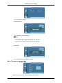
1. Click Image Size of the main icons and the Image Size control screen appears.
Info Grid shows some basic information necessary to Image Size Control.
1)
( Power Status)
- Shows the power status of the current display.
2) Image Size
- Shows the current Image Size of the display in use.
3) Input
- Info Grid displays only the displays whose Input Source is PC, BNC, DVI and DP.
4) PC Source
- Click Image Size in the main menu to display the PC, BNC, DVI and DP tabs.
- The Image Size Control button controls Image Size available for PC, BNC, DVI and DP.
5) Video Source
- Using the Image Size adjustment button, you can adjust the Image Size to a value available in the PC, BNC, DVI
and DP.
DP may not be supported depending on the product.
The Input source of MagicInfo works only on MagicInfo model.
The Input source of TV works only on TV model.
Image Size Control is available only for the displays for which power status is ON.
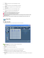
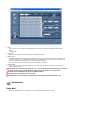
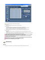
Image Size
TV, AV, S-Video, Component, DVI(HDCP), HDMI1, HDMI2, DTV.
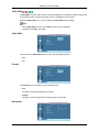
1. Click Image Size of the main icons and the Image Size control screen appears.
Info Grid shows some basic information necessary to Image Size Control.
1) To adjust Image Size in TV, AV, S-Video, Component, HDMI1, HDMI2 or DTV mode, click the Video Source tab.
Select the display you want to adjust by using the Select button or by checking the checkbox.
2) Info Grid displays only the display having TV, AV, S-Video, Component, HDMI1, HDMI2 or DTV as input source.
3) Switch Image Size of the selected display randomly.
4) The screen modes can only be adjusted when a TV (PAL only) is connected and the Image Size item is set to Auto
Wide.
HDMI2 may not be supported depending on the product.
Custom may not be supported depending on the product.
Auto Wide, Zoom1 and Zoom2 are not available for selection when the input signal type for Component
and DVI (HDCP) is 720p or 1080i.
(The Auto Wide mode is available only for TV, AV, and S-Video.)
The Input source of MagicInfo works only on MagicInfo model.
The Input source of TV works only on TV model.
The Image Size Control feature is available only for the displays whose power status is ON.
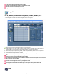
Time
1. Click Time of the main icons and the Time Control screen appears.
Info Grid shows some basic information necessary to Time Control.
1) Set clock
- Set the current time for the selected display (PC Time).
- To change the current time, first change the PC Time.
2) Timer
- Sets up Timer1, Timer2, Timer3 and Holiday Management.
3) Shows whether Timer is activated.
The Input source of MagicInfo works only on MagicInfo model.
The Input source of TV works only on TV model.
Time Control is available only for the displays for which the power status is ON.
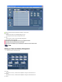
Time
Setting up Timer and Holiday Management
1. 1. Setting up Timer1, Timer2 and Timer3
1) On Time
- Sets the time in hours, in minutes and as AM/PM for turning the selected monitor on.
2) Off Time
- Sets the time in hours, in minutes and as AM/PM for turning the selected monitor off.
3) Volume
- Selects the volume when the selected monitor is turned on.
4) Source
- Selects the external input source that will be displayed when the selected monitor is turned on.
5) Holiday
- Applies the Holiday Management function to the Timer.
6) Repeat
- Available selections include Once, EveryDay, Mon~Fri, Mon~Sat, Sat~Sun, and Manual.
z
z
z
z
z
z
Once : The Timer goes off only once.
EveryDay : EveryDay: The Timer repeats daily.
Mon~Fri : The Timer repeats from Monday through Friday.
Mon~Sat : The Timer repeats from Monday through Saturday.
Sat~Sun : Sat~Sun: The Timer goes off on Saturday and Sunday.
Manual : Select a day of the week you want the Timer to go off.
2. Setting Holiday Management
The Holiday Management function specifies the dates in which the monitor will not be turned on or off by the Timer.
1) Specifies the date.
2) Delete All
- Deletes all of the holidays.
3) Add
- Adds the specified date.
4)
- Deletes the schedule in the selected line.
The Holiday Management function can be turned on or off in the Timer setup menu.
The Input source of MagicInfo works only on MagicInfo model.
The Input source of TV works only on TV model.
Time Control is available only for the displays for which the power status is ON.
Only enabled for a TV when Source is set to TV in On Time mode.
Only enabled for a model with MagicInfo installed when Source is set to MagicInfo in On Time mode.
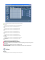
PIP
PIP Size
1. Click PIP of the main icons and the PIP control screen appears.
Selects displays you want to adjust using the Select button or checkboxes.
Info Grid shows some basic information necessary to PIP Size Control.
1) PIP Size
- Shows the current PIP Size of the display in use.
2) OFF
- Turns off the PIP of the selected display.
3) Large
- Turns on the PIP of the selected display and changes the size to Large.
4) Small
- Turns on the PIP of the selected display and changes the size to Small.
5) Double 1
- Turns on the PIP of the selected display and changes the size to Double 1.
6) Double 2
- Turns on the PIP of the selected display and changes the size to Double 2.
7) Double 3 (Picture By Picture)
- Turns on the PBP of the selected display and changes the size to Double 3.
The Input source of MagicInfo works only on MagicInfo model.
The Input source of TV works only on TV model.
PIP Size can be controlled with turning on the LCD Display power.
PIP
PIP Source
1. Click PIP of the main icons and the PIP control screen appears.
Info Grid shows some basic information necessary to PIP Source Control.
1) PIP Source
- PIP Source can be controlled with turning on the LCD Display power.
2) PC
- Changes the source of the PIP of the selected display to PC.
3) BNC
- Changes the source of the PIP of the selected display to BNC.
4) DVI
- Changes the source of the PIP of the selected display to DVI.
5) TV
- Changes the source of the PIP of the selected display to TV.
6) DTV
- Changes the source of the PIP of the selected display to DTV.
7) AV
- Changes the source of the PIP of the selected display to AV.
8) S-Video
- Changes the source of the PIP of the selected display to S-Video.
9) Component
- Changes the source of the PIP of the selected display to Component.
10) HDMI1/HDMI2
- Changes the source of the PIP of the selected display to HDMI.
11) DP
- Switches the PIP Source of the selected Display to DP.
HDMI2 may not be supported depending on the product.
DP may not be supported depending on the product.
Some of the PIP Sources may not be available for selection, depending on the input source type of the
Main Screen.
The Input source of MagicInfo works only on MagicInfo model.
The PIP Control feature is available only for the displays whose power status is ON and the PIP
function is set to ON.
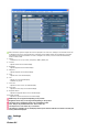
Settings
Picture
1. Click Settings of the main icons and the Settings Control screen appears.
Basic information required to adjust the Picture is displayed in the main menu. Settings for the selected monitor will
be displayed if one of the connected monitors is selected, and the default settings will be displayed if all monitors
are selected by clicking All and Select. If a value is changed in this screen, the current mode will automatically
switch to custom mode.
1) Picture
- Available only for TV, AV, S-Video, Component, HDMI1, HDMI2, DTV.
2) Contrast
- Adjusts Contrast of the selected display.
3) Brightness
- Adjusts Brightness of the selected display.
4) Sharpness
- Adjusts Sharpness of the selected display.
5) Color
- Adjusts Color of the selected display.
6) Tint
- Adjusts Tint of the selected display.
- Available only for NT.
7) Color Tone
- Adjusts the Color Tone for the selected display.
8) Color Temp
- Adjusts the Color Temp for the selected display.
9) Brightness Sensor
- Adjusts the Brightness Sensor for the selected display.
10) Dynamic Contrast
- Adjusts the Dynamic Contrast for the selected display.
HDMI2 may not be supported depending on the product.
Brightness Sensor may not be supported depending on the product.
The Input source of MagicInfo works only on MagicInfo model.
Color Temp is only enabled if the Color Tone is set to Off.
The Input source of TV works only on TV model.
This feature is available only for the displays whose power status is ON and if no selection is made, the
factory default is displayed.
Settings
Picture PC
1. Click Settings of the main icons and the Settings Control screen appears.
Basic information required to adjust settings is displayed. Settings for the corresponding SET will be imported and
displayed on the slider if a display ID is selected, and the default settings will be displayed if all display IDs are
selected by clicking All and Select. If a value is changed in this screen, the current mode will automatically switch to
custom mode.
1) Picture PC
- Available only for PC, BNC, DVI and DP.
2) Contrast
- Adjusts Contrast of the selected display.
3) Brightness
- Adjusts Brightness for the selected display.
4) Red
- Adjusts red Color of the selected display.
- Available only for NT.
5) Green
- Adjusts green Color of the selected display.
- Available only for NT.
6) Blue
- Adjusts blue Color of the selected display.
- Available only for NT.
7) Color Tone
- Adjusts the Color Tone for the selected display.
8) Color Temp
- Adjusts the Color Temp for the selected display.
9) Brightness Sensor
- Adjusts the Brightness Sensor for the selected display.
10) Dynamic Contrast
- Adjusts the Dynamic Contrast for the selected display.
DP may not be supported depending on the product.
Brightness Sensor may not be supported depending on the product.
The Input source of MagicInfo works only on MagicInfo model.
The Input source of TV works only on TV model.
Color Temp is only enabled if the Color Tone is set to Off.
This feature is available only for the displays whose power status is ON and if no selection is made, the
factory default is displayed.
Settings
Audio
1. Click Settings of the main icons and the Settings Control screen appears.
Basic information required to adjust Audio is displayed in the display window. Settings for the corresponding SET will
be imported and displayed on the slider if a display ID is selected, and the default settings will be displayed if all
display IDs are selected by clicking All and Select. If a value is changed in this screen, the current mode will
automatically switch to custom mode.
1) Audio
- Controls audio settings for all input sources.
2) Bass
- Adjusts Bass of the selected display.
3) Treble
- Adjusts Treble of the selected display.
4) Balance
- Adjusts Balance of the selected display.
5) SRS TS XT
- SRS TS XT Sound ON/OFF of the selected display.
6) Sound Select
- Select either Main or Sub when PIP is On.
The Input source of MagicInfo works only on MagicInfo model.
The Input source of TV works only on TV model.
This feature is available only for the displays whose power status is ON and if no selection is made, the
factory default is displayed.
Settings
Image Lock
1. Click Settings of the main icons and the Settings Control screen appears.
Info Grid shows some basic information necessary to Settings Control.
1) Image Lock
- Available only for PC, BNC.
2) Coarse
- Adjusts Coarse of the selected display.
3) Fine
- Adjusts Fine of the selected display.
4) Position
- Adjusts Position of the selected display.
5) Auto Adjustment
- Self-Adjust to the incoming PC signal.
The Input source of MagicInfo works only on MagicInfo model.
The Input source of TV works only on TV model.
Settings Control is available only for the displays for which the power status is ON.
Maintenance
Lamp Control
1. Click on the "Maintenance" icon in the Main Icon column to display the Maintenance screen.
An "Info Grid" showing several basic data items appears.
1) Maintenance
- Allows the Maintenance Control function for all input sources.
2) Lamp Control
- Automatically adjusts the backlight of the selected display at a specified time.
The Manual Lamp Control automatically turns off if you adjust using the Auto Lamp Control.
- Allows you to adjust the backlight of the selected display regardless of the time.
The Auto Lamp Control automatically turns off if you adjust using the Manual Lamp Control.
3) Ambient Light
- Detects the ambient light intensity at the designated monitor and automatically adjusts the picture brightness.
- You can specify a Reference value and designate a monitor that will automatically determine Lamp Value (the light
intensity from the lamp), based on the ambient light intensity.
Ambient Light is only supported for models that have a brightness sensor and is only enabled when
Ambient Brightness Mode is selected in the Lamp Control menu.
Auto Lamp Control and Manual Lamp Control are only enabled when User Control Mode is selected in
the Lamp Control menu.
The Maintenance Control feature is available only for the displays whose power status is ON.
The Input source of MagicInfo works only on MagicInfo model.
The Input source of TV works only on TV model.
Maintenance
Scroll
1. Click on the "Maintenance" icon in the Main Icon column to display the Maintenance screen.
1) Scroll
- This function is used to remove the afterimages that occur when a still screen is displayed on the selected
display
for a long time.
2) Pixel Shift
- This allows the screen to be moved finely at the specified time interval.
3) Safety Screen
- The Safety Screen function is used to prevent afterimages from occurring when a still screen is displayed on the
monitor for a long time. The Interval item is used to set the repetition cycle in hour units and the Time item is
used to set the time when the Safety Screen function must be performed.
The Type item can be set to Scroll, Pixel, Bar, Eraser, All White, or Pattern.
4) Safety Screen2
- This function is used to prevent afterimages from occurring. There are five (5) types that you can select and
control with this function.
For the Scroll type, the Time item can be set to 1, 2, 3, 4 or 5. For the Bar and Eraser types, it can be set
to 10, 20, 30, 40 or 50. For the All White and Pattern type, it can be set to 1, 5, 10, 20 or 30.
The Input source of MagicInfo works only on MagicInfo model.
The Input source of TV works only on TV model.
The Maintenance Control feature is available only for the displays whose power status is ON.
Maintenance
Video Wall
1. Click on the "Maintenance" icon in the Main Icon column to display the Maintenance screen.
1) Video Wall
- A Video Wall is a set of video screens that are connected together, so that each screen shows a part of the whole
picture or so that the same picture is repeated on each screen.
2) Video Wall Control
- Video Wall properties can be configured.
1) On / Off
- Turns on/off the Video Wall function of the selected display.
2) Format
- The format can be selected to see a divided screen.
z
Full
z
Natural
3) Video Wall (Screen divider)
- The screen can be divided into.
You can select a number of screens with a different layout when dividing.
z Select a mode from Screen divider.
z Select a display from Display Selection.
z The place will be set up by pressing a number in the selected mode.
z The maximum number of monitors that can be arranged: Horizontal X Vertical = 100
z Up to 15 monitors can be arranged in a row. The maximum value for Horizontal is 6 if Vertical is set to 15 while
the maximum value for Vertical is 6 if Horizontal is set to 15.
4) Viewing Screen Splits
- You can view and change the layout of screens using the Screen Divider settings.
The range of the Screen Divider setting may differ depending on the model.
You may not operate this function in MagicInfo.
The Input source of TV works only on TV model.
The Maintenance Control function is available only for the displays where the power status is ON.
Troubleshooting
1. The display you wish to control does not appear on the System Info Grid
- Check the connection of RS232C. (Check if it is properly connected to the Com1 port
- Check the displays to see if any of the other displays connected have the same ID. If more than one displays have
the same ID, those displays are not properly detected by the program due to data conflict.
- For monitors that support a Set ID between 0 to 99, you have to set the Set ID to a value between 0 and 99.
Note :
Check if the Set ID of the monitor is a value between 0 and 99 (set the value using the Display menu).
2. The display you wish to control does not appear on the other Control Info Grids
- Check to see if the display power is ON. (You can check this in System Info Grid)
- Check if you can change the input source of the display.
3. The dialogue box appears repeatedly.
- Check to see if the display you wish to control is selected.
4. Both On Timer and Off Timer have been set but different time is showing.
- Apply current time to synchronize the display clocks.
5. The remote may not function properly when you turn off the remote Function, disconnect the RS-232C cable, or exit
the program in an Irregular manner. Rerun the program and turn the remote function again to Restore normal
functions.
<Note> This program may malfunction due to problems in communication circuits or interference from electronic
appliances nearby.
Settings Value Display In Multiple Display Mode
When there are more than one displays connected, the settings values are displayed as follows.
1. No selection: Displays the Factory Default Value.
2. Selected one display: Fetches and displays the settings value for the selected display.
3. Selected one display (ID1) and add another display (ID3): The program, which was displaying the settings value of
ID 1, fetches and displays the value of ID3.
4. If all sets are selected at the same time by clicking All and Select, the default value will be restored.
E t h e r n e t MDC
Introduction
Unlike the previous method which used the serial data communication specifications RS-232C, an Ethernet
function has been added.
Connect the first display device and the PC by entering the IP address. To connect to another display device,
use an RS-232C serial cable. Refer to the figure above.
Main Screen
Click Start > Program > Samsung > MDC System to start the program.
Select a set to see the volume of the selected set within the slider.
Main Icons
Lamp Control
Add a Device
Display Selection
Remote Control
Info Grid
Safety Lock
Control Tools
Fault Device Alert
OSD Display
1.
Use the main icons to switch into each screen.
2.
You can add a device by entering the IP address configured on the monitor.
3.
Allows you to enable or disable the remote control signal receiving function of the display unit.
4.
Set the Safety Lock function.
When setting the Lock function, you can only operate power and lock buttons on the remote control and set.
5.
When connecting to the monitor fails, it turns the function that transfers the result through an email on or off.
6.
Selects a Lamp adjustment mode.
7.
Select a display from Display Selection.
8.
All of the monitors can be selected or deselected.
9.
Use Control Tools to control displays.
10. Switches the OSD function On/Off.
- May not be supported depending on the product.
<Note> The remote control Enable/Disable function operates whether or not the power is On/Off, and this
applies to all displays connected to the MDC. However, regardless of the status at the time the
MDC is shut down, the remote control signal receiving function of all displays is initialized to
Enable when the MDC is closed.
Add a Device
1. Enter the IP address of the monitor to be connected and press the Add button to add the IP address. If you
click the OK button, adding the monitor is completed.
System
1. Click System in the main menu to open the system adjustment screen.
Info Grid shows some basic information necessary to System.
1)
(Power Status)
2) Input
3) Image Size
4) On Timer
5) Off Timer
2. Selects displays you want to adjust using the Select All button or checkboxes.
System allows controlling some of the functions of the selected display.
1) Power On/Off
- Turns the power of the selected display On/Off.
2) Volume
- Controls the volume level of the selected display.
It receives the volume value of the selected display from the sets and displays it in the slider.
(If you deselect a single display or all displays, the default value 10 will be restored.)
3)
(Mute On/Off)
- Turns on/off the Mute function of the selected display.
When selecting one set at a time, turn on the Mute function for the selected set.
The Mute function is disabled automatically when you adjust the volume level.
(The values return to the default settings when you undo the selections or choose "Select All".)
The Volume Control and Mute features are available only for the displays whose power status is
ON.
3. Selects whether to display the menu screen using the OSD Display menu.
1) Source OSD
- Sets whether the Source OSD will be displayed to indicate when the Source is changed.
2) Not Optimum Mode OSD
- Sets whether the Optimum Mode OSD will be displayed to indicate if the current mode is not supported.
3) No Signal OSD
- Sets whether the No Signal OSD will be displayed to indicate when there is no signal.
4) MDC OSD
- Sets whether the MDC OSD will be displayed to indicate when the settings are changed using the MDC.
Network
1) Select or clear all the added devices; or refresh or delete selected devices.
2) The IP Address, ID (Ethernet or Serial), Mac Address and connection status of the connected monitor is displayed.
3) It can automatically check whether DHCP IP is set and then set the IP address.
4) It can automatically or manually set and then apply the IP Address, Subnet and Gateway of the selected monitor.
Input Source
1)
Click Input Source of the main icons and the Input Source control screen appears.
Selects displays you want to adjust using the Select All button or checkboxes.
• TV Mode
• PC Mode
Info Grid shows some basic information necessary to Input Source Control.
1) PC
- Changes the Input Source of the selected display to PC.
2) BNC
- Changes the Input Source of the selected display to BNC.
3) DVI
- Changes the Input Source of the selected display to DVI.
4) TV
- Changes the Input Source of the selected display to TV.
5) DTV
- Changes the Input Source of the selected display to DTV.
6) AV
- Changes the Input Source of the selected display to AV.
7) S-Video
- Changes the Input Source of the selected display to S-Video.
8) Component
- Changes the Input Source of the selected display to Component.
9) MagicInfo
- The Input source of MagicInfo works only on MagicInfo model.
10) HDMI1/HDMI2
- Changes the Input Source of the selected display to HDMI.
11) DP
- Switches the input source for the selected display to DP.
12) Channel
- Channel arrow appears when the Input Source is TV.
HDMI2 may not be supported depending on the product.
DP may not be supported depending on the product.
The Input Source Control feature is available only for the displays whose power status is ON.
TV Source can be selected only in products with TV and controlling channels is allowed only when
Input Source is TV.
Image Size
PC, BNC, DVI, DP
1. Click Image Size of the main icons and the Image Size control screen appears.
Info Grid shows some basic information necessary to Image Size Control.
1)
( Power Status)
- Shows the power status of the current display.
2) Image Size
- Shows the current Image Size of the display in use.
3) Input
- Info Grid displays only the displays whose Input Source is PC, BNC, DVI and DP.
4) PC Source
- Click Image Size in the main menu to display the PC, BNC, DVI and DP tabs.
- The Image Size Control button controls Image Size available for PC, BNC, DVI and DP.
5) Video Source
- Click the Video Source tab to control Image Size for respective Input Source.
The Input source of MagicInfo works only on MagicInfo model.
The Input source of TV works only on TV model.
Image Size Control is available only for the displays for which power status is ON.
DP may not be supported depending on the product.
Image Size
TV, AV, S-Video, Component, DVI(HDCP), HDMI1, HDMI2, DTV
1. Click Image Size of the main icons and the Image Size control screen appears.
Info Grid shows some basic information necessary to Image Size Control.
1) To adjust Image Size in TV, AV, S-Video, Component, HDMI1, HDMI2 or DTV mode, click the Video Source
tab.
Select the display you want to adjust by using the Select All button or by checking the checkbox.
2) Info Grid displays only the display having TV, AV, S-Video, Component, HDMI1, HDMI2 or DTV as input source.
3) Switch Image Size of the selected display randomly.
4) The screen modes can only be adjusted when a TV (PAL only) is connected and the Image Size item is set to
Auto Wide.
Custom may not be supported depending on the product.
Auto Wide, Zoom1 and Zoom2 are not available for selection when the input signal type for
Component and DVI (HDCP) is 720p or 1080i.
(The Auto Wide mode is available only for TV, AV, and S-Video.)
The Input source of MagicInfo works only on MagicInfo model.
The Input source of TV works only on TV model.
The Image Size Control feature is available only for the displays whose power status is ON.
HDMI2 may not be supported depending on the product.
Time
1. Click Time of the main icons and the Time Control screen appears.
Info Grid shows some basic information necessary to Time Control.
1) Clock Set
- Set the current time for the selected display (PC Time).
- To change the current time, first change the PC Time.
2) Timer
- Sets up Timer1, Timer2, Timer3 and Holiday Management.
3) Shows whether Timer is activated.
The Input source of MagicInfo works only on MagicInfo model.
The Input source of TV works only on TV model.
Time Control is available only for the displays for which the power status is ON.
Time
Setting up Timer and Holiday Management
1. Setting up Timer1, Timer2 and Timer3
1) On Time
- Sets the time in hours, in minutes and as AM/PM for turning the selected monitor on.
2) Off Time
- Sets the time in hours, in minutes and as AM/PM for turning the selected monitor off.
3) Volume
- Selects the volume when the selected monitor is turned on.
4) Source
- Selects the external input source that will be displayed when the selected monitor is turned on.
5) Holiday
- Applies the Holiday Management function to the Timer.
6) Repeat
- Available selections include Once, EveryDay, Mon~Fri, Mon~Sat, Sat~Sun, and Manual.
z
z
z
z
z
z
Once : The Timer goes off only once.
EveryDay : EveryDay: The Timer repeats daily.
Mon~Fri : The Timer repeats from Monday through Friday.
Mon~Sat : The Timer repeats from Monday through Saturday.
Sat~Sun : Sat~Sun: The Timer goes off on Saturday and Sunday.
Manual : Select a day of the week you want the Timer to go off.
2. Setting Holiday Management
The Holiday Management function specifies the dates in which the monitor will not be turned on or off by the
Timer.
1) Specifies the date.
2) Delete All
- Deletes all of the holidays.
3) Add
- Adds the specified date.
4)
- Deletes the schedule in the selected line.
The Holiday Management function can be turned on or off in the Timer setup menu.
The Input source of MagicInfo works only on MagicInfo model.
The Input source of TV works only on TV model.
Time Control is available only for the displays for which the power status is ON.
Only enabled for a TV when Source is set to TV in On Time mode.
Only enabled for a model with MagicInfo installed when Source is set to MagicInfo in On Time
mode.
PIP
PIP Size
1. Click PIP of the main icons and the PIP control screen appears.
Selects displays you want to adjust using the Select All button or checkboxes.
Info Grid shows some basic information necessary to PIP Size Control.
1) PIP Size
- Shows the current PIP Size of the display in use.
2) OFF
- Turns off the PIP of the selected display.
3) Large
- Turns on the PIP of the selected display and changes the size to Large.
4) Small
- Turns on the PIP of the selected display and changes the size to Small.
5) Double 1
- Turns on the PIP of the selected display and changes the size to Double 1.
6) Double 2
- Turns on the PIP of the selected display and changes the size to Double 2.
7) Double 3 (Picture By Picture)
- Turns on the PBP of the selected display and changes the size to Double 3.
PIP Size can be controlled with turning on the LCD Display power.
The Input source of TV works only on TV model.
The Input source of MagicInfo works only on MagicInfo model.
PIP
PIP Source
1. Click PIP of the main icons and the PIP control screen appears.
Info Grid shows some basic information necessary to PIP Source Control.
1) PIP Source
- PIP Source can be controlled with turning on the LCD Display power.
2) PC
- Changes the source of the PIP of the selected display to PC.
3) BNC
- Changes the source of the PIP of the selected display to BNC.
4) DVI
- Changes the source of the PIP of the selected display to DVI.
5) TV
- Changes the source of the PIP of the selected display to TV.
6) DTV
- Changes the source of the PIP of the selected display to DTV.
7) AV
- Changes the source of the PIP of the selected display to AV.
8) S-Video
- Changes the source of the PIP of the selected display to S-Video.
9) Component
- Changes the source of the PIP of the selected display to Component.
10) HDMI1/HDMI2
- Changes the source of the PIP of the selected display to HDMI.
11) DP
- Switches the PIP Source of the selected Display to DP.
Some of the PIP Sources may not be available for selection, depending on the input source type
of the Main Screen.
The PIP Control feature is available only for the displays whose power status is ON and the PIP
function is set to ON.
HDMI2 may not be supported depending on the product.
DP may not be supported depending on the product.
The Input source of MagicInfo works only on MagicInfo model.
HDMI2 may not be supported depending on the product.
Setting
Picture
1. Click Settings of the main icons and the Settings Control screen appears.
Basic information required to adjust the Picture is displayed in the main menu. Settings for the selected
monitor will be displayed if one of the connected monitors is selected, and the default settings will be
displayed if all monitors are selected by clicking All and Select. If a value is changed in this screen, the current
mode will automatically switch to custom mode.
1) Picture
- Available only for TV, AV, S-Video, Component, HDMI1, HDMI2, DTV.
2) Contrast
- Adjusts Contrast of the selected display.
3) Brightness
- Adjusts Brightness of the selected display.
4) Sharpness
- Adjusts Sharpness of the selected display.
5) Color
- Adjusts Color of the selected display.
6) Tint
- Adjusts Tint of the selected display.
- Available only for NT.
7) Color Tone
- Adjusts the Color Tone for the selected display.
8) Color Temp
- Adjusts the Color Temp for the selected display.
9) Brightness Sensor
- Adjusts the Brightness Sensor for the selected display.
10) Dynamic Contrast
- Adjusts the Dynamic Contrast for the selected display.
Brightness Sensor may not be supported depending on the product.
The Input source of MagicInfo works only on MagicInfo model.
Color Temp is only enabled if the Color Tone is set to Off.
The Input source of TV works only on TV model.
This feature is available only for the displays whose power status is ON and if no selection is
made, the factory default is displayed.
HDMI2 may not be supported depending on the product.
Setting
Picture PC
1. Click Settings of the main icons and the Settings Control screen appears.
Basic information required to adjust settings is displayed. Settings for the corresponding SET will be imported
and displayed on the slider if a display ID is selected, and the default settings will be displayed if all display IDs
are selected by clicking All and Select. If a value is changed in this screen, the current mode will automatically
switch to custom mode.
1) Picture PC
- Available only for PC, BNC, DVI and DP.
2) Contrast
- Adjusts Contrast of the selected display.
3) Brightness
- Adjusts Brightness for the selected display.
4) Red
- Adjusts red Color of the selected display.
- Available only for NT.
5) Green
- Adjusts green Color of the selected display.
- Available only for NT.
6) Blue
- Adjusts blue Color of the selected display.
- Available only for NT.
7) Color Tone
- Adjusts the Color Tone for the selected display.
8) Color Temp
- Adjusts the Color Temp for the selected display.
9) Brightness Sensor
- Adjusts the Brightness Sensor for the selected display.
10) Dynamic Contrast
- Adjusts the Dynamic Contrast for the selected display.
Brightness Sensor may not be supported depending on the product.
The Input source of MagicInfo works only on MagicInfo model.
The Input source of TV works only on TV model.
Color Temp is only enabled if the Color Tone is set to Off.
This feature is available only for the displays whose power status is ON and if no selection is
made, the factory default is displayed
DP may not be supported depending on the product.
Setting
Audio
1. Click Settings of the main icons and the Settings Control screen appears.
Basic information required to adjust Audio is displayed in the display window. Settings for the corresponding
SET will be imported and displayed on the slider if a display ID is selected, and the default settings will be
displayed if all display IDs are selected by clicking All and Select. If a value is changed in this screen, the
current mode will automatically switch to custom mode.
1) Audio
- Controls audio settings for all input sources.
2) Bass
- Adjusts Bass of the selected display.
3) Treble
- Adjusts Treble of the selected display.
4) Balance
- Adjusts Balance of the selected display.
5) SRS TS XT
- SRS TS XT Sound ON/OFF of the selected display.
6) Sound Select
- Select either Main or Sub when PIP is On.
This feature is available only for the displays whose power status is ON and if no selection is
made, the factory default is displayed.
The Input source of MagicInfo works only on MagicInfo model.
The Input source of TV works only on TV model.
Setting
Image Lock
1. Click Settings of the main icons and the Settings Control screen appears.
Info Grid shows some basic information necessary to Settings Control.
1) Image Lock
- Available only for PC, BNC.
2) Coarse
- Adjusts Coarse of the selected display.
3) Fine
- Adjusts Fine of the selected display.
4) Position
- Adjusts Position of the selected display.
5) Auto Adjustment
- Self-Adjust to the incoming PC signal.
The Maintenance Control feature is available only for the displays whose power status is ON.
The Input source of MagicInfo works only on MagicInfo model.
The Input source of TV works only on TV model.
Maintenance
Lamp Control
1. Click on the "Maintenance" icon in the Main Icon column to display the Maintenance screen.
An "Info Grid" showing several basic data items appears.
1) Maintenance
- Allows the Maintenance Control function for all input sources.
2) Lamp Control
- Automatically adjusts the backlight of the selected display at a specified time.
The Manual Lamp Control automatically turns off if you adjust using the Auto Lamp Control.
- Allows you to adjust the backlight of the selected display regardless of the time.
The Auto Lamp Control automatically turns off if you adjust using the Manual Lamp Control.
3) Ambient Light
- Detects the ambient light intensity at the designated monitor and automatically adjusts the picture
brightness.
- You can specify a Reference value and designate a monitor that will automatically determine Lamp Value
(the light intensity from the lamp), based on the ambient light intensity.
Ambient Light is only supported for models that have a brightness sensor and is only enabled
when Ambient Brightness Mode is selected in the Lamp Control menu.
Auto Lamp Control and Manual Lamp Control are only enabled when User Control Mode is
selected in the Lamp Control menu.
The Maintenance Control feature is available only for the displays whose power status is ON.
The Input source of MagicInfo works only on MagicInfo model.
The Input source of TV works only on TV model.
Maintenance
Scroll
1. Click on the "Maintenance" icon in the Main Icon column to display the Maintenance screen.
1) Scroll
- This function is used to remove the afterimages that occur when a still screen is displayed on the selected
display for a long time.
2) Pixel Shift
- This allows the screen to be moved finely at the specified time interval.
3) Safety Screen
- The Safety Screen function is used to prevent afterimages from occurring when a still screen is displayed on
the monitor for a long time. The Interval item is used to set the repetition cycle in hour units and the Time
item is used to set the time when the Safety Screen function must be performed.
The Type item can be set to Scroll, Pixel, Bar, Eraser, All White, or Pattern.
4) Safety Screen2
- This function is used to prevent afterimages from occurring. There are five (5) types that you can select and
control with this function.
For the Scroll type, the Time item can be set to 1, 2, 3, 4 or 5. For the Bar and Eraser types, it can be
set to 10, 20, 30, 40 or 50. For the All White and Pattern type, it can be set to 1, 5, 10, 20 or 30.
The Maintenance Control feature is available only for the displays whose power status is ON.
The Input source of MagicInfo works only on MagicInfo model.
The Input source of TV works only on TV model.
Maintenance
Video Wall
1. Click on the "Maintenance" icon in the Main Icon column to display the Maintenance screen.
1) Video Wall
- A Video Wall is a set of video screens that are connected together, so that each screen shows a part of the
whole picture or so that the same picture is repeated on each screen.
2) Video Wall Control
- Video Wall properties can be configured.
1) On / Off
- Turns on/off the Video Wall function of the selected display.
2) Format
- The format can be selected to see a divided screen.
z
Full
z
Natural
3) Video Wall (Screen divider)
- The screen can be divided into.
You can select a number of screens with a different layout when dividing.
z Select a mode from Screen divider.
z Select a display from Display Selection.
z The place will be set up by pressing a number in the selected mode.
z The maximum number of monitors that can be arranged: Horizontal X Vertical = 100
z Up to 15 monitors can be arranged in a row. The maximum value for Horizontal is 6 if Vertical is set to 15
while the maximum value for Vertical is 6 if Horizontal is set to 15.
4) Viewing Screen Splits
- You can view and change the layout of screens using the Screen Divider settings.
The range of the Screen Divider setting may differ depending on the model.
You may not operate this function in MagicInfo.
The Input source of TV works only on TV model.
The Maintenance Control function is available only for the displays where the power status is ON.
Troubleshooting
1. The display you wish to control does not appear on the System Info Grid
- Check if the entered IP address is correct and check the connection status of the Ethernet cable.
- Check the displays to see if any of the other displays connected have the same ID. If more than one displays
have the same ID, those displays are not properly detected by the program due to data conflict.
- For monitors that support a Set ID between 0 to 99, you have to set the Set ID to a value between 0 and 99.
Note :
Check if the Set ID of the monitor is a value between 0 and 99 (set the value using the Display
menu).
2. The display you wish to control does not appear on the other Control Info Grids
- Check to see if the display power is ON. (You can check this in System Info Grid)
- Check if you can change the input source of the display.
3. The dialogue box appears repeatedly.
- Check to see if the display you wish to control is selected.
4. Both On Timer and Off Timer have been set but different time is showing.
- Apply current time to synchronize the display clocks.
5. The remote may not function properly when you turn off the remote Function, disconnect the Ethernet cable, or
exit the program in an Irregular manner. Rerun the program and turn the remote function again to Restore normal
functions.
<Note> This program may malfunction due to problems in communication circuits or interference from electronic
appliances nearby.
Settings Value Display In Multiple Display Mode
When there are more than one displays connected, the settings values are displayed as follows.
1. No selection: Displays the Factory Default Value.
2. Selected one display: Fetches and displays the settings value for the selected display.
3. Selected one display (ID1) and add another display (ID3): The program, which was displaying the settings
value of ID 1, fetches and displays the value of ID3.
4. If all sets are selected at the same time by clicking All and Select, the default value will be restored.
Adjusting the LCD Display
Input
Available Modes
•
PC / DVI / DisplayPort
•
AV
•
Component
•
HDMI
•
MagicInfo
•
TV
Note
To watch TV on the product, connect a TV tuner box (sold separately).
Note
Using MagicInfo
•
To use MagicInfo with an MXN-3, MPN-3 model, connect the MagicInfo output on the already
included network box to [HDMI IN 2 (MAGICINFO)] on the product.
•
To use MagicInfo with an MX-3, MP-3 model, install inside the product a network box specified
by Samsung and connect the MagicInfo output on the network box to[HDMI IN 2 (MAGICINFO)] on the product.
Source List
Use to select PC, HDMI or other external input sources connected to the LCD Display. Use
to select the screen of your choice.
1.
PC
2.
DVI
3.
AV
4.
Component
5.
HDMI1 - This is deactivated when a TV tuner box is installed.
6.
HDMI2 - This is deactivated when a network box is installed.
Adjusting the LCD Display
7.
DisplayPort
8.
MagicInfo - A network box must be connected to use MagicInfo with a MX-3,MP-3
model.
9.
TV- Enabled if a TV tuner box is connected.
Note
The [RGB/COMPONENT IN] port is compatible with RGB (PC) and Component signals.
However, the picture may display abnormally if the connected external input signal is different
from the selected video signal.
PIP
Note
The PIP function is not available when Video Wall is On.
When external AV devices such as VCRs or DVDs are connected to the LCD Display , PIP
allows you to watch video from those devices in a small window super-imposed on the PC
Video signal. (Off/On)
Note
•
PIP turns off when the LCD Display is switched to an external source.
•
If you select
,
,
in Size, Position and Transparency will not be activated.
PIP
Turns the PIP Screen Off/On.
•
Off
•
On
Source
Selects the input source for the PIP.
Adjusting the LCD Display
Note
•
PIP is disabled if the primary screen does not receive a signal.
•
A TV tuner box (sold separately) must be connected to use the TV.
•
PC : DVI / AV / HDMI1 / HDMI2 / DisplayPort
•
DVI : PC
•
AV : PC
•
HDMI : PC
•
DisplayPort : PC
Size
Changes the Size of the PIP window.
Position
Changes the Position of the PIP window.
Transparency
Adjusts the Transparency of PIP windows.
•
High
Adjusting the LCD Display
•
Medium
•
Low
•
Opaque
Edit Name
Name the input device connected to the input jacks to make your input source selection
easier.
VCR / DVD / Cable STB / HD STB / Satellite STB / AV Receiver / DVD Receiver /
Game /Camcorder / DVD Combo / DHR / PC / DVI PC / DVI Devices
Note
•
The displayed devices differ depending on the external input mode.
•
When connecting a PC to the HDMI terminal, set Edit Name to PC. In other cases, set
Edit Name to AV. However, since 640x480, 720P (1280x720), and 1080p (1920x1080)
are common signals for AV and PC, make sure to set the Edit Name in accordance with
the input signal.
•
When a PC is connected, set Edit Name to DVI PC to enjoy the video and audio from the
connected PC.
•
When an AV device is connected, set Edit Name to DVI Device to enjoy the video and
audio from the connected AV device.
Source AutoSwitch Settings
Turning on the display with Source AutoSwitch On, and the previous video source selection
is not active, the display will automatically search the different video input sources for active
video.
Note
•
If the display TV source is active (TV tuner connected to the display) the Source AutoSwitch search function becomes inactive. The display will remain in the TV source.
•
Source AutoSwitch selection and PIP function: If the Source AutoSwitch selection is
set to On, the PIP function will not work, the Source AutoSwitch selection must be set
to Off, for the PIP feature to work.
•
When the Source AutoSwitch selection is On, and or the Primary Source Recovery is
On, the display power saving mode becomes inactive.
•
When Primary Source Recovery is On, only the Primary Source and Secondary
Source selection are available and they are interchangeable and selectable at will.
Refer to PIP > Source for compatible signals for each primary input source.
Adjusting the LCD Display
Source AutoSwitch
When the Source AutoSwitch is On, the display video source will automatically be searched
for active video.
The Primary Source selection will be activated, if the current video source is not recognized.
Secondary source selection will become active, if no primary video source is available. If
the primary or secondary source is not recognized, the display will search again, if no active
video is found the display will show the no-input-signal message.
When the Primary Source selection is set to All, the display will search all the video source
inputs twice in sequence looking for an active video source, returning back to the first video
source in the sequence if no video is found.
1.
Off
2.
On
Primary Source Recovery
When Primary Source Recovery is On, only the Primary Source and Secondary
Source video source selection will be searched for active video.
The Primary Source will be selected if active video is found, if no video is found, the Secondary Source will be selected, if no video is found in Secondary Source again, the noinput-signal is displayed.
1.
Off
2.
On
Primary Source
Adjusting the LCD Display
Specify Primary Source for the automatic input source.
Secondary Source
Specify Secondary Source for the automatic input source.
Picture [PC / DVI / DisplayPort / MagicInfo Mode]
•
If connected to a PC, set Edit Name to DVI PC, and enjoy video or audio content saved
on the PC.
•
If connected to an AV device, set Edit Name to DVI Device, and enjoy video or audio
content saved on the AV device.
Available Modes
•
PC / DVI / DisplayPort
•
AV
•
Component
•
HDMI
•
MagicInfo
•
TV
Note
To watch TV on the product, connect a TV tuner box (sold separately).
Note
Using MagicInfo
•
To use MagicInfo with an MXN-3, MPN-3 model, connect the MagicInfo output on the already
included network box to [HDMI IN 2 (MAGICINFO)] on the product.
•
To use MagicInfo with an MX-3, MP-3 model, install inside the product a network box specified
by Samsung and connect the MagicInfo output on the network box to[HDMI IN 2 (MAGICINFO)] on the product.
Adjusting the LCD Display
Mode
Note
Not available when Dynamic Contrast is set to On.
1.
Information
Recommended for communicating exact information (e.g. public information).
2.
Advertisement
Recommended for displaying advertisements (e.g. videos or indoor or outdoor ads).
3.
Custom
Custom
By using the on-screen menus, the contrast and brightness can be changed to your personal
preference.
Note
•
By adjusting the picture using the Custom function, Mode will change to Custom mode.
•
Not available when Dynamic Contrast is set to On.
1.
Contrast
Adjusts the Contrast.
2.
Brightness
Adjusts the Brightness.
3.
Sharpness
Adjusts the Sharpness.
4.
Gamma
Adjusting the LCD Display
Adjust the mid-range brightness (Gamma) for the picture.
•
Natural
•
Mode 1
Sets the picture brighter than Natural.
•
Mode 2
Sets the picture darker than Mode 1.
•
Mode 3
Increases the contrast between dark and bright colors.
Color Tone
Note
Not available when Dynamic Contrast is set to On.
The Color tones can be changed.
1.
Off
2.
Cool
3.
Normal
4.
Warm
5.
Custom
Note
If you set the Color Tone to Cool, Normal, Warm, or Custom, the Color Temp. function is
disabled.
If you set the Color Tone to Off, the Color Control function is disabled.
Adjusting the LCD Display
Color Control
Adjusts individual Red, Green, Blue Color balance.
Note
Not available when Dynamic Contrast is set to On.
1.
Red
2.
Green
3.
Blue
Color Temp.
Color Temp. is a measure of the 'warmth' of the image Colors.
Note
This function is enabled when Mode is set to Custom, and Dynamic Contrast and Color
Tone are Off.
Image Lock
Image Lock is used to fine-tune and get the best image by removing noise that creates
unstable images with jitters and shakiness. If satisfactory results are not obtained using the
Fine adjustment, use the Coarse adjustment and then use Fine again.
Note
Available in PC mode only.
Coarse
Removes noise such as vertical stripes. Coarse adjustment may move the screen image
area. You may relocate it to the Center using the horizontal control menu.
Fine
Removes noise such as horizontal stripes. If the noise persists even after Fine tuning, repeat
it after adjusting the frequency (clock speed).
Adjusting the LCD Display
Position
Adjusts the screen location horizontally and vertically.
Auto Adjustment
The values of Fine, Coarse, Position are adjusted automatically. By changing the resolution
in the control panel, the auto function is performed.
Note
Available in PC mode only.
Signal Balance
This is used to make up for the weak RGB signal transmitted by a long signal cable.
Note
•
Not available when Dynamic Contrast is set to On.
•
Available in PC mode only.
Signal Balance
Selects either On or Off with the signal balance.
Signal Control
Note
Available when Signal Balance is set to On.
1.
R-Gain
Adjusting the LCD Display
2.
G-Gain
3.
B-Gain
4.
R-Offset
5.
G-Offset
6.
B-Offset
Size
The Size can be switched.
1.
16:9
2.
4:3
PIP Picture
Adjusts the PIP Screen Settings.
Note
•
1.
Available Modes: PIP On
Contrast
Adjusts the Contrast of the PIP window on the screen.
2.
Brightness
Adjusting the LCD Display
Adjusts the Brightness of the PIP window on the screen.
3.
Sharpness
Adjusts the Sharpness of the PIP window on the screen.
4.
Color
Adjusts the Color of the PIP window on the screen.
Note
Only enabled when the PIP input source is HDMI.
5.
Tint
Adds a natural tone to the PIP window.
Note
The Tint slider is only displayed when PIP input source is HDMI or AV.
Dynamic Contrast
Dynamic Contrast automatically detects the distribution of the visual signal and adjusts to
create an optimum contrast.
1.
Off
2.
On
Note
This function is disabled when PIP or Energy Saving is On.
Lamp Control
Adjusts the inverter lamp in order to reduce energy consumption.
Note
Not available when Dynamic Contrast is set to On.
Adjusting the LCD Display
Picture Reset
Reset the screen settings.
Picture [ AV / HDMI / TV / Component Mode]
Available Modes
•
PC / DVI / DisplayPort
•
AV
•
Component
•
HDMI
•
MagicInfo
•
TV
Note
To watch TV on the product, connect a TV tuner box (sold separately).
Note
Using MagicInfo
•
To use MagicInfo with an MXN-3, MPN-3 model, connect the MagicInfo output on the already
included network box to [HDMI IN 2 (MAGICINFO)] on the product.
•
To use MagicInfo with an MX-3, MP-3 model, install inside the product a network box specified
by Samsung and connect the MagicInfo output on the network box to[HDMI IN 2 (MAGICINFO)] on the product.
Mode
The LCD Display has four automatic picture settings ("Dynamic", "Standard", "Movie" and
"Custom") that are preset at the factory.
Note
Not available when Dynamic Contrast is set to On.
1.
Dynamic
Adjusting the LCD Display
2.
Standard
3.
Movie
4.
Custom
Custom
By using the on-screen menus, the contrast and brightness can be changed to your personal
preference.
Note
Not available when Dynamic Contrast is set to On.
Contrast
Adjusts the Contrast.
Brightness
Adjusts the Brightness.
Sharpness
Adjusts the picture Sharpness.
Color
Adjusts the picture Color.
Tint
Adds a natural tone to the display.
Note
The Tint slider is only displayed when PIP input source is HDMI or AV.
Color Tone
Adjusting the LCD Display
The Color tones can be changed. The individual Color components are also user adjustable.
Note
Not available when Dynamic Contrast is set to On.
1.
Off
2.
Cool2
3.
Cool1
4.
Normal
5.
Warm1
6.
Warm2
Note
•
If you set the Color Tone to Cool2, Cool1, Normal, Warm1, or Warm2, the Color
Temp. function is disabled.
•
Changing a setting in the Color Tone menu will switch the screen mode to Custom.
Color Temp.
Color temp. is a measure of the 'warmth' of the image Colors.
Note
This function is enabled when Mode is set to Custom, and Dynamic Contrast and Color
Tone are Off.
Size
The Size can be switched.
PC mode(PC, HDMI[PC Timing ]): 16:9 - 4:3
Video mode (HDMI [Video Timing], AV or Component): 16:9 - Zoom1 - Zoom2 - 4:3 - Screen
Fit - Custom
1.
16:9 - Sets the picture to 16:9 wide mode.
2.
Zoom 1 - Magnifies the size of the picture on the screen.
3.
Zoom 2 - Magnifies the size of the picture more than Zoom 1.
Adjusting the LCD Display
4.
4:3 - Sets the picture to 4:3 normal mode.
5.
Screen Fit - Displays the input scenes as they are without any cutoff when HDMI 720p,
1080i, 1080p signals are input.
6.
Custom - Changes the resolution to suit the user's preferences.
Note
•
Certain external devices may feed the display an out of spec signal that may cause cutoff
even when using the Screen Fit feature.
•
Screen Fit is enabled for only 1080i/p in Component mode and for 1080i/p or 720p in
HDMI mode.
•
Zoom 1 and Zoom 2 are disabled for HD signals (1080i/p, 720p or 768p).
•
The Position and Reset functions are available in Zoom 1 or Zoom 2 modes.
Digital NR (Digital Noise Reduction)
Turns the Digital Noise Reduction feature Off/On. The Digital Noise Reduction feature allows
you to enjoy clearer and crisper images.
1.
Off
2.
On
Note
Digital NR function is not available for all resolutions.
HDMI Black Level
When a DVD or set-top box is connected to your TV via HDMI, it may cause a degradation
in the screen quality, such as an increase in the black level, a low contrast, or discoloration,
etc., depending on the external device connected. In this case, adjust the screen quality of
your TV by configuring the HDMI Black Level.
1.
Normal
Adjusting the LCD Display
2.
Low
Note
For Timing which can be used for both the PC and the DTV in HDMI mode, HDMI Black
Level will be activated.
Film Mode
Film Mode calibrates unnatural picture when watching a movie (24 frames) played on a TV
(30 frames).
Moving subtitles may appear corrupted when this mode is enabled.
(In HDMI mode, this function is available when the input signal is interlaced scan; it is not
available in progressive scan.)
1.
Off
2.
On
PIP Picture
Adjusts the PIP Screen Settings.
Note
Available Modes: PIP On
1.
Contrast
Adjusts the Contrast of the PIP window on the screen.
2.
Brightness
Adjusts the Brightness of the PIP window on the screen.
3.
Sharpness
Adjusts the Sharpness of the PIP window on the screen.
Adjusting the LCD Display
Dynamic Contrast
Dynamic Contrast automatically detects the distribution of the visual signal and adjusts to
create an optimum contrast.
1.
Off
2.
On
Note
This function is disabled when PIP or Energy Saving is On.
Lamp Control
Adjusts the inverter lamp in order to reduce energy consumption.
Note
Not available when Dynamic Contrast is set to On.
Picture Reset
Reset the screen settings.
Sound
Available Modes
•
PC / DVI / DisplayPort
•
AV
•
Component
•
HDMI
•
MagicInfo
•
TV
Adjusting the LCD Display
Note
To watch TV on the product, connect a TV tuner box (sold separately).
Note
Using MagicInfo
•
To use MagicInfo with an MXN-3, MPN-3 model, connect the MagicInfo output on the already
included network box to [HDMI IN 2 (MAGICINFO)] on the product.
•
To use MagicInfo with an MX-3, MP-3 model, install inside the product a network box specified
by Samsung and connect the MagicInfo output on the network box to[HDMI IN 2 (MAGICINFO)] on the product.
Mode
The LCD Display has a built-in high fidelity stereo amplifier.
1.
Standard
Selects Standard for the standard factory settings.
2.
Music
Selects Music when watching music videos or concerts.
3.
Movie
Selects Movie when viewing movies.
4.
Speech
Selects Speech when watching a show that is mostly dialog (i.e., news).
5.
Custom
Selects Custom if you want to adjust the settings according to your personal preferences.
Custom
The sound settings can be adjusted to suit your personal preferences.
Note
Bass
•
You can hear the sound even when sound value is set to 0.
•
If you adjust sound using Custom function, Mode will turn to Custom mode.
Adjusting the LCD Display
Emphasizes low frequency audio.
Treble
Emphasizes high frequency audio.
Balance
Allows you to Adjusts the sound balance between the left and right speakers.
Auto Volume
Reduces the difference in volume control between broadcasters.
1.
Off
2.
On
SRS TS XT
SRS TS XT is a patented SRS technology that solves the problem of playing 5.1 multichannel
content over two speakers. TruSurround XT delivers a compelling, virtual surround sound
experience through any two-speaker playback system, including internal television speakers.
It is fully compatible with all multichannel formats.
1.
Off
2.
On
Adjusting the LCD Display
Sound Select
Enable the sound of either the primary or secondary display in PIP mode.
Note
Available when PIP is set to On.
1.
Main
2.
Sub
Speaker Select
When you use the product with it connecting to a Home Theater, turn the internal speakers
off so you can listen to sound from the Home Theater's (external) speakers.
1.
Internal
Sound is outputted both from the Internal speaker and the External speakers, but the
volume control is only available from the Internal speaker.
2.
External
When sound is only outputted from the External speakers, the volume control is also
only available from the External speakers.
Sound Reset
Reset the sound settings.
Setup
Available Modes
•
PC / DVI / DisplayPort
Adjusting the LCD Display
•
AV
•
Component
•
HDMI
•
MagicInfo
•
TV
Note
To watch TV on the product, connect a TV tuner box (sold separately).
Note
Using MagicInfo
•
To use MagicInfo with an MXN-3, MPN-3 model, connect the MagicInfo output on the already
included network box to [HDMI IN 2 (MAGICINFO)] on the product.
•
To use MagicInfo with an MX-3, MP-3 model, install inside the product a network box specified
by Samsung and connect the MagicInfo output on the network box to[HDMI IN 2 (MAGICINFO)] on the product.
Language
You can choose one of 13 languages.
Note
The language chosen affects only the language of the OSD. It has no effect on any software
running on the computer.
Time
Selects from one of 4 time settings, Clock Set, Sleep Timer, Timer, and Holiday Management.
Clock Set
Adjusting the LCD Display
Current Time Setting.
Sleep Timer
Turns the LCD Display off automatically at certain times.
1.
Off
2.
30
3.
60
4.
90
5.
120
6.
150
7.
180
Timer1 / Timer2 / Timer3
You can set the LCD display to automatically turn on or off at a specified time.
Note
•
Only enabled when the clock is set using the Clock Set menu.
•
The Manual option allows you to select a day of the week.
•
Holiday : When choose Apply, timer is not available on holiday; when choose Don’t
apply, timer is available on holiday.
Holiday Management
•
Add
Adjusting the LCD Display
You can register holidays.
•
Delete Selected
You can delete selected holidays.
Note
•
•
Only enabled when registered holidays are selected.
•
More than one holiday can be selected and deleted.
Delete All
You can delete all the registered holidays.
Menu Transparency
Change the transparency of the background of the OSD.
Adjusting the LCD Display
1.
High
2.
Medium
3.
Low
4.
Opaque
Safety Lock
Change PIN
The password can be changed.
The preset password for the LCD Display is "0000".
Note
If you forgot your password, press the remote buttons INFO + EXIT + MUTE to reset the
password to "0000."
Lock
This is the function that locks the OSD in order to keep the current settings or to prevent
others from adjusting the settings.
Energy Saving
This feature adjusts the power consumption of the unit in order to save energy.
1.
Off
2.
On
Adjusting the LCD Display
Video Wall
A Video Wall is a set of video screens connected together, so that each screen shows a part
of the whole picture or where the same picture is repeated on each screen.
When the Video Wall is on, you can adjust the Video Wall screen setting.
Note
•
When Video Wall is running, the Size functions are not available.
•
Disabled when PIP is set to On.
Video Wall
Turns Off/On the Video Wall function of the selected display Off/On.
•
Off
•
On
Format
The Format can be selected to see a divided screen.
•
Full
Provides a full screen without any margins.
•
Natural
Displays a natural image with the original aspect ratio intact.
Horizontal
Adjusting the LCD Display
Sets how many parts the screen should be divided horizontally.
Fifteen adjustment levels: 1~15.
Note
If Vertical is set to 15, the maximum value for Horizontal is 6.
Vertical
Sets how many parts the screen should be divided vertically.
Fifteen adjustment levels: 1~15.
Note
If Horizontal is set to 15, the maximum value for Vertical is 6.
Screen Position
The screen can be divided into several images. A number of screens can be selected with a
different layout when dividing.
•
Select a mode in Screen Position.
•
Select a display in Display Selection.
•
The selection will be set up by pressing a number in the selected mode.
•
The screen can be split into a maximum of 100 sub-screens.
Note
When more than four displays are connected, we recommend a resolution of XGA (1024*768)
or greater to prevent any picture degradation.
Safety Screen
The Safety Screen function is used to prevent afterimages that may appear when a still
picture is displayed on the screen over a long time.
Adjusting the LCD Display
Note
This function is not available when the power is turned off.
Pixel Shift
Pixel Shift
To prevent after-images on the screen, you can use this function to have pixels move on the
LCD in the horizontal or vertical direction.
•
Off
•
On
Horizontal
Sets how many pixels the screen moves horizontally.
Five adjustment levels: 0, 1, 2, 3, and 4.
Vertical
Sets how many pixels the screen moves vertically.
Five adjustment levels: 0, 1, 2, 3, and 4.
Adjusting the LCD Display
Time
Set the time interval for performing the horizontal or vertical movement, respectively.
Timer
Timer
You can set the timer for Screen Burn Protection.
If you start the operation to erase any residual image, the operation will be performed for the
set period of time and then automatically finish.
•
Off
•
On
Mode
You can change the Safety Screen Type.
•
Bar
•
Eraser
•
Pixel
Adjusting the LCD Display
Period
Use this function to set the execution period for each mode set in the timer.
Time
Within the set period of time specify a time for execution.
Bar
This function prevents after-images on the screen by moving long black and white vertical
lines.
Eraser
This function prevents after-images on the screen by moving a rectangular pattern.
Adjusting the LCD Display
Pixel
This function prevents after-images by moving many pixels on the screen.
Side Gray
Select the brightness of the grey for the screen background.
•
Off
•
Light
•
Dark
Resolution Select
When the picture is not displayed properly on the screen when setting the graphics card
resolution of the computer to 1024 x 768 @ 60Hz, 1280 x 768 @ 60Hz, 1360 x 768@
60Hz or 1366 x 768 @ 60Hz, by using this function(Resolution Select), you can have the
picture displayed on the screen in the specified resolution.
Note
Available in PC mode only.
1.
Off
2.
1024 X 768
3.
1280 X 768
Adjusting the LCD Display
4.
1360 X 768
5.
1366 X 768
Note
Selecting the menu is only allowed when the graphics resolution is set to 1024 x 768 @
60Hz, 1280 x 768 @ 60Hz, 1360 x 768 @ 60Hz or 1366 x 768 @ 60Hz.
Power On Adjustment
Adjusts the Power On time for the screen.
Caution: Set the Power On time to be longer to avoid overvoltage.
OSD Rotation
OSD Rotate
1.
Landscape
2.
Portrait
Advanced Settings
Configures the settings more elaborately.
Fan & Temperature
(Only Network model)
Protects the product by detecting the fan speed and internal temperature.
Adjusting the LCD Display
Fan Controls
Selects auto or manual for the fan speed settings.
•
Auto
•
Manual
Fan Speed Setting
Sets the fan speed within a range of 0 and 100.
Note
Enabled when Fan Control is set to Manual.
Temperature Control
Detects the product's internal temperature and specifies the desired temperature.
The product is set to 77°C by default.
Note
•
The picture will be dimmed if the temperature exceeds the specified temperature, and the
product will automatically power off to prevent overheating if the temperature keeps rising.
•
It is best to use the product at temperatures 75 - 80°C (based on ambient temperature of
40°C). Refer to "Specifications" herein for details about operating conditions.
Adjusting the LCD Display
Note
•
It is best to set Fan Control to Auto when you change the Temperature Control setting.
Current Temperature
Shows the current temperature of the product.
Auto Power
Enables or disables Auto Power for the product.
•
Off
•
On
Note
When Auto Power is On, the product will power on automatically as soon as it is connected
to power.
Button Lock
Locks or unlocks the monitor control buttons on the product.
•
Off
•
On
Adjusting the LCD Display
User Auto Color
1.
Auto Color
Automatically adjusts the Colors.
2.
Reset
Resets the Color settings.
Note
Enabled only in PC mode.
Standby Control
Sets the standby mode, which will be activated when no input signal is detected.
•
Off
A message will read No Signal if no input signal is detected.
•
On
Power-saving mode will be activated if no input signal is detected.
•
Auto
When no input signal is detected,
- Power-saving mode will be activated if an external device is connected.
- A message will read No Signal if no external device is connected.
Note
•
Enabled only in PC, DVI, HDMI, or DP(DisplayPort) mode.
•
Auto will be disabled in HDMI mode.
Adjusting the LCD Display
Lamp Schedule
Adjusts the luminance to a user-specified value at a specified time.
OSD Display
Displays or hides a menu item on the screen.
Source OSD
•
Off
•
On
Not Optimum Mode OSD
•
Off
•
On
No Signal OSD
Adjusting the LCD Display
•
Off
•
On
MDC OSD
•
Off
•
On
Software Upgrade
Performs a software upgrade.
1.
Connect the product to a computer via a digital signal such as DVI or HDMI. Click the
BMP image file converted from an SW code. The image below will appear on the screen
of the product.
2.
While a BMP image onto which the software code has been converted is displayed on
the screen, select Software Upgrade.
Note
When there are two or more BMP images, they are displayed on the screen using a
slideshow.
•
It is recommended that the playback interval between two BMP images in the slideshow should be one second. The image extraction probability will decrease with other
playback intervals.
•
A BMP image might not be extracted if it is covered by another image (for example,
the mouse pointer).
3.
If a more recent version than the current software version is detected, you will be asked
whether to upgrade the current software. If you select <Yes>, the upgrade is performed.
4.
When the software upgrade is completed, the product is turned off and on automatically.
Adjusting the LCD Display
Note
•
This only operates with a digital signal, such as in DVI, HDMI1, or HDMI2 mode. (The
input resolution must be identical to the panel resolution.)
•
In HDMI1 and HDMI2 modes, the timing values used for both the PC and TV are only
supported if the Edit Name is set to PC or DVI PC.
•
This is only supported if the Size is set to 16:9.
Setup Reset
Reset all the values for a setting.
Reset All
Reset all the settings for the display.
Multi Control
Available Modes
•
PC / DVI / DisplayPort
•
AV
•
Component
•
HDMI
•
MagicInfo
•
TV
Note
To watch TV on the product, connect a TV tuner box (sold separately).
Note
Using MagicInfo
Adjusting the LCD Display
•
To use MagicInfo with an MXN-3, MPN-3 model, connect the MagicInfo output on the already
included network box to [HDMI IN 2 (MAGICINFO)] on the product.
•
To use MagicInfo with an MX-3, MP-3 model, install inside the product a network box specified
by Samsung and connect the MagicInfo output on the network box to[HDMI IN 2 (MAGICINFO)] on the product.
Multi Control
Assigns an individual ID to the SET.
•
ID Setup
Assigns distinctive IDs to the SET.
•
ID Input
Use to select the transmitter functions of the individual SET. Only a SET where the ID
corresponds to the transmitter setting becomes activated.
•
MDC Connection
Selects a port to receive the MDC inputs from.
•
•
RS232C MDC - Communicates with the MDC via a RS232C MDC cable.
•
RJ45 MDC - Communicates with the MDC via an RJ45 MDC cable.
Network Setting
•
IP Setting : Manual, Auto
•
IP Address : Manually enter the IP Address if IP Setting is set to Manual.
•
Subnet Mask : Manually enter the Subnet Mask if IP Setting is set to Manual.
•
Gateway : Manually enter the Gateway if IP Setting is set to Manual.
MagicInfo
Available Modes
•
PC / DVI / DisplayPort
•
AV
•
Component
•
HDMI
Adjusting the LCD Display
•
MagicInfo
•
TV
Note
To watch TV on the product, connect a TV tuner box (sold separately).
Note
Using MagicInfo
•
To use MagicInfo with an MXN-3, MPN-3 model, connect the MagicInfo output on the already
included network box to [HDMI IN 2 (MAGICINFO)] on the product.
•
To use MagicInfo with an MX-3, MP-3 model, install inside the product a network box specified
by Samsung and connect the MagicInfo output on the network box to[HDMI IN 2 (MAGICINFO)] on the product.
Note
•
The remote control can be used to select MagicInfo. However, it is recommended to use
a separate USB keyboard to utilize MagicInfo fully.
•
For MagicInfo in Device mode, moving external devices while booting may cause errors.
Set up external devices only if the LCD Display turns on.
•
Do not unplug the LAN cable used for the network (ex: video display). Otherwise, the
Program (MagicInfo) may stop. If you do unplug the cable, restart the system.
•
Do not unplug the LAN cable used by an USB device (ex: video display). Otherwise, the
Program (MagicInfo) may stop.
•
To access other sources, press the SOURCE button in MagicInfo.
•
The preset password for the LCD Display is "000000".
•
The server Program's Power-On option works only if the LCD Display's power is completely shut off.
Please make sure not to use the Power-On option when the LCD Display is in the process
of shutting down since this may cause system errors on the LCD Display.
•
When using MagicInfo with the MagicInfo Server Program: perform Network mode.
•
When using MagicInfo with the device directly connected to LCD Display : execute Device
mode.
•
Press ESC to directly go to the MagicInfo Window screen.
•
To setup MagicInfo on a Windows screen, a keyboard and mouse are required.
•
To setup MagicInfo on a Windows screen, refer to the MagicInfo Server Help.
It is highly recommended not to turn off the AC power during an operation.
•
For pivoted LCD Displays, ticker transparency is not supported.
•
For pivoted LCD Displays, a screen resolution of up to 720*480(SD) is supported for
movies.
Adjusting the LCD Display
•
For drive D:, EWF is not applied.
•
To save Setup contents that have been changed when EWF is in the Enable state, you
must Commit them.
•
By selecting Disable, Enable or Commit, the system is restarted.
MagicInfo
1. Select Application - step 1
You can select an Application to be executed in your computer when Windows starts.
2. Select TCP/IP - step 2
In step 2 of MagicInfo Setup Wizard, you don’t have to go to Network Setting on the desktop
to make your settings for TCP/IP. You just do that at step 2 of MagicInfo installation.
Adjusting the LCD Display
3. Select Language - step 3
When using multiple languages, you can choose and set a specific language among them.
4. Select Screen Type - step 4
You can select which rotation type will be applied to your device.
5. Setup Information
Adjusting the LCD Display
Shows the settings that have been selected by the user.
Note
If the MagicInfo icon is not displayed on the notification area, double click the MagicInfo
icon on the window desktop. The icon will appear.
Troubleshooting
Self-Test Feature Check
Note
Check the following items yourself before calling for assistance. Contact a Service Center for
problems that you cannot solve by yourself.
Self-Test Feature Check
1.
Turn off both your computer and the LCD Display.
2.
Unplug the video cable from the back of the computer.
3.
Turn on the LCD Display.
The figure shown below ("No Signal") appears on a black background when the LCD
Display is working normally even though no video signal is detected: While in the SelfTest mode, the LED power indicator remains green and the figure moves around on the
screen.
If your LCD Display screen remains blank after using the previous procedure, check your
video controller and computer system; your LCD Display is functioning properly.
4.
Turn off your LCD Display and reconnect the video cable; then turn on both your computer and the LCD Display.
Warning Messages
You can even view the screen at a resolution of 1366 x 786. However, you will receive the
following message for a minute; You can choose to change the screen resolution or stay in
the current mode during that time. If the resolution is more than 85Hz, you will see the black
screen because the LCD Display does not support over 85Hz.
Note
Refer to Specifications > Preset Timing Modes for the resolutions or frequencies supported
by the LCD Display.
Maintenance and Cleaning
1) Maintaining the LCD Display Case.
Clean with a soft cloth after disconnecting the power cord.
Troubleshooting
•
Do not use benzene, thinner or other flammable substances.
2) Maintaining the Flat Panel Display Screen.
Clean with a soft cloth (cotton flannel).
•
Never use acetone, benzene or thinner.
(They may cause flaws or deformation of the screen
surface.)
•
The user is responsible for any damage caused by
using these substances.
Symptoms and recommended Actions
Note
A LCD Display recreates visual signals received from the computer. Therefore, if there is a
problem with the computer or the video card, this can cause the LCD Display to become
blank, have poor Coloring, become noisy, etc. In this case, first check the source of the problem, and then contact a Service Center or your dealer.
1.
Check if the power cord and the video cables are properly connected to the computer.
2.
Check if the computer beeps more than 3 times when booting.
(If it does, request service.)
3.
If you installed a new video card or if you assembled the PC, check if you installed the
Adaptor(video).
4.
Check if the scanning ratio of the video screen is set to between 50 Hz ~ 85 Hz.
(Do not exceed 60Hz when using the maximum resolution.)
5.
If you have problems in installing the Adaptor (video) driver, boot the computer in Safe
Mode, remove the Display Adaptor in the "Control Panel −> System −> Device Administrator" and then reboot the computer to reinstall the Adaptor (video) driver.
Check List
Note
•
The following table lists possible problems and their solutions. Before calling for assistance, check the information in this section to see if you can remedy any problems for
yourself. If you do need assistance, please call the phone number on the Information
section or contact your dealer.
•
For more network-related information, refer to the MagicInfo Troubleshooting section.
Problems related to the Installation
Note
Problems related to the LCD Display installation and their solutions are listed.
Q:
The LCD Display screen flickers.
Troubleshooting
A:
Check if the signal cable between the computer and the LCD Display is securely connected.
(Refer to Connecting a Computer)
Problems related to the Screen
Note
Problems related to the LCD Display screen and their solutions are listed.
Q:
The screen is blank and the power indicator is off.
A:
Ensure that the power cord is firmly connected and the LCD Display is on.
(Refer to the Connecting a Computer)
Q:
"No signal" message.
A:
Ensure that the signal cable is firmly connected to the PC or video sources.
(Refer to the Connecting a Computer)
A:
Ensure that the PC or video sources are turned on.
Q:
"Not Optimum Mode" message.
A:
Check the maximum resolution and the frequency of the video Adaptor.
A:
Compare these values with the data in the Preset Timing Modes Chart.
Q:
The picture rolls vertically.
A:
Check if the signal cable is securely connected. Re-connect it, if necessary.
(Refer to Connecting a Computer)
Q:
The image is not clear; picture is blurred.
A:
Run Frequency Coarse and Fine tuning.
A:
Turn on again after removing all accessories (video extension cable, etc.)
A:
Set the resolution and frequency to the recommended ranges.
Q:
The picture image is unstable and shakes.
A:
Check if the resolution and frequency set for the computer video card falls in the range
supported by the LCD Display. If not, reset them referring to the current Information
under the LCD Display menu and Preset Timing Modes.
Q:
Ghost images are shown in the picture.
A:
Check if the resolution and frequency set for the computer video card falls in the range
supported by the LCD Display. If not, reset them referring to the current Information
under the LCD Display menu and Preset Timing Modes.
Q:
The image is too light or too dark.
A:
Adjust the brightness and contrast.
(Refer to the Brightness, Contrast)
Troubleshooting
Q:
The screen Color is inconsistent.
A:
Adjust the Color Control option in the OSD adjustment menu.
Q:
The Color image is distorted by dark shadows.
A:
Adjust the Color Control option in the OSD adjustment menu.
Q:
The Color white is poor.
A:
Adjust the Color Control option in the OSD adjustment menu.
Q:
The Power Indicator blinks.
A:
The LCD Display is currently saving the changes made in the settings to the OSD
memory.
Q:
The screen is blank and the power indicator light blinks every 0.5 or 1 seconds.
A:
The LCD Display is using its power management system. Press any key on the keyboard.
Problems related to Audio
Note
Problems related to audio signals and their solutions are listed below.
Q:
No sound.
A:
Ensure that the audio cable is firmly connected to both the audio-in port on your LCD
Display and the audio-out port on your sound card.
(Refer to the Connecting a Computer)
A:
Check the volume level.
Q:
The sound level is too low.
A:
Check the volume level.
A:
If the volume is still too low after turning the control to its maximum, check the volume
control on the computer sound card or software Program.
Q:
The sound is too high or too low.
A:
Adjusts the Treble and Bass to the appropriate levels.
Problems related to the Remote Control
Note
Problems related to the remote control and their solutions are listed.
Q:
The remote control buttons do not respond.
A:
Check the polarities (+/-) of the batteries.
A:
Check if the batteries are empty.
A:
Check if the power is on.
A:
Check if the power cord is securely connected.
Troubleshooting
A:
Check if a special fluorescent or neon lamp is on in the vicinity.
Q:
How can I change the frequency?
A:
The frequency can be changed by reconfiguring the video card.
Q&A
Note
That video card support can vary, depending on the version of the driver used. (Refer
to the computer or the video card manual for details.)
Q:
How can I adjust the resolution?
A:
Windows XP:
Set the resolution in the Control Panel → Appearance and Themes → Display → Settings.
A:
Windows ME/2000:
Set the resolution in the Control Panel → Display → Settings.
* Contact the video card manufacturer for details.
Q:
How can I set the Power Saving function?
A:
Windows XP:
Control Panel → Appearance and Themes → Display → Screen Saver.
Set the function in the BIOS-SETUP of the computer. (Refer to the Windows / Computer
Manual).
A:
Windows ME/2000:
Control Panel → Display → Screen Saver.
Set the function in the BIOS-SETUP of the computer. (Refer to the Windows / Computer
Manual).
Q:
How can I clean the outer case/LCD Panel?
A:
Disconnect the power cord and then clean the LCD Display with a soft cloth, using either
a cleaning solution or plain water.
Do not leave any detergent or scratches on the case. Do not let any water enter the
LCD Display.
Note
Before calling for assistance, check the information in this section to see if you can remedy
any problems yourself. If you do need assistance, please call the phone number on the Information section or contact your dealer.
Specifications
General
General
Model Name
320MX-3, 320MP-3, 320MXN-3, 320MPN-3
LCD Panel
Size
31.5 inches / 80 cm
Display Area
697.68 mm(H) x 392.25 mm(V)
Synchronization
Horizontal
30~81 kHz
Vertical
56~85 Hz
Display Color
16.7M (true)
Resolution
Optimum resolution
1366 x 768 @ 60 Hz
Maximum resolution
1920 x 1080 @ 60 Hz
Maximum Pixel Clock
148.5MHz (Analog, Digital)
Power Supply
This product supports 100 - 240 V.
Since the standard voltage may differ from country to country, please check the
label on the back of the product.
Signal connectors
D-sub(Component), DVI-D In, VCR, HDMI 1/2, RS232C In/Out, DP, DC Out, Stereo Audio In/Out, Audio In(L/R), RJ45, (USBx3, LAN, D-sub out, HDMI out → With
Network)
Dimensions (W x H x D)
With Stand
780.0 mm x 545.0 mm x 311.0 mm / 30.7 x 21.5 x 12.2
inches
Without Stand
780.0 mm x 482.0 mm x 109.0 mm / 30.7 x 19.0 x 4.3
inches
Weight
With Network(320MXN-3, 15.1 Kg / 33.3 lbs
320MPN-3)
Without
Network 13.7 Kg / 30.2 lbs
(320MX-3, 320MP-3)
Specifications
VESA Mounting Interface
200.0 mm x 200.0 mm
Environmental considerations
Operating (With Network Temperature : 50°F ~ 104°F (10°C ~ 40°C)
Box)
Humidity : 10 % ~ 80 %, non-condensing
Operating (Without Net- Temperature : 32°F ~ 104°F (0°C ~ 40°C)
work Box)
Humidity : 10 % ~ 80 %, non-condensing
Storage
Temperature : -4°F ~ 113°F (-20°C ~ 45°C)
Humidity : 5 % ~ 95 %, non-condensing
Plug and Play Capability
This LCD Display can be installed on any Plug & Play compatible system. The
interaction of the LCD Display and the computer systems will provide the best operating conditions and LCD Display settings. In most cases, the LCD Display
installation will proceed automatically, unless the user wishes to select alternate
settings.
Dot Acceptable
TFT-LCD panels manufactured by using advanced semiconductor technology with
precision of 1ppm (one millionth) above are used for this product. But the pixels of
RED, GREEN, BLUE and WHITE Color appear to be bright sometimes or some
black pixels may be seen. This is not from bad quality and you can use it without
any problems.
For example, the number of TFT-LCD sub pixels contained in this product are
3,147,264.
Note
Design and specifications are subject to change without prior notice.
When the network box is connected
Class A (Information Communication equipment for industrial use)
Attention dealers and users. This device is registered for EMC requirements for industrial use
(Class A) and can be used in areas other than general households.
When the network box is not connected
Class B(Information Communication equipment for residential use)
This device is registered for EMC requirements for home use (Class B). It can be used in
allareas.(Class B equipment emits less electromagnetic waves than Class A equipment.)
PowerSaver
This LCD Display has a built-in power management system called PowerSaver. This system
saves energy by switching your LCD Display to low-power mode when it has not been used
for a certain amount of time. The LCD Display automatically returns to normal operation when
you press a key on the keyboard. For energy conservation, turn your LCD Display OFF when
it is not needed, or when leaving it unattended for long periods. The PowerSaver system
operates with a VESA DPM compliant video card installed in your computer. Use the software
utility installed on your computer to set up this feature.
Specifications
PowerSaverd
State
Normal Op- Power saveration
ing mode
Power Indicator
320MXN-3,
320MPN-3
Power off
Power off
(Power
Swich)
On
Blinking
Amber
Off
177 Watts
5 Watts
5 Watts
0 Watts
110 Watts
2 Watts
1 Watts
0 Watts
(With Network Box)
Power Indi320MX-3,
cator
320MP-3
(Without
Network
Box)
Note
•
The actual power consumption may be different from the indicated power consumption
above if the system conditions or settings are changed.
•
To stop any power consumption, turn off the switch or disconnect the power cable on the
back. Be sure to disconnect the power if you intend to stay away from home for many
hours.
•
If you connect a network box (sold separately), the product will no longer be in compliance
with Energy Star 5.0 specifications.
Preset Timing Modes
If the signal transferred from the computer is the same as the following Preset Timing Modes,
the screen will be adjusted automatically. However, if the signal differs, the screen may go
blank while the power LED is on. Refer to the video card manual and adjusts the screen as
follows.
Display Mode
Horizontal Vertical Fre- Pixel Clock Sync Polarity
Frequency quency (Hz)
(MHz)
(H/V)
(kHz)
IBM, 640 x 350
31.469
70.086
25.175
+/-
IBM, 640 x 480
31.469
59.940
25.175
-/-
IBM, 720 x 400
31.469
70.087
28.322
-/+
MAC, 640 x 480
35.000
66.667
30.240
-/-
MAC, 832 x 624
49.726
74.551
57.284
-/-
MAC, 1152 x 870
68.681
75.062
100.000
-/-
VESA, 640 x 480
37.861
72.809
31.500
-/-
VESA, 640 x 480
37.500
75.000
31.500
-/-
VESA, 800 x 600
35.156
56.250
36.000
+/+
VESA, 800 x 600
37.879
60.317
40.000
+/+
VESA, 800 x 600
48.077
72.188
50.000
+/+
VESA, 800 x 600
46.875
75.000
49.500
+/+
Specifications
Display Mode
Horizontal Vertical Fre- Pixel Clock Sync Polarity
Frequency quency (Hz)
(MHz)
(H/V)
(kHz)
VESA, 848 x 480
31.020
60.000
33.750
+/+
VESA, 1024 x 768
48.363
60.004
65.000
-/-
VESA, 1024 x 768
56.476
70.069
75.000
-/-
VESA, 1024 x 768
60.023
75.029
78.750
+/+
VESA, 1152 x 864
67.500
75.000
108.000
+/+
VESA, 1280 x 768
47.776
59.870
79.500
-/+
VESA, 1280 x 960
60.000
60.000
108.000
+/+
VESA, 1280 x 1024
63.981
60.020
108.000
+/+
VESA, 1280 x 1024
79.976
75.025
135.000
+/+
VESA, 1360 x 768
47.712
60.015
85.500
+/+
VESA, 1366 x 768
47.712
59.790
85.500
+/+
VESA,1600 x 1200
75.000
60.000
162.000
+/+
VESA,1920 x 1080
67.500
60.000
148.500
+/+
Horizontal Frequency
The time to scan one line connecting the right edge
to the left edge of the screen horizontally is called the
Horizontal Cycle and the inverse number of the Horizontal Cycle is called the Horizontal Frequency.
Unit: kHz
Vertical Frequency
Like a fluorescent lamp, the screen has to repeat the
same image many times per second to display an
image to the user. The frequency of this repetition is
called the Vertical Frequency or Refresh Rate. Unit:
Hz
Information
For a Better Display
Adjust the computer resolution and screen injection rate (refresh rate) on the
computer as described below to enjoy the best picture quality. You can have an
uneven picture quality on screen if the best picture quality is not provided for TFTLCD.
•
Resolution: 1366 x 768
•
Vertical frequency (refresh rate): 60 Hz
TFT-LCD panels manufactured by using advanced semiconductor technology
with a precision of 1ppm (one millionth) and above is used for this product. But the
pixels of RED, GREEN, BLUE and WHITE Color seem to be bright sometimes or
some of black pixels could be seen. This is not from bad quality and you can use
it without any problems.
•
For example, the number of TFT-LCD sub pixels contained in this product are
3,147,264.
When cleaning the monitor and the panel outside, please apply a small amount
of water to a soft cloth. Rub softly when cleaning the LCD area.If excessive force
is applied, you may stain it.
If you are not satisfied with the picture quality, you can get better quality of
picture by performing the "Auto Adjustment" function in display screen that is
appeared as window termination button is pressed. If there's still noise after the
automatic adjustment, use the Fine/Coarse adjustment function.
When viewing a fixed screen for an extended period of time, a residual image
or blurriness may appear. Change the mode to energy save or set a screensaver
to move the picture when you need to be away from the monitor for an extended
period of time.
PRODUCT INFORMATION (Image Retention Free)
What is Image Retention ?
Image retention may not occur when a LCD panel is operated under normal conditions.
Normal conditions are defined as continuously changing video patterns. When the
LCD panel is operated for a long time with a fixed pattern (over 12 hours), there
may be slight difference in voltage between electrodes that work the liquid crystal
(LC) in a pixel. The voltage difference between electrodes increases with time,
forcing the liquid crystal to lean. When this occurs, the previous image may be seen
when the pattern is changed. To prevent this, the accumulated voltage difference
must be decreased.
Information
Power Off, Screen Saver, or Power Save Mode
•
Turn the power off for 2 hours after 12 hours in use
•
Set the Monitor to power off with the PC Display Properties Power Scheme.
•
Use a Screen saver if possible - Screen saver in one Color or a moving image
is recommended.
•
The Image Retention Free function applied to the product is recommended.
- For detailed configuration procedures, refer to the back page.
Change the Color Information periodically
Note
Use Two different Colors
Rotate the Color Information with 2 different Colors every 30 minutes.
•
Avoid using a combination of characters and background Color with large difference in luminance.
Avoid using Grey Colors, which can cause Image retention easily.
Avoid: Colors with big difference in luminance (Black & White, Grey)
Information
Change the characters Color periodically
•
Use Bright Colors with little difference in luminance.
- Cycle : Change the characters Color and background Color every 30 minutes
•
Every 30 minutes, change the characters with movement.
•
Have the images and logo cycle periodically.
- Cycle: Display moving image together with Logo for 60 seconds after 4 hours
in use.
•
The best way to protect your monitor from Image retention is to turn the Power
off, or set your PC or System to operate a Screen Saver Program when you are
not using it. If these guidelines are not followed, it may affect your warranty.
Apply the Screen Pixel function on Product
•
Apply the Screen Pixel function
- Symptom: Dot with Black Color move up and down.
•
Apply the Screen Bar function
- Symptom: Horizontal / Vertical Bar with Black Color move up and down.
Apply the Screen Erasing function on Product
Information
•
Apply the Screen Erasing function
- Symptom: 2 Vertical blocks move while erasing the display
Appendix
Contact SAMSUNG WORLDWIDE
Note
If you have any questions or comments relating to Samsung products, please contact the
SAMSUNG customer care center.
North America
U.S.A
1-800-SAMSUNG (726-7864) http://www.samsung.com
CANADA
1-800-SAMSUNG (726-7864) http://www.samsung.com
MEXICO
01-800-SAMSUNG
(726-7864)
http://www.samsung.com
Latin America
ARGENTINA
0800-333-3733
http://www.samsung.com
BRAZIL
0800-124-421
http://www.samsung.com
4004-0000
CHILE
800-SAMSUNG (726-7864)
http://www.samsung.com
COLOMBIA
01-8000112112
http://www.samsung.com
COSTA RICA
0-800-507-7267
http://www.samsung.com
ECUADOR
1-800-10-7267
http://www.samsung.com
EL SALVADOR
800-6225
http://www.samsung.com
GUATEMALA
1-800-299-0013
http://www.samsung.com
HONDURAS
800-7919267
http://www.samsung.com
JAMAICA
1-800-234-7267
http://www.samsung.com
NICARAGUA
00-1800-5077267
http://www.samsung.com
PANAMA
800-7267
http://www.samsung.com
PERU
0-800-777-08
http://www.samsung.com
PUERTO RICO
1-800-682-3180
http://www.samsung.com
REP. DOMINICA
1-800-751-2676
http://www.samsung.com
TRINIDAD & TO- 1-800-SAMSUNG (726-7864) http://www.samsung.com
BAGO
VENEZUELA
0-800-100-5303
http://www.samsung.com
Europe
ALBANIA
42 27 5755
-
AUSTRIA
0810 - SAMSUNG (7267864, http://www.samsung.com
€ 0.07/min)
BELGIUM
02-201-24-18
http://www.samsung.com/be
(Dutch)
http://www.samsung.com/
be_fr (French)
BOSNIA
05 133 1999
-
BULGARIA
07001 33 11
http://www.samsung.com
Appendix
Europe
CROATIA
062 SAMSUNG (062 726 http://www.samsung.com
7864)
CZECH
800
(800-726786)
DENMARK
70 70 19 70
http://www.samsung.com
EIRE
0818 717100
http://www.samsung.com
ESTONIA
800-7267
http://www.samsung.com
FINLAND
030 - 6227 515
http://www.samsung.com
FRANCE
01 48 63 00 00
http://www.samsung.com
GERMANY
01805
SAMSUNG http://www.samsung.com
(726-7864, € 0,14/Min)
HUNGARY
06-80-SAMSUNG (726-7864) http://www.samsung.com
ITALIA
800-SAMSUNG (726-7864)
http://www.samsung.com
KOSOVO
+381 0113216899
-
LATVIA
8000-7267
http://www.samsung.com
LITHUANIA
8-800-77777
http://www.samsung.com
LUXEMBURG
261 03 710
http://www.samsung.com
MACEDONIA
023 207 777
-
MONTENEGRO
020 405 888
-
NETHERLANDS
0900-SAMSUNG
http://www.samsung.com
(0900-7267864) ( € 0,10/Min)
NORWAY
815-56 480
POLAND
0 801 1SAMSUNG (172678) http://www.samsung.com
SAMSUNG http://www.samsung.com
http://www.samsung.com
022-607-93-33
PORTUGAL
80820
(7267864)
SAMSUNG http://www.samsung.com
RUMANIA
http://www.samsung.com
SERBIA
0700 SAMSUNG (0700 726 http://www.samsung.com
7864)
SLOVAKIA
0800 - SAMSUNG (726-7864) http://www.samsung.com
SPAIN
902 - 1 - SAMSUNG (902 172 http://www.samsung.com
678)
SWEDEN
0771 726 7864 (SAMSUNG) http://www.samsung.com
SWITZERLAND
0848 - SAMSUNG (7267864, http://www.samsung.com/ch
CHF 0.08/min)
http://www.samsung.com/
ch_fr/(French)
U.K
0330 SAMSUNG (7267864)
http://www.samsung.com
CIS
ARMENIA
0-800-05-555
-
AZERBAIJAN
088-55-55-555
-
Appendix
CIS
BELARUS
810-800-500-55-500
-
GEORGIA
8-800-555-555
-
KAZAKHSTAN
8-10-800-500-55-500 (GSM: http://www.samsung.com
7799)
KYRGYZSTAN
00-800-500-55-500
http://www.samsung.com
MOLDOVA
00-800-500-55-500
-
RUSSIA
8-800-555-55-55
http://www.samsung.com
TADJIKISTAN
8-10-800-500-55-500
http://www.samsung.com
UKRAINE
0-800-502-000
http://www.samsung.com/ua
http://www.samsung.com/
ua_ru
UZBEKISTAN
8-10-800-500-55-500
http://www.samsung.com
Asia Pacific
AUSTRALIA
1300 362 603
http://www.samsung.com
NEW ZEALAND
0800 SAMSUNG (0800 726 http://www.samsung.com
786)
CHINA
400-810-5858
http://www.samsung.com
010-6475 1880
HONG KONG
(852) 3698 - 4698
http://www.samsung.com/hk
http://www.samsung.com/
hk_en/
INDIA
3030 8282
http://www.samsung.com
1800 110011
1800 3000 8282
1800 266 8282
INDONESIA
0800-112-8888
http://www.samsung.com
021-5699-7777
JAPAN
0120-327-527
http://www.samsung.com
MALAYSIA
1800-88-9999
http://www.samsung.com
PHILIPPINES
1-800-10-SAMSUNG
(726-7864)
http://www.samsung.com
1-800-3-SAMSUNG
(726-7864)
1-800-8-SAMSUNG
(726-7864)
02-5805777
SINGAPORE
1800-SAMSUNG (726-7864) http://www.samsung.com
TAIWAN
0800-329-999
http://www.samsung.com
THAILAND
1800-29-3232
http://www.samsung.com
Appendix
Asia Pacific
02-689-3232
VIETNAM
1 800 588 889
http://www.samsung.com
Middle East
BAHRAIN
8000-4726
http://www.samsung.com
Egypt
08000-726786
http://www.samsung.com
JORDAN
800-22273
http://www.samsung.com
Morocco
080 100 2255
http://www.samsung.com
Oman
800-SAMSUNG (726-7864)
http://www.samsung.com
Saudi Arabia
9200-21230
http://www.samsung.com
TURKEY
444 77 11
http://www.samsung.com
U.A.E
800-SAMSUNG (726-7864)
http://www.samsung.com
Africa
NIGERIA
0800 - SAMSUNG (726-7864) http://www.samsung.com
SOUTH AFRICA
0860-SAMSUNG (726-7864) http://www.samsung.com
Terms
Dot Pitch
The image on a monitor is composed of red, green and blue
dots. The closer the dots, the higher the resolution. The distance between two dots of the same Color is called the 'Dot
Pitch'. Unit: mm
Vertical Frequency
The screen must be redrawn several times per second in
order to create and display an image for the user. The frequency of this repetition per second is called the Vertical
Frequency or Refresh Rate. Unit: Hz
Example: If the same light repeats itself 60 times per second, this is regarded as 60 Hz.
Horizontal Frequency
The time to scan one line connecting the right edge to the
left edge of the screen horizontally is called the Horizontal
Cycle. The inverse number of the Horizontal Cycle is called
Horizontal Frequency. Unit: kHz
Interlace and Non-Interlace
Methods
Showing the horizontal lines of the screen from the top to
the bottom sequentially is called the Non-Interlace method
while showing odd lines and then even lines in turn is called
the Interlace method. The Non-Interlace method is used for
the majority of monitors to ensure a clear image. The Interlace method is the same as that used in TVs.
Plug & Play
This is a function that provides the best quality screen for
the user by allowing the computer and the monitor to exchange information automatically. This monitor follows the
international standard VESA DDC for the Plug & Play function.
Resolution
The number of horizontal and vertical dots used to compose
the screen image is called the 'resolution'. This number
shows the accuracy of the display. A high resolution is good
Appendix
for performing multiple tasks as more image information can
be shown on the screen.
Example: If the resolution is 1366 x 786, this means the
screen is composed of 1366 horizontal dots (horizontal resolution) and 786 vertical lines (vertical resolution).
Correct Disposal
Correct Disposal of This Product (Waste Electrical & Electronic Equipment)
- Europe only
(Applicable in the European Union and other European countries with
separate collection systems)
This marking on the product, accessories or literature indicates that the
product and its electronic accessories (e.g. charger, headset, USB cable)
should not be disposed of with other household waste at the end of their
working life. To prevent possible harm to the environment or human
health from uncontrolled waste disposal, please separate these items
from other types of waste and recycle them responsibly to promote the
sustainable reuse of material resources.
Household users should contact either the retailer where they purchased
this product, or their local government office, for details of where and how
they can take these items for environmentally safe recycling.
Business users should contact their supplier and check the terms and
conditions of the purchase contract. This product and its electronic accessories should not be mixed with other commercial wastes for disposal.
Correct disposal of batteries in this product - Europe only
(Applicable in the European Union and other European countries with
separate battery return systems.)
This marking on the battery, manual or packaging indicates that the batteries in this product should not be disposed of with other household
waste at the end of their working life. Where marked, the chemical symbols Hg, Cd or Pb indicate that the battery contains mercury, cadmium
or lead above the reference levels in EC Directive 2006/66. If batteries
are not properly disposed of, these substances can cause harm to human
health or the environment.
To protect natural resources and to promote material reuse, please separate batteries from other types of waste and recycle them through your
local, free battery return system.
Note
The rechargeable battery incorporated in this product is not user replaceable. For information
on its replacement, please contact your service provider.
Authority
Information in this document is subject to change without notice.
© 2010 Samsung Electronics Co., Ltd. All rights reserved.
Reproduction in any manner whatsoever without the written permission of Samsung Electronics Co., Ltd. is strictly forbidden.
Appendix
Samsung Electronics Co., Ltd. shall not be liable for errors contained herein or for incidental
or consequential damages in connection with the furnishing, performance, or use of this material.
Samsung is the registered trademark of Samsung Electronics Co., Ltd.; Microsoft, Windows
and Windows NT are registered trademarks of Microsoft Corporation; VESA, DPM and DDC
are registered trademarks of Video Electronics Standard Association; All other product names
mentioned herein may be the trademarks or registered trademarks of their respective owners.
TruSurround XT, SRS and the
Labs, Inc.
symbol are trademarks of SRS
TruSurround XT technology is incorporated under license from SRS
Labs, Inc.