1
SUPER
®
SC732 CHASSIS SERIES
SC732D
SC732i
SC732D4F-500B
SC732D4F-865B
SC732D4-500B
SC732D4-865B
SC732D2-500B
SC732D2-865B
SC732i-500B
SC732i-865B
USER’S MANUAL
1.0a
SC732 Chassis Manual
The information in this User’s Manual has been carefully reviewed and is believed to be accurate.
The vendor assumes no responsibility for any inaccuracies that may be contained in this document,
makes no commitment to update or to keep current the information in this manual, or to notify any
person or organization of the updates. Please Note: For the most up-to-date version of this
manual, please see our web site at www.supermicro.com.
Super Micro Computer, Inc. ("Supermicro") reserves the right to make changes to the product
described in this manual at any time and without notice. This product, including software and
documentation, is the property of Supermicro and/or its licensors, and is supplied only under a
license. Any use or reproduction of this product is not allowed, except as expressly permitted by
the terms of said license.
IN NO EVENT WILL SUPERMICRO BE LIABLE FOR DIRECT, INDIRECT, SPECIAL, INCIDENTAL,
SPECULATIVE OR CONSEQUENTIAL DAMAGES ARISING FROM THE USE OR INABILITY TO
USE THIS PRODUCT OR DOCUMENTATION, EVEN IF ADVISED OF THE POSSIBILITY OF
SUCH DAMAGES. IN PARTICULAR, SUPERMICRO SHALL NOT HAVE LIABILITY FOR ANY
HARDWARE, SOFTWARE, OR DATA STORED OR USED WITH THE PRODUCT, INCLUDING THE
COSTS OF REPAIRING, REPLACING, INTEGRATING, INSTALLING OR RECOVERING SUCH
HARDWARE, SOFTWARE, OR DATA.
Any disputes arising between manufacturer and customer shall be governed by the laws of Santa
Clara County in the State of California, USA. The State of California, County of Santa Clara shall
be the exclusive venue for the resolution of any such disputes. Super Micro's total liability for all
claims will not exceed the price paid for the hardware product.
California Best Management Practices Regulations for Perchlorate Materials: This Perchlorate
warning applies only to products containing CR (Manganese Dioxide) Lithium coin cells. “Perchlorate
Material-special handling may apply. See www.dtsc.ca.gov/hazardouswaste/perchlorate”
WARNING: Handling of lead solder materials used in this
product may expose you to lead, a chemical known to
the State of California to cause birth defects and other
reproductive harm.
Manual Revision 1.0a
Release Date: May 10, 2011
Unless you request and receive written permission from Super Micro Computer, Inc., you may not
copy any part of this document.
Information in this document is subject to change without notice. Other products and companies
referred to herein are trademarks or registered trademarks of their respective companies or mark
holders.
Copyright © 2011 by Super Micro Computer, Inc.
All rights reserved.
Printed in the United States of America
ii
Preface
Preface
About This Manual
This manual is written for professional system integrators and PC technicians. It
provides information for the installation and use of the SC732 chassis. Installation
and maintenance should be performed by experienced technicians only.
Supermicro’s SC732 chassis features a unique and highly optimized design, allowing the user to install components with minimal or no use of screws or tools.
The chassis is equipped with a either a 500 Watt or 865 Watt whisper-quiet, highefficiency power supply for superb power savings.
This manual lists compatible parts available when this document was published.
Always refer to the our Web site for updates on supported parts and configurations
at www.supermicro.com.
iii
SC732 Chassis Manual
Manual Organization
Chapter 1 Introduction
The first chapter provides a description of the main components included with this
chassis and describes the main features of the SC732 chassis. This chapter also
includes contact information.
Chapter 2 System Safety
This section lists warnings, precautions, and system safety. It is recommended
that you thoroughly familiarize yourself with the chassis safety precautions before
installing and servicing this chassis.
Chapter 3 System Interface
Refer to this chapter for details on the system interface, which includes the functions
and information provided by the control panel on the chassis as well as other LEDs
located throughout the system.
Chapter 4 Chassis Setup and Maintenance
Follow the procedures given in this chapter when installing, removing, or
reconfiguring your chassis.
Appendix A Chassis Cables, Screws and other Accessories
Appendix B Power Supply Specifications
iv
Preface
Table of Contents
Chapter 1 Introduction
1-1
Overview.......................................................................................................... 1-1
1-2
Where to get Replacement Components......................................................... 1-1
1-3
Shipping Lists................................................................................................... 1-1
1-4
Contacting Supermicro..................................................................................... 1-3
1-5
Returning Merchandise for Service................................................................. 1-4
Chapter 2 System Safety
2-1
Overview.......................................................................................................... 2-1
2-2
Warnings and Precautions............................................................................... 2-1
2-3
Preparing for Setup.......................................................................................... 2-1
2-4
Electrical Safety Precautions........................................................................... 2-1
2-5
General Safety Precautions............................................................................. 2-2
2-6
System Safety.................................................................................................. 2-3
Chapter 3 System Interface
3-1
Overview.......................................................................................................... 3-1
3-2
Control Panel Buttons...................................................................................... 3-3
3-3
Communication Panel Components................................................................. 3-3
3-4
Control Panel LEDs......................................................................................... 3-4
Chapter 4 Chassis Setup and Maintenance
4-1
Overview.......................................................................................................... 4-1
4-2
Removing the Chassis Side Covers................................................................ 4-2
4-3
Rotating the Hard Drive Cage......................................................................... 4-3
4-4
Removing and Installing 3.5" Hard Drives....................................................... 4-4
4-5
Removing and Installing 2.5" Hard Drives (Optional)...................................... 4-7
4-6
Installing the I/O Shield and Motherboard....................................................... 4-9
I/O Shield......................................................................................................... 4-9
Motherboard Installation................................................................................. 4-10
4-7
Installing a 3.5" Device (Optional)..................................................................4-11
4-8
Installing Expansion Cards............................................................................ 4-12
Expansion Card and PCI Slot Setup............................................................. 4-12
Full-Height, Full-Length Expansion Card Setup............................................ 4-13
4-9
Installing the System Fans............................................................................. 4-14
4-10 Installing the Front Bezel............................................................................... 4-16
4-11 Power Supply . .............................................................................................. 4-17
Appendix A Cables, Screws, and other Accessories
Appendix B SC732 Power Supply Specifications
v
SC732 Chassis Manual
Notes
vi
Chapter 1: Introduction
Chapter 1
Introduction
1-1 Overview
Supermicro’s SC732 chassis features a unique and highly-optimized design, allowing most configuration of the chassis to be accomplished without tools or screws.
The chassis is equipped with a high-efficiency power supply and high-performance
fans provide ample optimized cooling for the FB-DIMM memory modules. Four
3.5" HDD drive bays and four optional 2.5" HDD drive bays offer maximum storage capacity.
1-2 Where to get Replacement Components
Although not frequently, you may need replacement parts for your system. To
ensure the highest level of professional service and technical support, we strongly
recommend purchasing exclusively from our Supermicro Authorized Distributors/
System Integrators/Resellers. A list of Supermicro Authorized Distributors/System
Integrators/Reseller can be found at: http://www.supermicro.com. Click the Where
to Buy link.
1-3 Shipping Lists
Please visit the following link for the latest shipping lists and part numbers for
your particular chassis model http://www.supermicro.com/products/chassis/
tower/?chs=732
1-1
SC732 Chassis Manual
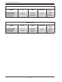
PWS-865-PQ
Model
SC732D4F-865B
SC732D4-865B
SC732D2-865B
SC732i-865B
CPU
HDD
I/O Slots
Power
Supply
DP/UP
4x 3.5"
2x 5.25"
(Optional)
7x FF
865W
highefficiency
PWS-502-PQ
Model
SC732D4F-500B
SC732D4-500B
SC732D2-500B
SC732i-500B
CPU
HDD
I/O Slots
Power
Supply
DP/UP
4x 3.5"
2x 5.25"
(Optional)
7x FF
500W
highefficiency
1-2
Chapter 1: Introduction
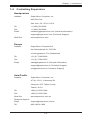
1-4 Contacting Supermicro
Headquarters
Address:
Super Micro Computer, Inc.
980 Rock Ave.
San Jose, CA 95131 U.S.A.
Tel:
+1 (408) 503-8000
Fax:
+1 (408) 503-8008
Email:
[email protected] (General Information)
[email protected] (Technical Support)
Web Site:
www.supermicro.com
Europe
Address:
Super Micro Computer B.V.
Het Sterrenbeeld 28, 5215 ML
's-Hertogenbosch, The Netherlands
Tel:
+31 (0) 73-6400390
Fax:
+31 (0) 73-6416525
Email:
[email protected] (General Information)
[email protected] (Technical Support)
[email protected] (Customer Support)
Asia-Pacific
Address:
Super Micro Computer, Inc.
4F, No. 232-1, Liancheng Rd.
Chung-Ho 235, Taipei County
Taiwan, R.O.C.
Tel:
+886-(2) 8226-3990
Fax:
+886-(2) 8226-3991
Web Site:
www.supermicro.com.tw
Technical Support:
Email:
[email protected]
Tel: 886-2-8226-1900
1-3
SC732 Chassis Manual
1-5 Returning Merchandise for Service
A receipt or copy of your invoice marked with the date of purchase is required before any warranty service will be rendered. You can obtain service by calling your
vendor for a Returned Merchandise Authorization (RMA) number. When returning
to the manufacturer, the RMA number should be prominently displayed on the
outside of the shipping carton, and mailed prepaid or hand-carried. Shipping and
handling charges will be applied for all orders that must be mailed when service
is complete.
For faster service, RMA authorizations may be requested online (http://www.supermicro.com/support/rma/).
Whenever possible, repack the chassis in the original Supermicro carton, using the
original packaging material. If these are no longer available, be sure to pack the
chassis securely, using packaging material to surround the chassis so that it does
not shift within the carton and become damaged during shipping.
This warranty only covers normal consumer use and does not cover damages incurred in shipping or from failure due to the alteration, misuse, abuse or improper
maintenance of products.
During the warranty period, contact your distributor first for any product problems.
1-4
Chapter 2: System Safety
Chapter 2
System Safety
2-1 Overview
This chapter provides a quick setup checklist to get your chassis up and running.
Following the steps in the order given should enable you to have your chassis set up
and operational within a minimal amount of time. This quick setup assumes that you
are an experienced technician, famailiar with common concepts and terminology.
2-2 Warnings and Precautions
You should inspect the box the chassis was shipped in and note if it was damaged
in any way. If the chassis itself shows damage, file a damage claim with carrier
who delivered your system.
Avoid areas where heat, electrical noise and electromagnetic fields are generated.
Position the chassis near at least one grounded power outlet.
2-3 Preparing for Setup
The SC732 chassis contains many features that are unique to the SC732 chassis
model. Read this manual in its entirety before beginning installation procedures.
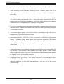
2-4 Electrical Safety Precautions
Basic electrical safety precautions should be followed to protect yourself from harm
and the SC732 from damage:
•Be aware of the locations of the power on/off switch on the chassis as well
as the room’s emergency power-off switch, disconnection switch or electrical
outlet. If an electrical accident occurs, you can then quickly remove power from
the system.
•Do not work alone when working with high-voltage components.
•Power should always be disconnected from the system when removing or in-
stalling main system components, such as the serverboard, memory modules
and optical device drives. When disconnecting the power, you should first power
2-1
SC732 Chassis Manual
down the server with the operating system and then unplug the power cords
from all the power supply modules in the system.
•When working around exposed electrical circuits, another person who is fa-
miliar with the power-off controls should be nearby to switch off the power, if
necessary.
•Use only one hand when working with powered-on electrical equipment. This
is to avoid making a complete circuit, which will cause electrical shock. Use
extreme caution when using metal tools, which can easily damage any electrical
components or circuit boards they come into contact with.
•Do not use mats designed to decrease electrostatic discharge as protection from
electrical shock. Instead, use rubber mats that have been specifically designed
as electrical insulators.
•The power supply power cord must include a grounding plug and must be
plugged into a grounded electrical outlet.
•Serverboard battery: CAUTION - There is a danger of explosion if the onboard
battery is installed upside down, which will reverse its polarities. This battery
must be replaced only with the same or an equivalent type recommended by
the manufacturer. Dispose of used batteries according to the manufacturer’s
instructions.
•Please handle used batteries carefully. Do not damage the battery in any way;
a damaged battery may release hazardous materials into the environment. Do
not discard a used battery in the garbage or a public landfill. Please comply
with the regulations set up by your local hazardous waste management agency
to dispose of your used battery properly.
•DVD-ROM laser: CAUTION - This server may have come equipped with a
DVD-ROM drive. To prevent direct exposure to the laser beam and hazardous
radiation exposure, do not open the enclosure or use the unit in any unconventional way.
2-2
Chapter 2: System Safety
2-5 General Safety Precautions
•Keep the area around the chassis clean and free of clutter.
•Place the chassis top cover and any system components that have been re-
moved away from the system or on a table so that they won’t accidentally be
stepped on.
•While working on the system, do not wear loose clothing such as neckties and
unbuttoned shirt sleeves, which can come into contact with electrical circuits or
be pulled into a cooling fan.
•Remove any jewelry or metal objects from your body, which are excellent metal
conductors that can create short circuits and harm you if they come into contact
with printed circuit boards or areas where power is present.
•After accessing the inside of the system, close the chassis back up and secure
it to the rack unit with the retention screws after ensuring that all connections
have been made.
2-6 System Safety
Electrostatic discharge (ESD) is generated by two objects with different electrical
charges coming into contact with each other. An electrical discharge is created to
neutralize this difference, which can damage electronic components and printed
circuit boards. The following measures are generally sufficient to neutralize this
difference before contact is made to protect your equipment from ESD:
•Do not use mats designed to decrease electrostatic discharge as protection from
electrical shock. Instead, use rubber mats that have been specifically designed
as electrical insulators.
•Use a grounded wrist strap designed to prevent static discharge.
•Keep all components and printed circuit boards (PCBs) in their antistatic bags
until ready for use.
•Touch a grounded metal object before removing any board from its antistatic
bag.
•Do not let components or PCBs come into contact with your clothing, which may
retain a charge even if you are wearing a wrist strap.
2-3
SC732 Chassis Manual
•Handle a board by its edges only; do not touch its components, peripheral chips,
memory modules or contacts.
•When handling chips or modules, avoid touching their pins.
•Put the serverboard and peripherals back into their antistatic bags when not
in use.
•For grounding purposes, make sure your computer chassis provides excellent
conductivity between the power supply, the case, the mounting fasteners and
the serverboard.
2-4
Chapter 3 System Interface
Chapter 3
System Interface
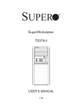
3-1 Overview
There are several LEDs on the control panel as well as others on the drive carriers
to keep you constantly informed of the overall status of the system as well as the
activity and health of specific components. This chapter explains the meanings of
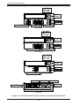
all LED indicators and the appropriate responses you may need to take. The following pages detail the features of the communication panel features of each of
the SC732 chassis models.
3-1
SC732 Chassis Manual
NIC LED
HDD LED
OH LED
Power
Button
Audio
Mic
2x IEEE 1394a
2x USB 2.0
2x USB 3.0
SC732D4F
NIC LED
HDD LED
OH LED
Power
Button
Audio
Mic
2x USB2.0
2x USB 3.0
SC732D4
NIC LED
HDD LED
OH LED
Power
Button
Audio
Mic
2x USB2.0
SC732D2
OH LED
HDD LED
NIC LED
Power
Button
2x USB2.0
SC732i
Figure 3-1: SC732 Communication Panels Listed by Chassis Model
3-2
Chapter 3 System Interface
3-2 Control Panel Buttons
Power: The main power button is used to apply or remove power from the power
supply to the system. When the power is on, the power button will be lighted by a
blue LED. Turning off the system power with this button will cause the blue LED
to turn off and will remove the main power, but will keep standby power supplied
to the system. Therefore, you must unplug system before servicing the system.
3-3 Communication Panel Components
The SC732 features a front communication panel allowing easy access to the chassis communication ports. The chassis models are equipped as follows:
SC732D4F model chassis:
•Two IEEE 1394a ports
•Two USB 2.0 ports
•Two USB 3.0 ports
•One audio port
•One microphone port
SC732D4 model chassis:
•Two USB 2.0 ports
•Two USB 3.0 ports
•One audio port
•One microphone port
3-3
SC732 Chassis Manual
SC732D2 model chassis:
•Two USB 2.0 ports
•One audio port
•One microphone port
SC732i model chassis:
•Two USB 2.0 ports
3-4
Chapter 3 System Interface
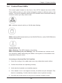
3-4 Control Panel LEDs
The control panel located on the front of the SC732 chassis has three LEDs.
These LEDs provide you with critical information related to different parts of the
system. This section explains what each LED indicates when illuminated and any
corrective action you may need to take.
NIC: Indicates network activity on GLAN when flashing.
HDD: Indicates IDE channel activity in the SAS/SATA drive, and/or DVD-ROM drive
activity when flashing.
Overheat/Fan Fail
When Flashing: This LED indicates a fan failure.
When Continuously On (not flashing): This LED indicates an overheat condition caused by cables obstructing the airflow in the system or the ambient room
temperature being too warm.
Correcting an Overheat/Fan Fail Condition
1. Check the routing of the cables and move any cables that restrict airflow.
2. Confirm that all fans are operating normally.
3. Verify that the heatsinks are installed properly.
4. If the chassis cover is not aligned correctly, the airflow may be disrupted. This
leads to overheating. Confirm that the chassis cover is placed correctly.
5. This LED will remain active as long as the overheat condition exists.
3-5
SC732 Chassis Manual
Notes
3-6
Chapter 4: Chassis Setup and Maintenance
Chapter 4
Chassis Setup and Maintenance
4-1 Overview
This chapter covers the steps required to install components and perform maintenance on the chassis. Most components of the SC732 do not require tools or
screws to set them up. Those components which must be secured with screws
require only a Phillips screwdriver. Print this chapter to use as a reference while
setting-up your chassis.
Note that due to the variety of features which are available on the front communication panels of the SC732 chassis models, the images shown of the front of the
chassis may differ from the actual chassis purchased.
!
Review the warnings and precautions listed in the manual before setting up or servicing this chassis. These include information in Chapter 2: System Safety and the warning/precautions listed in the setup instructions.
4-1
SC732 Chassis Manual
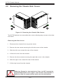
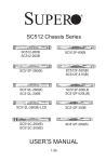
4-2 Removing the Chassis Side Covers
15
2
16
13
Figure 4-1: Removing the Chassis Side Covers
The SC732 features two removable side covers, allowing easy access to the chassis interior.
Removing the Side Covers
1. Disconnect the chassis from any power souce.
2. Remove the two screws securing the left side cover to the chassis.
3. Slide the left cover toward the rear of the chassis.
4. Lift the left cover from the chassis.
5. Remove the three screws securing the right side cover to the chassis.
6. Slide the right cover toward the rear of the chassis
7. Lift the right cover from the chassis.
!
Warning: Except for short periods of time, do NOT operate the
system without the cover in place. The chassis cover must be in
place to allow for proper airflow and to prevent overheating.
4-2
Chapter 4: Chassis Setup and Maintenance
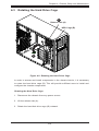
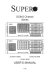
4-3 Rotating the Hard Drive Cage
2
Release Tab (A)
HDD Cage (B)
13
Figure 4-2: Rotating the Hard Drive Cage
In order to access and install components in the chassis interior, it is necessary
to rotate the hard drive cage (B). This will provide sufficient room to install and
configure the chassis components.
Rotating the Hard Drive Cage
1. Disconnect the chassis from any power source.
2. Lift the release tab (A).
3. Rotate the hard disk drive cage (B) outward.
4-3
SC732 Chassis Manual
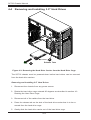
4-4 Removing and Installing 3.5" Hard Drives
4
5
Release Tabs
Figure 4-3: Removing the Hard Drive Carrier from the Hard Drive Cage
The SC732 chassis must be powered-down before hard drives can be removed
from the hard drive carriers.
Removing and Installing 3.5" Hard Drives
1. Disconnect the chassis from any power source.
2. Rotate the hard drive cage outward 90 degrees as described in section 4-3
Rotating the Hard Drive Cage.
3. Disconnect all of the cables from the hard drive.
4. Press the release tab on the side of the hard drive carrier that is to be removed from the hard drive cage.
5. Gently slide the hard drive carrier out of the hard drive cage.
4-4
Chapter 4: Chassis Setup and Maintenance
16
16
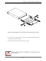
Figure 4-4: Removing the 3.5" Hard Drive from the Hard Drive Carrier
6. If a hard drive is already present, remove it by carefully pulling the sides of
the hard drive carrier outward.
7. Remove the hard drive from the hard drive carrier.
!
Warning: Only enterprise level HDDs are recommended for use
in this chassis.
4-5
SC732 Chassis Manual
11
1
19
Optional
Screw
Figure 4-5: Installing the Hard Drive Carrier into the Hard Drive Cage
8. Insert the new hard drive into the hard drive carrier.
9. Insert the hard drive carrier into the hard drive cage, sliding it towards the
back of the the hard drive cage until it clicks into a locked position.
10. If desired, each hard drive carrier may be secured to the exterior of the hard
drive cage using one optional screw.
11. Rotate the hard drive cage 90 degrees inward, returning it to the closed,
operational position in the chassis.
12. Connect the related cables to the hard drives.
4-6
Chapter 4: Chassis Setup and Maintenance
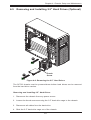
4-5 Removing and Installing 2.5" Hard Drives (Optional)
14
15
Thumb
Screw
Figure 4-6: Removing the 2.5" Hard Drives
The SC732 chassis must be powered-down before hard drives can be removed
from the hard drive carriers.
Removing and Installing 2.5" Hard Drives
1. Disconnect the chassis from any power source.
2. Loosen the thumb screw securing the 2.5" hard drive cage to the chassis.
3. Disconnect all cables from the hard drive.
4. Slide the 2.5" hard drive cage out of the chassis.
4-7
SC732 Chassis Manual
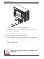
19
18
Figure 4-7: Installing 2.5" Hard Drives
5. If a hard drive is already present, remove it by carefully pulling the sides of
the hard drive carrier outward.
6. Remove the hard drive from the hard drive carrier.
7. Insert the new hard drive into the hard drive carrier.
8. Insert the hard drive carrier into the hard drive cage, sliding it towards the
back of the the hard drive cage until it clicks into a locked position.
9. Slide the 2.5" hard drive cage back into the chassis and tighten the thumb
screw to secure the cage.
10. Connect the related cables to the hard drive
!
Warning: Only enterprise level HDDs are recommended for use
in this chassis.
4-8
Chapter 4: Chassis Setup and Maintenance
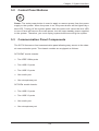
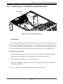
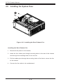
4-6 Installing the I/O Shield and Motherboard
I/O Shield
Figure 4-8: I/O Shield Placement
I/O Shield
An I/O shield holds the motherboard ports in place. Install the I/O shield before you
install the motherboard. The maximum size of motherboard supported by the SC732
is a 12" x 13" extended ATX motherboard. The motherboard is sold separately from
the SC732 chassis and comes with an I/O shield specific to the motherboard.
Installing the I/O Shield
1. Review the documentation that came with the motherboard. Become familiar
with component placement, requirements, and safety precautions.
2. Disconnect the chassis from any power source
3. With the illustrations facing the outside of the chassis, slide the I/O shield into
the space provided.
4. Once installed, the chassis will hold the I/O shield in place.
4-9
SC732 Chassis Manual
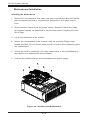
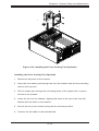
Motherboard Installation
Installing the Motherboard
1. Review the documentation that came with your motherboard. Become familiar
with component placement, requirements, precautions, and cable connections.
2. Disconnect the chassis from any power source. Rotate the hard drive cage
90 degrees outward, as described in the previous section, Rotating the Hard
Drive Cage.
3. Lay the motherboard in the chassis.
4. Secure the motherboard to the chassis using the rounded, Phillips head
screws provided. Do not exceed eight pounds of torque when tightening down
the motherboard.
5. Secure the CPU(s), heatsinks, and other components to the motherboard as
described in the motherboard documentation.
6. Connect the cables between the motherboard and power supply.
Figure 4-9: Installing the Motherboard
4-10
Chapter 4: Chassis Setup and Maintenance
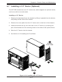
4-7 Installing a 3.5" Device (Optional)
The SC732D chassis has one 3.5" device slot, which supports an optional device,
such as an all-in-one card reader.
Installing a 3.5" Device
1. Remove the front bezel from the chassis by lifting it upwards from the bottom,
and pulling off the front of the chassis.
2. Remove the cover plate from the 3.5" device slot on the front of the chassis.
3. Install the bracket rail (A) onto one side of the 3.5" device, by inserting the
pins of the bracket into the mounting holes on the sides of the optical device.
4. Slide the 3.5" device into the chassis.
5. See Section 4-10 Installing the Front Bezel.
12
Remove
Cover Plate
1
4
Bracket
Rail (A)
13
Figure 4-10: Installing the 3.5" Device
4-11
SC732 Chassis Manual
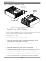
4-8 Installing Expansion Cards
Protective
Bracket (B)
Release
Latch (A)
13
12
PCI Card Slots
Figure 4-11: Locating Expansion Card Components
Expansion Card and PCI Slot Setup
The SC732 chassis includes seven PCI card slots for expansion cards. The number
of cards used varies, depending upon the motherboard models.
Installing Expansion Cards
1. Disconnect the chassis from any power source.
2. Depress the release latch (A) which holds the protective bracket (B) and
secures the add-on card brackets to the chassis.
3. Lower the protective bracket over the top of the expansion card dummy
brackets as shown in the lower illustration.
4. Remove the expansion card dummy brackets from their slots.
5. Simultaneously, slide the expansion card and its bracket into the slot on the
chassis, and insert the expansion card into its slot on the motherboard.
6. If desired, screws can be used to secure the expansion card into the chassis.
7. Close the protective bracket over the tops of the expansion card brackets.
4-12
Chapter 4: Chassis Setup and Maintenance
Full-Height, Full-Length
Card Holders (A)
12
Figure 4-12: Installing a Full-Height, Full-Length Expansion Card
Full-Height, Full-Length Expansion Card Setup
The SC732 chassis includes clips to accomodate the use of full-height, full-length
expansion cards. These clips support and stabilize the cards, preventing them from
contacting any undesired surfaces.
Installing Full-Height, Full-Length Expansion Cards
1. Locate the card holders (A), on the opposite side of the chassis from the addon card brackets.
2. Begin by installing the card as described in the previous section, Expansion
Card and PCI Slot Setup.
3. Push the card holder all the way down onto the end of the card to secure it in
the chassis.
4-13
SC732 Chassis Manual
4-9 Installing the System Fans
12
Figure 4-13: Installing the Rear Exhaust Fan
Installing the Rear Exhaust Fan
1. Disconnect all power to the chassis.
2. Insert the four rubber pins through mounting holes in the rear of the chassis
and through the mounting holes in the rear fan.
3. Pull the rubber pins through the mounting holes of the fan to secure the fan
to the chassis.
4. Connect the fan cable to the motherboard.
4-14
Chapter 4: Chassis Setup and Maintenance
4
Figure 4-14: Installing the Front Cooling Fan (Optional)
Installing the Front Cooling Fan (Optional)
1. Disconnect all power to the chassis.
2. Insert the four rubber pins through the front fan bracket and into the mounting
holes in the front fan.
3. Pull the rubber pins through the mounting holes of the system fan to secure
the fan to the chassis.
4. Lower the fan into the chassis, aligning the holes at the top of the front fan
bracket with the holes in the chassis.
5. Secure the fan to the chassis using the two screws provided.
6. Connect the fan cable to the motherboard.
4-15
SC732 Chassis Manual
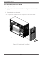
4-10 Installing the Front Bezel
Front Bezel Installation
1. Insert the tabs on the front bezel into the mounting holse on the front of the
chassis.
2. Ensure that the cover fits snugly.
This completes the installation of basic components in the SC732 chassis
1
Figure 4-15: Installing the Front Bezel
4-16
Chapter 4: Chassis Setup and Maintenance
4-11 Power Supply
The SC732 chassis includes either a 500 Watt or a 865 Watt power supply. In the
unlikely event that it becomes necessary to replace the power supply, follow the
instructions below.
Power Supply
Figure 4-16: Removing the Power Supply
Changing the Power Supply
1. Disconnect the chassis from any power source.
2. Disconnect the motherboard cables.
3. Remove the screws securing the power supply to the chassis, which are
located on the rear of the chassis. Set these screws aside for later use.
4. Gently lift the power supply out of the chassis.
5. Replace the failed power supply with an identical power supply model.
6. Secure the new power supply using the screws previously set aside.
7. Plug the AC power cord back into the module and power-up the system.
4-17
SC732 Chassis Manual
Notes
4-18
Appendix A: Chassis Cables
Appendix A
Cables, Screws,
and other Accessories
A-1 Overview
This appendix lists the supported cables for the SC732 chassis. It only includes
the most commonly used components and configurations. For more compatible
cables, refer to the manufacturer of the motherboard and our Web site at: www.
supermicro.com.
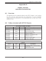
A-2 Cables Included with SC732 Chassis
SC732D4F, SC732D4, SC732D2
Part #
Type
Quantity
Description
CBL-0071L
Cable
1
Front panel cable, 16-pin to 16-pin,
30" (76 cm)
CBL-0084L
Cable
1
Split converter cable
CBL-0453L
Cable
2
USB 3.0 internal cable
(19-pin to 19-pin)
CBL-0454L
(Optional)
Cable
2
USB 3.0 to 2.0 adapter cable
(19-pin to 19-pin)
CBL-0455L
Cable
1
HD/AC 97 audio cable
CBL-0263L
Cable
2
FireWire 1394 cable
SC732i
Part #
Type
Quantity
Description
CBL-0071L
Cable
1
Front panel cable, 16-pin to 16-pin,
30" (76 cm)
CBL-0084L
Cable
1
Split converter cable
A-1
SC732 Chassis Manual
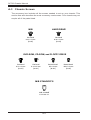
A-3 Chassis Screws
The accessory box includes all the screws needed to set up your chassis. This
section lists and describes the most commonly used screws. Your chassis may not
require all of the parts listed.
M/B
HARD DRIVE
Pan head
6-32 x 5 mm
[0.197]
Flat head
6-32 x 5 mm
[0.197]
DVD-ROM, CD-ROM, and FLOPPY DRIVE
Pan head
6-32 x 5 mm
[0.197]
Flat head
6-32 x 5 mm
[0.197]
Round head
M3 x 5 mm
[0.197]
M/B STANDOFFS
M/B standoff
6-32 to 6-32
A-2
Round head
M2.6 x 5 mm
[0.197]
Appendix B: Power Supply Specifications
Appendix B
SC732 Power Supply Specifications
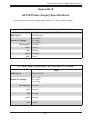
This appendix lists power supply specifications for your chassis system.
SC732D4F-500B, SC732D4-500B, SC732D2-500B, SC732i-500B
500W
MFR Part #
PWS-502-PQ
Rated AC Voltage
100 - 240V
50 - 60Hz
12 - 6 Amp
+5V standby 6.5 Amp
+12V
69 Amp
+5V
30 Amp
+3.3V
-12V
305 Amp
1 Amp
SC732D4F-865B, SC732D4-865B, SC732D2-865B, SC732i-865B
865W
MFR Part #
PWS-865-PQ
Rated AC Voltage
100 - 240V
50 - 60Hz
12 - 6 Amp
+5V standby 6.5 Amp
+12V
70 Amp
+5V
30 Amp
+3.3V
30 Amp
-12V
1 Amp
B-1
SC732 Chassis Manual
Disclaimer (cont.)
The products sold by Supermicro are not intended for and will not be used in life support systems, medical equipment, nuclear facilities or systems, aircraft, aircraft devices,
aircraft/emergency communication devices or other critical systems whose failure to perform be reasonably expected to result in significant injury or loss of life or catastrophic
property damage. Accordingly, Supermicro disclaims any and all liability, and should
buyer use or sell such products for use in such ultra-hazardous applications, it does so
entirely at its own risk. Furthermore, buyer agrees to fully indemnify, defend and hold
Supermicro harmless for and against any and all claims, demands, actions, litigation,
and proceedings of any kind arising out of or related to such ultra-hazardous use or
sale.
B-2