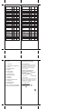
1
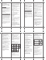
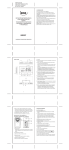
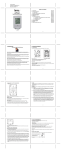
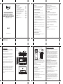
Table of contents
MULTI-FUNCTIONAL WEATHER
STATION WEATHER FORECAST,
BAROMETER, IN-OUT THERMOHYGRO METER, MOON PHASE, HEAT
INDEX, SUNRISE SUNSET AND RADIO
CONTROLLED CLOCK
1. Introduction ............................................ Page 3
2. Starting up your HBR657 ....................... Page 8
3. Using your HBR657 ............................... Page 9
(navigating between different modes)
4. Pressure and weather forecast mode....... Page 9
5. Temperature and humidity mode ............ Page 13
6. Sunrise and sunset mode......................... Page 18
7. Clock and alarm mode............................ Page 20
8. Care Instructions..................................... Page 26
9. Support ................................................... Page 26
10. Technical Specifications ......................... Page 27
11. Appendix ................................................ Page 29
A DISPLAY
All functions are to be seen on the LCD. The
functions are described in this manual.
G CHANNEL BUTTON
Changes temperature and humidity display to
selected channel
Press and hold to enable cycling display of channel
temperature and humidity.
B SNOOZE/LIGHT BUTTON
Activates the backlight and snooze function
C ALARM/CHART BUTTON
Depending on the selected mode, this key has
different functions:
- Select and display the alarm time (Time Mode). For
setting, press and hold the key
- HI/LO temperature alarm (Thermo/Hygro Mode).
For setting, press and hold the key
- Storm alert ON/OFF or hold to display temperature
and humidity bar-charts (Weather Mode)
D SET BUTTON
Short press in each mode: scans through the various
options.
Press and hold in the displayed mode: Enter Set-Up
or change the unit. Then a short press confirms the
setting.
HBR657
E MEM BUTTON
Shows records for moon phase,
temperature/humidity, sunrise/sunset
H (-) BUTTON
- Switches to next mode in clockwise direction
- Decreases the value in any setting mode
- Activates sensor search (hold key in Thermo mode)
- Thermo Alarm ON/OFF (Thermo Mode; Alarm
setting)
I (+) BUTTON
- Switches to next mode in anti-clockwise direction
- Advances the value in any setting mode
- Starts RC reception (hold key in Time Mode)
- Thermo Alarm ON/OFF (Thermo Mode; Alarm
setting)
J BATTERY COMPARTMENTS
Accommodates 4 UM-3 or “AA” size 1.5V batteries
K DC JACK
Plug-in for the 7.5V 200mA transformer
F HISTORY BUTTON
Enters weather mode and then shows history for the
sea-level pressure (past 24h)
Operating Instructions
2
5
6
IROX TE657 & TS33C MANUAL (ENG)
SIZE: W65 X H105 (mm)
BY WING TSUI 13/06/08
1. INTRODUCTION
Congratulations on your purchase of the HBR657.
Soft-touch button design provides you a novel key
interface and outlook design.
REMOTE THERMO-HYGRO SENSOR
Features
MAIN UNIT
E
B
B
RESET
1 2 3
CHANNEL
The basic package comes with 1 weather forecast
station and 1 remote thermo-hygrometer sensor.
A
A
The main unit is equipped with the built-in barometer
which enables to display the weather forecast,
barometer and altimeter.
NOTE: LED INDICATOR ON FRONT SIDE
Flashes once when the remote unit transmits a reading
Flashes twice when low battery is detected on sensor unit
(compatible Irox Models HTS33, HTS55, HTS12C,
HTC13, HTS13)
The main unit is capable of keeping track of the
temperature and humidity of different sites. A HI/LO
alarm can be set for the remote sensors. No wire
installation is required as the sensors operate at
433MHz.
Apart from the temperature, it shows the indoor and
outdoor relative humidity and rates the comfort level. It
also retains the maximum and minimum relative
humidity readings. The unit is able to receive and
display readings from up to 3 remote sensors.
C
D
E
F
G
H
I
A BATTERY COMPARTMENT
Accommodates 2 UM-3 or “AA” size 1.5V batteries
B RESET BUTTON
Restart all functions after setting a new channels adn
after changing the batteries
C UNIT BUTTON
Toggles the unit of temperature (if applicable)
If the weather forecast detects "storm", an alarm will be
activated.
J
K
D CHANNEL SELECTOR
Channel is to be selected before batteries are installed
E WALL MOUNT HOLE
For mounting the sensor on the wall
3
C
D
4
7
2. STARTING UP YOUR HBR657
For best operation,
1. Insert batteries for remote units before doing so for the
main unit.
2. Position the remote unit and main unit within effective
transmission range, which, in an open and noise free
field, can be up to 30 meters. Note that the effective
range is vastly affected by the building materials and
where the main and remote units are positioned.
Try various set-ups for best result. Though the remote
units are weather proof, they should be placed away
from direct sunlight, rain or snow.
Note: See also chapter "4.b Setting Pressure Parameters
during Initial Start-Up"
BATTERY INSTALLATION: REMOTE UNIT
1. Remove the screws on the battery compartment.
2. Select the channel
3. Install 2 batteries (UM-3 or “AA” size 1.5V) strictly
according to the polarities shown and press RESET.
4. Replace the battery compartment door and secure its screws.
POWER INSTALLATION: MAIN UNIT
1. Plug in the provided 7.5V 200mA transformer to the
DC jack of bottom side.
Or
2. Open the battery compartment door.
3. Install 4 batteries (UM-3 or “AA” size 1.5V) strictly
according to the polarities shown.
4. Replace the battery compartment door.
Note:
1. To provide reliable key operation under almost any
condition, the soft-touch buttons will self-calibrated in
1 second on power-up. Please leave your hands or
anything away from the soft-touch key when power-up.
2. The main unit is designed for use with batteries or power
adapter. For back-up purpose, always keep good
batteries in the unit!
8
LOW BATTERY WARNING
When it is time to replace batteries for the remote
sensor, the respective low-battery indicator [
]
will show up on the indoor or outdoor temperature &
hygrometer display.
3. USING YOUR HBR657
(NAVIGATING BETWEEN DIFFERENT MODES)
There are 6 sections available on the main console unit,
and each one displays a different information.
When the display is in one of the 4 modes which can be
operated, its corresponding icon will start flashing. To
navigate between these 4 modes, press “+” or “-” to
cycle through them.
The Heat index section is a fixed mode. It cannot be
navigated into this section.
4. PRESSURE AND WEATHER FORECAST MODE
Important: All operations described in here are to be
made in the Weather mode
This part of the display indicates the current pressure,
sea level pressure, weather forecast and pressure trend.
A number of historical statistics can also be viewed,
such as the sea-level pressure values for the last 24
hours, as well as a pressure/ temperature/ humidity
history bar-chart.
Pressure values may be displayed inHg, hPa/mBar or
mmHg, and altitude values may be displayed in meters
or feet.
a) Accessing Pressure and Weather Forecast Mode
From the main console unit: Press “+” or “-” until the
weather forecast icon
on the upper left of the
display starts flashing.
9
e) Setting the Pressure and Altitude Units
1. In Pressure and Weather Forecast Mode, press SET
until local pressure is displayed.
2. Press and hold MEM. The pressure unit starts
flashing.
3. Set Local Pressure Units: Press “+” or “-” to adjust.
Press MEM to confirm your selection.
4. In Pressure and Weather Forecast Mode, press SET
until Sea-Level Pressure is displayed.
5. Press and hold MEM. The pressure unit starts
flashing.
6. Set Sea-Level Pressure Units: Press “+” or “-” to
adjust. Press MEM to confirm your selection.
7. In Pressure and Weather Forecast Mode, press SET
until the set altitude is displayed.
8. Press and hold MEM. The altitude unit starts
flashing.
9. Set Altitude Units: Press “+” or “-” to adjust (feet
or meter). Press MEM to confirm your selection.
f) Viewing the Sea Level Pressure History
1. Pressing HISTORY will activate the sea level
pressure display.
2. When sea level pressure is displayed, press
HISTORY repeatedly to view sea level pressure
data for each of the last 24 hours.
3. If no buttons are pressed for 5s, the display
automatically returns to Pressure and Weather
Forecast Mode.
b) Setting Pressure Parameters during Initial Start-Up
During the initial start-up of the main console unit, all
functions in Pressure and Weather Forecast mode will
be locked until the pressure settings are configured.
1. Choose Pressure Units:
The icon “hPa/mBar” starts flashing. Press “+” or “-”
to select pressure unit as inHg, hPa/mBar or mmHg
Press SET to confirm your selection.
2. Choose Altitude Units:
Press “+” or “-” to select altitude unit as feet or meters.
Press SET to confirm your selection.
3. Set Altitude:
Press “+” or “-” to adjust value. Press and hold
either button for fast advance. Press SET to confirm
your selection.
4. Upon completion the display will be returned to
Pressure and Weather Forecast Mode.
c) Viewing Pressure and Altitude Data
In Pressure and Weather Forecast Mode, each press of
SET rotates display between:
- Sea level pressure
- Local pressure
- Local altitude
d) Setting the Sea Level Pressure or the local altitude
1. In Pressure and Weather Forecast Mode, press SET
until the sea level pressure is displayed.
2. Press and hold SET. The Sea Level Pressure display
starts flashing.
3. Set Sea Level Pressure:
Press “+” or “-” to adjust. Press and hold either
button for fast advance.
Press SET to confirm your selection.
4. Upon completion the display will be returned to
Pressure and Weather Forecast Mode.
The same procedure can be done to set the altitude.
Instead of selecting the sea level, select the altitude display.
Please note: Any setting made in either mode will adjust
automatically the other one!
10
g) Viewing the Pressure/ Temperature/ Humidity
Bar-Charts
The bar-chart on the display can be configured to
display the history data for sea-level pressure,
temperature or humidity for channel 1.
In Pressure and Weather Forecast Mode, press and hold
ALARM/CHART, to toggle the bar-chart between:
- Sea-level pressure (“PRESSURE” will be displayed)
- Temperature (Thermometer icon and “CH1” will
be displayed)
- Humidity (RH icon and “CH1” will be displayed)
h) Weather forecast
The unit is capable of detecting atmospheric pressure
changes. Based on collected data, it can predict the
weather for the forthcoming 12 to 24 hours.
Symbol
of Display
Forecast
Sunny
Slightly
Cloudy
Cloudy
Little
Rainy
Symbol
of Display
Forecast
Heavy
Rainy
Heavy
Snowy
Storm
NOTE:
1. The accuracy of a general pressure-based weather
forecast is about 70%.
2. The weather forecast may not reflect the current
situation necessarily.
3. The “Sunny” icon implies clear weather at night.
11
12
"Storm" is meaning a dramatic pressure drop with the
potential of a storm. An acoustic warning for this
situation can be activated or deactivated in the
following way:
Press ALARM/CHART in Pressure and Weather
Forecast Mode. Then press ALARM/CHART to turn
ON or OFF the storm alert function. It will return to
pressure display automatically after 5s.
• Weather Alarm
The weather alarm sound will be activated when it is
change to heavy rainy, heavy snow and storm.
5. TEMPERATURE AND HUMIDITY MODE
Important: All operations described in here are to be
made in the Temperature/Humidity mode.
The weather station supports up to 3 remote
thermo-hygro sensors, each sensor corresponding to a
separate channel for the temperature and relative
humidity display. The temperature may be shown in
degrees Celsius ºC or degrees Fahrenheit ºF. The trend
(rising, steady or falling) of the values is also indicated
on the display.
The main console unit uses the indoor temperature and
humidity data to compute a comfort level rating of Wet,
Comfort or Dry.
A temperature alert function is available for each
channel. It can be programmed to sound if the channel
temperature exceeds or falls below the pre-configured
upper and lower limits.
Note: The temperature alerts have a 0.5 ºC hysteresis to
prevent the alerts from sounding constantly due to small
fluctuations near the alert value. This means that after
the temperature reaches the alert value, it will have to
fall below the alert value plus the hysteresis to
deactivate the active alert.
a) Accessing Temperature and Humidity Mode
From the main console unit: Press “+” or “-” until the
IN icon
starts flashing.
b) Viewing Temperature and Humidity Display for
each Channel
For Static Display:
In Temperature and Humidity Mode, each press of
CHANNEL rotates display between different channels.
For Cycling Display:
To enable automatic rotating between different channel
displays, press and hold CHANNEL, until the
icon
is displayed. Each valid channel will now be displayed
for 5s.
c) Setting Units for Temperature Display (ºC or ºF)
In Temperature and Humidity Mode, press and hold
SET to convert units between degrees Celsius ºC and
degrees Fahrenheit ºF.
d) Activating/Deactivating the Temperature Alertsl
1. In Temperature and Humidity Mode, each press of
ALARM/CHART rotates channel temperature
display between:
- Current Temperature for corresponding channel
- Upper Temperature Alert (displays OFF if
deactivated):
icon displayed
13
- Lower Temperature Alert (displays OFF if
deactivated):
icon displayed
When the above alerts are displayed, pressing “+” or
“-” will activate/deactivate the corresponding alert.
• Temperature Alarm
The temperature alarm will sound when the temperature
is out of the pre-set range.
e) Setting up the Temperature Alerts
1. In Temperature and Humidity Mode, press
ALARM/CHART to select the alarm which you
wish to configure.
2. Press and hold ALARM/CHART until channel
temperature and
or icon starts flashing in
the display.
3. Set Value for Temperature Alert:
Press “+”or “-” to adjust value. Press and hold either
button for fast advance.
Press ALARM/CHART to confirm your selection.
4. Upon completion the display will be returned to
the temperature alert selection screen.
f) Interrupt a triggered alarm
To Disable Temperature Alarm(s):
Press ALARM/CHART to disable the alarm (s).
g) Viewing the Max/Min Channel Temperature and
Humidity
In Temperature and Humidity Mode, each press of
MEM rotates the selected temperature and humidity
(IN, CH1-5) between:
- Current temperature and humidity
- Minimum temperature and humidity
- Maximum temperature and humidity
15
14
h) Resetting the Max/Min Channel Temperature
and Humidity Memory
In Temperature and Humidity Mode, press and hold
MEM 3-4 seconds to clear memory for all channels
(there will be no key sound to confirm)
i) Main Unit and Remote Sensor Status
The kinetic wave display shows the signal receiving
status of the main unit. There are three possible forms:
The unit is in searching mode.
Temperature readings are
securely registered.
˚C
No signals.
j) Activating Main Console Unit to Search for
All Remote Sensor Signals
The main console unit may be manually activated to
search for signals from all remote sensors.
Press and hold “-” to start a search.
k) Disconnected Signals
If without obvious reasons the display of the outdoor
temperature goes blank. Hold “-” for 2 seconds to start
an immediate search. If that fails, check:
1. The remote unit is still in place.
2. The batteries of both the remote unit and main unit.
Replace as necessary.
Note: When the temperature falls below freezing point,
the batteries of outdoor units will get cold too and
subsequently lowering their voltage supply and the
effective transmission range.
16
3. The transmission is within range and path is clear of
obstacles and interference. Shorten the distance when
necessary.
l) Transmission Collision
Signals from other household devices, such as door
bells, home security systems and entry controls, may
interfere with those of this product and cause
temporarily reception failure. This is normal and does
not affect the general performance of the product.
The transmission and reception of temperature readings
will resume once the interference recedes.
Category
Heat Index (°C)
normal
< 27°C
caution
27 – 32°C
Level
extreme caution 32 – 41°C
danger
41 – 54°C
extreme danger
> 54°C
m) Heat Index
The heat index is based on the temperature and
humidity measurements of the channel 1 sensor.
The heat index is an index that combines air
temperature and dew point in an attempt to determine
the human-perceived equivalent temperature — how hot
it feels, termed the "felt air temperature". The human
body normally cools itself by perspiration, or sweating,
which evaporates and carries heat away from the body.
However, when the relative humidity is high the
evaporation rate is reduced, so heat is removed from the
body at a lower rate causing it to retain more heat than
it would in dry air. Measurements have been taken
based on subjective descriptions of how hot subjects
feel for a given temperature and humidity, allowing an
index to be made which corresponds a temperature and
humidity combination to a higher temperature in dry air.
The heat index contains average assumptions about the
human body mass and height, clothing, and the wind
speed.
6. SUNRISE AND SUNSET MODE
Important: All operations described in here are to be
made in the Sunrise/Sunse mode
The main console unit computes the sunrise and sunset
times from the user-configured location data. This
includes the longitudes, latitude, time zone and DST
(Daylight Saving Time). Choosing a suitable city code
for your location will automatically generate the correct
values for the location data.
Should you wish to input your own location data or if a
suitable city code could not be found, choose “USR” as
the city code during setup. A searching function is also
available, which allows the sunrise/sunset times for
different dates to be viewed.
17
18
b) Setting up the Location Data
i) In Sunrise/Sunset Mode, press and hold SET to
enter location data setup.
ii) The city code in the Time and Alarm display should
start flashing. Set City Info: Press “+” or “-” to
select a city for your local area. Refer to the
Appendix section for a list of available codes. The
corresponding longitude and latitude will be shown
along with the city. Should you wish to input your
own geographical coordinates, choose “USR”
as the city code. Press SET to confirm your
selection.
iii) If “USR” was chosen, you will be asked to input
your geographical coordinates. Set Degree of
Latitudes: Press “+” or “-” to adjust value. Press
and hold either button for fast advance. Press SET
to confirm your selection. Repeat above procedure
to set minute of latitude, degree of longitude, minute
of longitude, time zone and DST selection.
iv) Upon completion the display will be returned to
Sunrise/Sunset Mode.
Note: Press and hold SET anytime during the setup to
return to normal Clock and Alarm mode. All setting will
be discarded.
a) Accessing Sunrise/Sunset Mode
From the main console unit: Press “+” or “-” until the
sunrise and sunset icons
on the lower left of the
display start flashing.
3. Press MEM or SET to return display to
Sunrise/Sunset Mode.
e) Understanding the Sunrise/Sunset Display
The sunrise time being displayed differs during the
morning and the afternoon/night.
From 12 am to 12 pm:
The sunrise time for the current day will be displayed.
From 12 pm to pm:
The sunrise time for the next day will be displayed.
“NEXT DAY” icon will be displayed above the sunrise
time.
At certain locations (especially those at high latitudes),
sunrise and sunset events may not occur within a 24
hours time frame.
19
Accessing Clock and Alarm Mode
From the main console unit: Press + or - until the clock
icon
beside the time/date display starts flashing.
7.1 Time Function
HOW TO SET THE RADIO CONTROLLED
CLOCK
1. After the batteries are installed. The clock will
search the radio signal automatically (DCF77 from
Germany). It takes about 3-10 minutes to finish this
process.
2. If you wish to disable the auto-reception feature,
hold “+” for 2 seconds to disable it.
3. To enable the auto-reception feature again, hold “+”
for 2 seconds again to start the reception and the
regular synchronisations.
4. If the radio signal is received, the date & time will
be set automatically and the radio control signal
icon [
] turns on.
5. If the clock fails to receive the time signal, it will
show the [ ] icon. If the time is not correct, you
may set the time manually.
HOW TO SET THE CLOCK MANUALLY
To set the clock manually, hold “SET” for 2 seconds.
Now it will show the language. You may choose among
English (ENG), German (GER), French (FRE), Italian
(ITA), Spanish (SPA) and Dutch (DUT). Press “+” or
“-” to change it.
Press “SET” to confirm. Repeat the same procedure to
set your nearest city (default is "Frankfurt", see belwo
for more details), year, month, date, date-month
format,12/24 hour format, hour and minute. During the
setting, press and hold “+” or “-” will increase or
decrease the value rapidly.
21
Rotating between Different Clock/Calendar Displays
Pressing SET rotates the clock display between:
- Hour: Minute: Weekday
- Hour: Minute: City
- Hour: Minute: Second
- Month: Day: Year (or Day: Month Year depending
on settings)
- Hour: Minute for UTC (Coordinated Universal Time)
7.2 Wake-Up Alarm Function
There are three time alarms available on the console
unit:
Weekday alarm: activated everyday from Monday to
Friday at specified time
Single alarm: activated once at specified time
Pre-alarm: activated at specified time interval
(15- 90 min) ahead of weekday alarm, if channel 1
temperature falling to +2 ºC or below.
The snooze duration for the above alarms can also be
programmed (1-15 min).
Activating/Deactivating the Time Alarms
1. Press ALARM/CHART to rotate between:
- Weekday Alarm Time (displays OFF if weekday
alarm deactivated)
- Single Alarm Time (displays OFF if single alarm
deactivated)
- Pre-Alarm Time (displays OFF if pre-alarm
deactivated)
2. When the above alarms are displayed, pressing “+”
or “-” will activate/deactivate the corresponding
alarm.
c) Viewing the Location
In Sunrise/Sunset Mode, each press of SET rotates
display between:
1. Time and sunrise/sunset times
2. Calendar and sunrise/sunset times
3. Calendar and longitude/latitude
d) Viewing Sunrise/Sunset Times for Different Dates
1. In Sunrise/Sunset Mode, press MEM.
2. The date should be flashing.
Press “+” or “-“ to adjust date. Press and hold either
button for fast advance. The corresponding sunrise
and sunset times will be displayed for the selected
date.
7. CLOCK AND ALARM MODE
Important: All operations described in here are to be
made in the clock mode
Note: Press SET anytime during alarm selection mode
to return to normal clock display.
20
23
If there is an item you do not wish to change, simply
press “SET” to bypass the item. When you finished the
change, press “SET” to exit. The display will return to
the clock mode.
Details about the time setting mode (in "city code"
section)
1. In the city setting, you may chose any of the preset
locations (see the list in the Appendix).
2. If USR (=USER location) is selected, you may set
your own latitude and longitude and timezone
Set Latitude / Longitude:
You will be asked to enter your latitude in degrees (º).
Press “+” or “-” to adjust value. Press and hold either
button for fast advance.
Press SET to confirm your selection.
Repeat above procedure to set the minutes for the
latitude (‘), the northern or southern hemisphere and
then the degrees for the longitude and the minutes for
longitude and again the eastern or western hemisphere
Set Time Zone (TZ):
Press “+” or “-” to adjust value in steps of 30 min.
Press and hold either button for fast advance.
Press SET to confirm your selection.
Set Daylight Saving Time Option:
Press “+” or “-” to turn DST option on or off. Press and
hold either button for fast advance. The various options
you may find in the Appendix in the "DST definition".
Press SET to confirm your selection.
Note: You may press and hold SET anytime during the
setup to return to the normal Clock and Alarm Mode.
All settings made will then be discarded. The same will
happen, if you do not press any key in the setting mode
for more than 2 minutes,
22
Setting up the Time Alarms
1. Press ALARM/CHART to select the alarm which
you wish to configure.
2. Press and hold ALARM/CHART until hour starts
flashing in the display
3. Set Alarm Hour:
Press “+” or “-” to adjust value. Press and hold
either button for fast advance.
Press ALARM/CHART to confirm your selection.
4. Set Alarm Minutes:
Press “+” or “-” to adjust value. Press and hold
either button for fast advance.
Press ALARM/CHART to confirm your selection.
5. Set Duration of Snooze Function (all three alarms
share same snooze time duration, default 8 minutes,
1 to 15 minutes can be set):
Press “+” or “-” to adjust value. Press and hold
either button for fast advance.
Press ALARM/CHART to confirm your selection.
6. Upon completion the display will be returned to
the alarm selection screen.
Note: Pre-alarm cannot be activated if weekday alarm
or single alarm is not enabled.
ALARM FEATURE
• Weekday Alarm “
”
The alarm sound will be activated and the icon will be
flashed on weekday when it is armed and the alarm
time is reached.
• Single Alarm “
”
The alarm sound will be activated and the icon will be
flashed when it is armed and the alarm time is reached.
Once it finished, it will be disabled automatically
• Pre-Alarm “Pre-AL”
The pre-alarm sound will be activated and the icon will
be flashed if the temperature of channel 1 is under or
equal two degree C.
It is programmable 15, 30, 45, 60 or 90 minutes earlier
than the weekday alarm or single alarm time.
24
Disabling/Entering Snooze when Time Alarms are
activated
To Enter Snooze: Press SNOOZE to enable snooze
function.
Note: Alarm will automatically enter snooze mode if no
key is pressed after the alarm sounds for 2 minutes.
This will occur for a maximum of three times.
To Disable Alarm(s):
Press ALARM/CHART to disable the alarm (s).
Note: For weekday alarm, pressing ALARM/CHART
will only disable the alarm for the current day. The
alarm will be activated again the next day (if it falls
within Monday to Friday).
7.3 Understanding the Moon Phase Diagram
New Moon Waxing
Crescent
Full Moon
Waning
Gibbous
First
Quarter
Last
Quarter
Waxing
Gibbous
Waning
Crescent
8. CARE INSTRUCTIONS
- Do not expose the device to extreme temperatures
or direct sunlight over longer periods.
- Avoid blows and shocks of any kind to the device.
- For cleaning use a dry soft cloth that you have
moistened with water and a mild cleaning agent.
Never use volatile substances such as benzene,
thinner, cleansing agents in spray cans etc..
- When the device is not being used store it in a dry
area and out of the reach of small children.
- If the device is activated under extreme coldness
it may occur that the display becomes illegible. As
soon as it is returned to a warm environment the
device will function normally.
- Please keep the user’s manual and other documents
delivered with the device stored carefully so that
you can reference them at a later point if necessary.
- Please use only new batteries and never mix old
and new batteries.
- Please also remember that old batteries should not
be disposed of with household waste but should
be handed in at the designated collection centres.
- Important: With all Irox appliances, all disposal fees
in Switzerland (vRG; advance recycling fee) and
in the EU (WEEE) have been paid.
9. SUPPORT
This device is a new development of Irox Development
Technology. All information was made and checked by
means of a functioning instrument. It may occur that
adjustments and improvements of the device will take
place that due to typographical procedures were not
able to be listed in this manual. Should you notice
deviations which make it difficult for you to operate
and use the instrument you may at any time download
the latest manual onto your PC free of charge at
www.irox.com.
© Irox Development Technology
25
10. SPECIFICATIONS
Temperature Measurement
Main unit
Proposed operating range :
Remote thermo-hygro unit
Proposed operating range :
-20.0°C to +50.0°C
-4.0°F to 122.0°F
0.1°C
0.2°F
Resolution :
Relative Humidity Measurement
Main unit
Measuring range :
25% to 95%
Resolution :
1%
Remote thermo-hygro unit
Measuring range :
25% to 95%
Resolution :
1%
RF Transmission
Remote thermo-hygro unit
Frequency :
433MHz
Maximum number of remote unit : 3
Range :
Maximum 60 meters
(open area)
Cycle :
43 ~ 47 seconds
Calendar Clock
12/24 h display with hh : mm
Date Format : Day - Month or Month-Day.
Day of week selectable in 6 languages
(ENG, GER, FRE, ITA, SPA and DUT)
Dual 2-minute crescendo alarm with snooze
Pre-alarm for ice alert
Temperature alarm
Weather alarm for storm
Power
Main unit :
Remote thermohygro unit :
7.5V 200mA DC transformer
4 pcs UM-3
or “AA” size 1.5V battery
2 pcs UM-3
or “AA” size 1.5V battery
Weight
Main unit :
459g (Without battery)
Remote thermohygro unit :
62g (Without battery)
Dimension
Main unit :
218 (L) x 122(H) x 30(D) mm
Remote thermohygro unit :
55.5(L) x 101(H) x 24(D) mm
Barometric Pressure Measurement
Measuring range :
750 to 1100 hPa/mBar
at 25°C
(22.15 to 32.49 inHg)
Sampling cycle :
20 minutes
27
City
Code
Atlanta, Ga.
Austin, Tex.
Baltimore, Md.
Birmingham, Ala.
Boston, Mass.
Calgary, Alba., Can.
Chicago, IL
Cincinnati, Ohio
Cleveland, Ohio
Columbus, Ohio
Dallas, Tex.
Denver, Colo.
Detroit, Mich.
El Paso, Tex.
Houston, Tex.
Indianapolis, Ind.
Jacksonville, Fla.
Las Vegas, Nev.
Los Angeles, Calif.
Seattle, Wash.
St. Louis, Mo.
Tampa, Fla.
Toronto, Ont., Can.
ATL
AUS
BWI
BHM
BOS
YYC
CGX
CVG
CLE
CMH
DAL
DEN
DTW
ELP
HOU
IND
JAX
LAS
LAX
SEA
STL
TPA
YTZ
26
-5.0°C to +50.0°C
23.0°F to 122.0°F
0.1°C
0.2°F
Resolution :
11. APPENDIX
US and Canadian Cities
28
Zone
Offset
-5
-6
-5
-6
-5
-7
-6
-5
-5
-5
-6
-7
-5
-7
-6
-5
-5
-8
-8
-8
-6
-5
-5
DST
City
Code
SU
SU
SU
SU
SU
SU
SU
SU
SU
SU
SU
SU
SU
SU
SU
NO
SU
SU
SU
SU
SU
SU
SU
Memphis, Tenn.
Miami, Fla.
Milwaukee, Wis.
Minneapolis, Minn.
Montreal, Que., Can.
Nashville, Tenn.
New Orleans, La.
New York, N.Y.
Oklahoma City, Okla.
Omaha, Neb.
Ottawa, Ont., Can.
Philadelphia, Pa.
Phoenix, Ariz.
Pittsburgh, Pa.
Portland, Ore.
San Antonio, Tex.
San Diego, Calif.
San Francisco, Calif.
San Jose, Calif.
Vancouver, B.C., Can.
Washington, D.C.
Vancouver, Canada
MEM
MIA
MKE
MSP
YMX
BNA
MSY
NYC
OKC
OMA
YOW
PHL
PHX
PIT
PDX
SAT
SAN
SFO
SJC
YVR
DCA
VAC
29
Zone
Offset
-6
-5
-6
-6
-5
-6
-6
-5
-6
-6
-5
-5
-7
-5
-8
-6
-8
-8
-8
-8
-5
-8
DST
SU
SU
SU
SU
SU
SU
SU
SU
SU
SU
SU
SU
NO
SU
SU
SU
SU
SU
SU
SU
SU
SU
30
World Cities
City
Code
Addis Ababa, Ethiopia
Adelaide, Australia
ADD
ADL
Zone
Offset
3
9.5
Algiers, Algeria
Amsterdam, Netherlands
Ankara, Turkey
Asunción, Paraguay
Athens, Greece
Bangkok, Thailand
Barcelona, Spain
Beijing, China
Belgrade, Yugoslavia
Berlin, Germany
Birmingham, England
ALG
AMS
AKR
ASU
ATH
BKK
BCN
BEJ
BEG
BER
BHX
1
1
2
-3
2
7
1
8
1
1
0
NO
SE
SE
sp
SE
NO
SE
NO
SE
SE
SE
Bogotá, Colombia
Bordeaux, France
Bremen, Germany
Brisbane, Australia
Brussels, Belgium
Bucharest, Romania
Budapest, Hungary
BOG
BOD
BRE
BNE
BRU
BBU
BUD
-5
1
1
10
1
2
1
NO
SE
SE
NO
SE
SE
SE
Buenos Aires, Argentina
BUA
-3
NO
31
DST
NO
SA
City
Cairo, Egypt
Calcutta, India
(as Kolkata)
Cape Town, South Africa
Caracas, Venezuela
Chihuahua, Mexico
Copenhagen, Denmark
Córdoba, Argentina
Dakar, Senegal
Dublin, Ireland
Durban, South Africa
Frankfurt, Germany
Glasgow, Scotland
Guatemala City,
Guatemala
Hamburg, Germany
Havana, Cuba
Helsinki, Finland
Hong Kong, China
Irkutsk, Russia
Jakarta, Indonesia
Johannesburg,
South Africa
Kingston, Jamaica
Code
CAI
CCU
Zone
Offset
2
5.5
sg
NO
CPT
CCS
CUU
CPH
COR
DKR
DUB
DUR
FRA
GLA
GUA
2
-4
-6
1
-3
0
0
2
1
0
-6
NO
NO
SU
SE
NO
NO
SE
NO
SE
SE
NO
HAM
HAV
HEL
HKG
IKT
JKT
JNB
1
-5
2
8
8
7
2
SE
SH
SE
NO
SK
NO
NO
KIN
-5
NO
32
DST
City
Code
Kinshasa, Congo
Kuala Lumpur, Malaysia
La Paz, Bolivia
Lima, Peru
Lisbon, Portugal
Liverpool, England
London, England
Lyon, France
Madrid, Spain
Manila, Philippines
Marseille, France
Melbourne, Australia
Mexico City, Mexico
Milan, Italy
Montevideo, Uruguay
Moscow, Russia
FIH
KUL
LPB
LIM
LIS
LPL
LON
LYO
MAD
MNL
MRS
MEL
MEX
MIL
MVD
MOW
Zone
Offset
1
8
-4
-5
0
0
0
1
1
8
1
10
-6
1
-3
3
DST
Munich, Germany
Nairobi, Kenya
Nanjing (Nanking),
China
Naples, Italy
New Delhi, India
Odessa, Ukraine
Osaka, Japan
MUC
NBO
NKG
1
3
8
SE
NO
NO
NAP
DEL
ODS
KIX
1
5.5
2
9
SE
NO
SE
NO
NO
NO
NO
NO
SE
SE
SE
SE
SE
NO
SE
SA
SU
SE
SM
SK
33
City
Code
Oslo, Norway
Panama City, Panama
Paris, France
Perth, Australia
Prague, Czech Republic
Rangoon, Myanmar
Reykjavík, Iceland
Rio de Janeiro, Brazil
Rome, Italy
Salvador, Brazil
Santiago, Chile
São Paulo, Brazil
Shanghai, China
Singapore, Singapore
Sofia, Bulgaria
Stockholm Arlanda,
Sweden
Sydney, Australia
Tokyo, Japan
Tripoli, Libya
OSL
PTY
PAR
PER
PRG
RGN
RKV
RIO
ROM
SSA
SCL
SPL
SHA
SIN
SOF
ARN
Zone
Offset
1
-5
1
8
1
6.5
0
-3
1
-3
-4
-3
8
8
2
1
DST
SYD
TKO
TRP
10
9
2
SA
NO
NO
Vienna, Austria
Warsaw, Poland
Zürich, Switzerland
VIE
WAW
ZRH
1
1
1
SE
SE
SE
SE
NO
SE
NO
SE
NO
NO
sb
SE
NO
sc
sb
NO
NO
SE
SE
34
EC-DECLARATION OF CONFORMITY
DST definition
SA = Australian DST.
SB = South Brazilian DST. Changes annually.
SC = Chile DST
SE = Standard European DST.
SG = Egypt DST
SH = Havana, Cuba DST
SI = Iraq and Syria DST
SK = Irkutsk & Moscow DST
SM = Montevideo, Uruguay DST
SN = Namibia DST
SP = Paraguay DST
SQ = Iran DST maybe changed annually.
ST = Tasmania DST
SU = Standard American DST.
SZ = New Zealand DST
NO DST = no = Places that do not observe DST
ON = Always add 1 hour with local standard time
35
Product : HBR657 (TE657)
This product contains the approved transmitter and
complies with the essential requirements of Article 3
of the R&TTE 1995/EC Directive, if used for its
intended use and that the following standard(s)
has/have been applied:
Efficient use of radio frequency spectrum
(Article 3.2 of the R&TTE Directive)
applied standard(s)
EN 300 220:2000
Electromagnetic compatibility
(Article 3.1.b of the R&TTE Directive)
applied standard(s)
EN 301 489-1,3:2000
Additional information:
The product is therefore conform with the Low Voltage
Directive 73/23/EC, The EMC Directive 89/336/EC
and R&TTE Directive 1999/5/EC (appendix II) and
carries the respective CE marking.
RTTE compliant countries:
ALL EU countries, Switzerland
And Norway N
36
CH