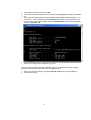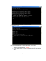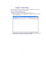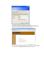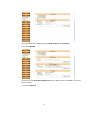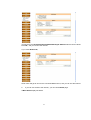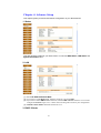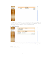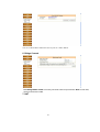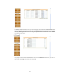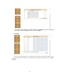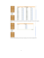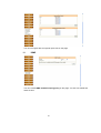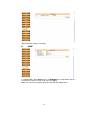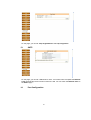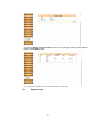
1
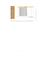
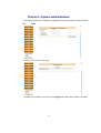
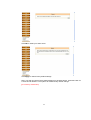
EC3805F Smart NAT Router Installation Guide www.edge-core.com Revision History Revision EC380F_001R001 EC380F_002R001 Date Change Description Preliminary Add introduction 04/28/2009 05/18/2009 2 CONTENTS SMART ROUTER USER’ S MANUAL ........................................................................................... REVISION HISTORY .................................................................................................................. 2 BEFORE YOU USE .................................................................................................................................4 UNPACKING ........................................................................................................................................... FEATURES ............................................................................................................................................. CHAPTER 1: OVERVIEW ........................................................................................................... 6 CHAPTER 2: SYSTEM REQUIREMENT AND INSTALLATION ..................................................... 8 System Requirement ...................................................................................................................................... 8 Connecting to ADSL Modem and Client PC .................................................................................................. 9 Setting up IP address of Host PC .................................................................................................................. 11 CHAPTER 3: QUICK SETUP..................................................................................................... 16 Using the Web-Based Manager ..................................................................................................... 16 CHAPTER 4: ADVANCE SETUP ............................................................................................... 21 1. Status ............................................................................................................................................................. 21 2. LAN................................................................................................................................................................. 21 3. DHCP Clients ................................................................................................................................................. 21 4. WAN Connection ........................................................................................................................................... 22 5. Bridge Convert ............................................................................................................................................... 22 6. NAT ................................................................................................................................................................ 23 7. Firewall ........................................................................................................................................................... 24 8. QOS ............................................................................................................................................................... 25 9. IGMP .............................................................................................................................................................. 28 10. SNMP ............................................................................................................................................................. 29 11. SNTP .............................................................................................................................................................. 30 12. Port Config ..................................................................................................................................................... 30 13. Vlan .................................................................................................................................................................... 14. System Logs .................................................................................................................................................. 31 CHAPTER 5: SYSTEM ADMINISTRATION ................................................................................ 33 15. Tool ................................................................................................................................................................ 33 3 Introduction Fiber-To-The-Home (FTTH) has always been an attractive option for Internet asccess. It has all the benefits of optical fiber. It provides a future-proof network, in that you do not have to go through the hassles of upgrading from ADSL to xDSL, or digital co-ax to digital wireless. It does not have to struggle with electromagnetic interference problems, and with no active “outside-plant” components, it offers the highest reliability. Moreover, it does not require electric power and is immune to lightning and other transients. These properties of fiber lead to the lowest possible power and operational costs, such as maintenance, provisioning and facilities planning. The EC3805F Media Converter is an ideal Customer Premises Equipment (CPE) for an FTTH system. The CPE has an embedded (no external plug/socket) 100BASE-FX full-duplex single-fiber single-mode cable connection that runs from the service provider’s central office (CO). The single-mode fiber connection can be run up to distances of 15 km from the CO. The CPE provides four standard 10/100BASE-TX RJ-45 Ethernet port for connecting to a customer’s PC, switch, or other network device using twisted-pair cable. 4 Features: Bridging Features Supports self-learning bridge specified in IEEE 802.1d Transparent Bridging Supports up to 4096 learning MAC addresses Transparent Bridging among 10/100 Mb Ethernet interface Supports IGMP Snooping Supports 802.1Q VLAN packet Supports one 100BaseFX port Routing Features NAT (Network Address Translation) / NPAT (Port Address Translation) ALGs (Application Level Gateways): such as NetMeeting, MSN Messenger,FTP, Quick Time, Real Player, VPN pass-through with multiple sessions, SIP, etc. Port Forwarding: the users can setup multiple virtual servers (e.g., Web, FTP, Mail servers) on user’s local network. DHCP Client/Server Time protocol can be used to get current time from network time server Support IP/Bridge QoS for prioritize the transmission of different traffic classes Supports IGMP Snooping and Proxy Support 802.1Q VLAN Tagging Supports one 100BaseFX port 5 Chapter 1: Overview This chapter provides you the description for the LEDs and connectors in the front and rear surface of the router. Before you use/install this router, please take a look at this information first. Package Contents Before you start to install the Switch, please verify your package that contains the following items: One smart NAT router One Power Adapter One User’s Manual Robber foot Note: If any of these items is found missing or damaged, please contact your local supplier for replacement. Physical Outlook Front Panel The following illustration shows the front panel of the NAT Smart Router: 6 LED Indicators The NAT Smart Router is equipped with several LEDs…….as described in the table below (from left to right): LED Power Color Status Green On Off LINK/ACT. Yellow On Off Flashing Description Power on Power off connection disconnection data transmission Rear Panel The following figure illustrates the rear panel of the NAT Smart Router: 7 Chapter 2: System Requirement and Installation System Requirement To access the NAT Smart Router via Ethernet, the host computer must meet the following requirements: Equipped with an Ethernet network interface. Have TCP/IP installed. Allow the client PC to obtain an IP address automatically or set a fixed IP address. With a web browser installed: Internet Explorer 5.x or later. The NAT Smat Router is configured with the default IP address of 192.168.1.254 and subnet mask of 255.255.255.0. Considering that the DHCP server is Enable by default, the DHCP clients should be able to access the Smart Router, or the host PC should be assigned an IP address of the same subnet and related subnet mask (for example, IP address of 192.168.1.100 and subnet mask of 255.255.255.0) first for initial configuration. After configuring the IP of host PC, you also can manage the Smart Router through a web-based manager. The ADSL Router manager uses the HTTP protocol via a web browser to allow you to set up and manage the device. 8 Connecting to ADSL Modem and Client PC Follow the steps below to connect the related devices. 1. Please attach one end of the Ethernet cable with RJ-45 connector to the LAN port of the ADSL Modem. 2. Connect the other end of the Ethernet cable to the WAN port of the Smart Router. (insert pic) 3. Attach one end of another Ethernet cable with RJ-45 connector to the LAN port of the Smart Router. (insert pic) 9 4. Connect the other end of the cable to the Ethernet port of the host PC. (insert pic) 5. Connect the supplied power adapter to the PWR port of your Smart Router, and plug the other end to a power outlet. (insert pic) 10 Setting up IP address of Host PC In the case the DHCP server function of the Smart Router is disabled or you want to configure the IP address of the host PC, please follow the steps below for installation. 1. Open the Start menu, point to Network and Dial-up Connections and click it. 2. Right-click the Local Area Connection icon to pull down a window and then click Properties. 3. The Local Area Network Properties window appears. On the General tab: highlight Internet Protocol (TCP/IP) and then click Properties. 11 4. The Internet Protocol (TCP/IP) Properties window appears. On the General tab: 1) For the case DHCP Server of Smart Router is enabled, enable Obtain an IP address automatically and click OK. 2) For the case DHCP Server of Smart Router is enabled or you want to set the IP address by yourself, enable Use the following IP address and fill in the IP address field with the address of the same subnet with Smart Router, for example, 192.168.1.100; the Subnet mask field with value 255.255.255.0 and the Default gateway field with the IP address of Smart Router (192.168.1.254) and then click OK. 12 After configuring the IP address of the host PC, you can check if the IP address is correctly configured by the following steps: 1. Open the Start menu, point to run and click it. 13 2. Type cmd in the text book and click OK. 3. A command window will show and in the window type ipconfig /all and then press enter key. 4. In the command window will show the IP address, Subnet Mask, Default Gateway…..etc. information. The IP address should be 192.168.1.xxx, xxx is a value other than 254 from 0 to 255, and the Subnet Mask should be 255.255.255.0 while the default gateway should be 192.168.1.254. 5. If the IP address of your PC is not correctly configured, please follow the steps described above to re-configure the IP address of your PC. You can further check the connection between your PC and the Smart Router by ping command. Following the steps below are for ping command. 1. Also in the command window, type ping 192.168.1.254 and then press enter key. 2. If the window shows: 14 then your PC and Smart Router are connected successfully. 3. If the window shows: then your PC and Smart Router are not connected correctly, you can check: 1) If the Ethernet cable between Smart Router and PC is correctly connected by checking if the link/ack LED is on. (insert pic) 2) If the IP address of the PC is correctly configured by following the steps described above. 15 Chapter 3: Quick Setup This chapter guides you through the steps to configure the basic features of your Smart Router, so that you can connect to the internet quickly. Using the Web-Based Manager After properly configuring your host PC, please proceed as follows: 1. Start your web browser and type 192.168.1.254, the default IP address of the Smart Router, in the URL field. 2. After connecting to the device, you will be prompted to enter username and password. By default, both the username and the password are admin. 16 3. 4. An example under Windows XP is shown as the left figure. After you login successfully, the system info page will appear. From now on, the Smart Router acts as a web server sending HTML pages/forms on your request. You can fill in these pages/forms and apply them to the Smart Router. To surf the internet, you have to configure wan connection first. Click the button WAN on the left menu, and the WAN connection page will appear. As below: 17 Then choose the wan connection type, PPPOE, Static IP, or Dynamic IP. If you chose PPPOE, you have to fix the Username/Password with your ADSL account. Click OK, and you can surf the internet. If you chose Static IP, 18 you have to fix the IP Address/Subnet Mask/Gateway IP Address with the correct values. Click OK, and you can surf the internet. If you chose Dinamic IP, smart router will get an IP from the connected DHCP server, and you can surf the internet. 5. If you can not access to the internet, you can check Status page: If Wan Status display like below: 19 Check the account, and configure by following the steps described above. Note: Make sure the validity of the account. 20 Chapter 4: Advance Setup This chapter guides you advanced features configuration of your Smart Router. 1. Status This page shows the status of your smart router. You can see WAN Status, LAN Status and System information here. 2. LAN (1) Fix the IP Address/Subnet Mask. (2) If you want to enable DNS Proxy, mark the check box, and click Apply. (3) If you want to enable DHCP Server function, mark the DHCP Server check box. You can also configure the IP Pool range (1-253). Smart router will assign IP to client as your configuration. (4) Limited Clients number should be fixed from 0 to 6. 3. DHCP Clients 21 This page shows the DHCP clients. If the client uses static IP, the type should be Static, and if the client uses obtain an IP address automatically, the type should be Dynamic. The list is timed refresh. If the entry is aging out, it will be cleared automatically. 4. WAN Connection The WAN Connection setup steps, you can refer Chapter 3: Quick Setup. Besides, you can configure static DNS list if you access the internet by method Static IP and Dynamic IP. 5. MAC Address Clone 22 You can set WAN MAC address the same as your PC’s MAC address. 6. Bridge Convert Mark Bridge Mode enable to convert your smart router as a pure switch. Note: In this case, router functions are invalid. 7. NAT 23 Fix Server IP with the device’s IP you want to support remote access. Internal Port should be the same with you opened on your device. External Port should be the port you access remotely. Port Type determinates which type of packet should be dealt with. Check Enable to make the entry valid. 8. Firewall This page is used to filter WAN destination IP. Fix the IP Address with the IP you want to filter, mark the Deny of the entry, then click OK. 24 This page is used to filter lan client MAC address. Fix the MAC with the mac address you want to filter, mark the Deny of the entry, then click Apply. 9. VLAN You can set VLAN Tag ID from 1 to 4095 for each port. The max VLAN group number is 16. Set VLAN ID to 0 means disable the VLAN group. After any change of settings, please click Apply. 10. QOS 25 This page is used to set QOS Mode and QOS Rule. Select the mode and rule you want to set, then click Apply. You can configure priority per port on this page, from low level to highest level. 26 You can configure priority per DSCP value (0 to 64) on this page, from low level to highest level. You can configure priority per vlan tag on this page, from low level to highest level. 27 You can set ingress rate and egress queue rate on this page. 11. IGMP You can choose IGMP disable/snooping/proxy on this page. You also can enable fast leave function. 28 IGMP status will display on this page. 12. SNMP To enable SNMP, select Enable option of SNMP Mode. Fix other blanks with the corresponding value you want to set, then click Apply. Note: The community and port should be consistent with SNMP client. 29 On this page, you can set Trap Target Address and Trap Target Port. 13. SNTP On this page, you can set 5 SNTP server here. Your smart router will update the Network Time automatically when internet connection is OK. You can check the Network Time on the Status page. 14. Port Configuration 30 You can set Speed and Flow control for each port on this page. Then the status should display on Port Status page. This page shows the link status and speed information of this router. 15. System Logs 31 This page shows system logs, such as reboot, clean, factory default setting logs. 32 Chapter 5: System Administration This chapter guides you to managing, upgrading and trouble shooting your Smart Router. 16. Tool Change your account on this page. Upgrade new firmware on this page. Click Upgrade and select the firmware to upgrade. 33 Click OK to restart your smart router. Click Apply to restore factory default settings. Note: You also can restore factory default settings by hardware button. Press the button for 5 seconds and release it. The system will restore factory default settings. (pic of factory reset button) 34