1
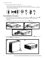
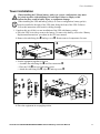
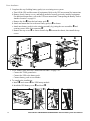
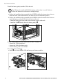
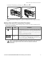
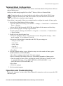
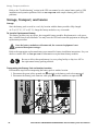
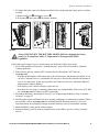
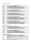
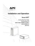
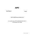
APC Smart-UPS® RT SURTA48XLBP/SURTA48XLBPJ External Battery Pack User Manual Introduction/Before Installation About this Manual The APC Smart-UPS® RT external battery pack (SURTA48XLBP or SURTA48XLBPJ) connects to the APC Smart-UPS RT uninterruptible power supply (SURTA1500XL and SURTA2000XL, or SURTA1500XLJ). Together these units provide extended protection against blackouts, brownouts, sags and surges reaching your computers, servers, and other sensitive electronic equipment. Illustrations are representative. Your configuration, including components and optional APC equipment, may be different from the models shown in this manual. The user manual is accessible from the supplied CD and the APC Web site, www.apc.com. Contact Information Refer to www.apc.com to contact APC or for additional information about this product. Safety Information Read the Safety Guide before you begin the installation, operate the battery pack, or perform equipment maintenance. Failure to comply with safety instructions could result in bodily injury or equipment damage. Warning To lighten the load, remove battery modules before installing equipment, or when transporting the equipment to another location. The equipment is heavy. Two people are required to lift the UPS or battery pack. Heavy Note Select a location sturdy enough to handle the weight of the equipment. The battery pack is shipped with the battery modules installed. Battery modules are shipped DISCONNECTED to be in compliance with U.S. Department of Transportation (DOT) regulations. Unpacking and Equipment Placement 1. Unpack the equipment. The packaging is recyclable; save it for reuse or dispose of it properly. 2. Inspect the equipment upon receipt. Notify the carrier and dealer if there is damage. 3. Check the package contents: – the battery pack and front bezel – a literature kit containing user manual, two clips, two stabilizing foot extensions with hardware, product documentation, warranty documentation, and safety information. Pre-installation Procedure 4. Place the battery pack where it will be used. – Ensure that air vents on the front and rear of the unit are not blocked. – Do not operate the battery pack where there is excessive dust or the temperature or humidity are outside the specified limits. 40°C 104°F 2.5 cm 95% 0% 2.5 cm Pre-installation Procedure 1. Once the battery pack is at the installation site, remove the top cover and battery modules to lighten the load and prepare the battery pack to be installed in a tower or rack-mount configuration. 2. To disengage the battery from the chassis, push the battery tabs inward. 3. Go to the installation procedures to install the UPS and battery pack as a tower (page 3) or in a rack-mount (page 5) configuration. 2 Smart-UPS RT SURTA48XLBP/SURTA48XLBPJ External Battery Pack User Manual Tower Installation Tower Installation Caution Note When installing the UPS and battery pack(s) as a tower configuration, they must be joined together with stabilizing feet and clips. Failure to comply to this instruction may result in bodily injury or equipment damage. When installing the UPS and battery pack(s) as a tower configuration, battery pack(s) must be installed to the right of the UPS when facing the front of the UPS. Failure to follow this instruction could result in cabling shortage. 1. Complete this step if this is a new installation of the UPS with battery pack(s). a. Place the UPS on its side to remove the battery. To remove the battery, refer to the “Battery Replacement Instructions” procedure in the UPS user manual. b. Remove the stabilizing feet and top cover . Retain removed components for reuse. x2 x2 c. Join the equipment together as shown. • Assemble the stabilizing feet and foot extensions . • Place the UPS on top of the battery pack. • Attach the stabilizing feet , clips , and top covers . x2 x4 x2 d. Place the equipment in an upright position. Smart-UPS RT SURTA48XLBP/SURTA48XLBPJ External Battery Pack User Manual 3 Tower Installation 2. Complete this step if adding battery pack(s) to an existing tower system. a. Turn Off the UPS and disconnect all equipment. Refer to the UPS user manual for instructions. b. Remove bezels, battery covers, and battery modules from all previously installed equipment. For additional instructions, refer to the UPS user manual and “Transporting the Battery Pack to Another Location” on page 10. c. Remove the feet from the last battery pack . d. Attach and mount the feet to the new battery pack(s) as shown. e. Attach new battery pack(s) to the existing assembly by joining the two assemblies and securing screws in the foot extensions . f. Remove the top covers as shown. Install clips between the chassis, then install the top covers. x2 x2 x2 x2 x2 3. Go to “Battery Pack and UPS Connection Procedure” on page 7 to: – Connect the TVSS ground wire. – Connect the UPS to the battery pack. – Connect battery packs to one another. 4. To complete the installation: a. Install and connect the UPS battery module. b. Install the UPS battery cover and bezel . 4 Smart-UPS RT SURTA48XLBP/SURTA48XLBPJ External Battery Pack User Manual Rack-mount Installation c. Install and connect the battery pack battery modules. d. Install the battery pack covers and bezel . 5. Go to “Terminal Mode Configuration” on page 9 to configure the UPS to recognize the battery pack(s). Rack-mount Installation 1. Complete this step if this is a new installation of the UPS with battery pack(s). a. Place the UPS on its side to remove the battery. To remove the battery, refer to the “Battery Replacement Instructions” procedure in the UPS user manual. b. Remove the stabilizing feet and top cover . Retain removed components for reuse. x2 x2 2. Complete this step if adding battery pack(s) to an existing rack-mount system. Before removing the UPS from the rack: ensure that the UPS is NOT connected to utility or battery power circuits; the UPS is turned OFF, and equipment is Caution disconnected from the UPS. a. When installing battery pack(s), ensure that the UPS is installed directly above the battery pack(s). b. If removal of the UPS is required, refer to “Transporting the UPS to Another Location” procedure in the UPS user manual. Smart-UPS RT SURTA48XLBP/SURTA48XLBPJ External Battery Pack User Manual 5 Rack-mount Installation 3. Install the battery pack(s) and the UPS in the rack. The UPS must be installed ABOVE the battery pack(s) when in a rack. Failure to follow this instruction could result in cabling shortage. Note a. Refer to the installation sheet contained in the SURTRK rail box for instructions on how to install the cleats, rack-mount brackets, and labels on the UPS and battery pack(s). b. Refer to the installation sheet contained in the SURTRK rail box for instructions on how to install the battery pack and UPS rails and chassis in the rack. • Install the battery pack rails in the lowest available u-space in the rack. • Install the UPS directly above the battery pack(s) . 4. Go to “Battery Pack and UPS Connection Procedure” on page 7 to: – Connect the TVSS ground wire. – Connect the UPS to the battery pack. – Connect battery packs to one another. 5. To complete the installation: a. Install and connect the UPS and battery pack battery modules. 6 Smart-UPS RT SURTA48XLBP/SURTA48XLBPJ External Battery Pack User Manual Battery Pack and UPS Connection Procedure b. Install the UPS and battery pack battery covers and bezels . 6. Go to “Terminal Mode Configuration” on page 9 to configure the UPS to recognize the battery pack(s). Battery Pack and UPS Connection Procedure The battery pack is equipped with the following connectors. Refer to the UPS user manual for UPS connector types and definitions. Connectors Caution Type Description TVSS screw The UPS and battery pack features a Transient Voltage Surge-suppression (TVSS) screw located on the rear panel, for connecting the ground cable on surge suppression devices such as telephone and network line protectors. NOTE: Prior to connecting the grounding cable, turn off the UPS and disconnect it from the utility power outlet. battery pack connector Smart-UPS RT battery packs provide extended run-time during power outages. A maximum of 10 battery packs can be used with the UPS. NOTE: See the APC Web site, www.apc.com for information on the battery pack, SURTA48XLBP or SURTA48XLBPJ. Prior to connecting the grounding cable, ensure that the UPS is NOT connected to utility or battery power circuits. See the UPS user manual for additional instructions. Smart-UPS RT SURTA48XLBP/SURTA48XLBPJ External Battery Pack User Manual 7 Battery Pack and UPS Connection Procedure 1. Connect the green/yellow ground wire(s) to the TVSS screw locations between the UPS and battery pack, or between battery packs as shown. TVSS GND TVSS GND TVSS GND 2. To connect the battery pack to the UPS and to connect battery packs to one another: a. Remove the UPS battery connector plate . b. Insert the adjacent battery pack connector cable plug into the connector receptacle on the UPS. c. If applicable, insert the battery pack connector cable plug into the connector receptacle on the adjacent battery pack. TVSS GND TVSS GND TVSS GND 8 Smart-UPS RT SURTA48XLBP/SURTA48XLBPJ External Battery Pack User Manual Terminal Mode Configuration Terminal Mode Configuration This configuration affects the accuracy of the runtime calculations that the UPS performs while running on battery power. Settings are made through supplied PowerChute® Business Edition or Terminal Mode. Note Terminal mode can only be used with the serial cable provided with the UPS. If using a USB cable, disconnect the USB cable from the UPS, and connect the serial cable to the UPS before using the terminal program. Shown below is an example of how to use terminal mode to configure the number of battery packs. 1. Exit the PowerChute Business Edition software. a. From the windows PC desktop, select START => Settings => Control Panel => Administrative Tools => Services. b. Select APC PCBE Server and APC PCBE Agent. Right click the mouse and select Stop. 2. Open a terminal program. Example: HyperTerminal From the computer desktop, select START => Programs => Accessories => Communication => HyperTerminal. 3. Double-click the HyperTerminal icon. a. Follow the prompts to choose a name and select an icon. Disregard the message, “...must install a modem,” if it is displayed. Click OK. b. Select the COM port that is connected to the UPS. The port settings are: • Bits per second - 2400 • data - bits 8 • parity - none • stop bit - 1 • flow control - none c. Press Enter. 4. Once the terminal window is open, follow these steps to set the number of battery packs (SURTA48XLBP or SURTA48XLBPJ): a. Press Enter to initiate terminal mode. Follow the prompts. b. Press 1 to modify UPS settings. Press e (or E) to modify the number of battery packs. c. Enter the number of battery packs, including the internal UPS battery (Number of packs: 1 = internal UPS battery, 2 = one SURTA48XLBP or SURTA48XLBPJ, 3 = two SURTA48XLBP or SURTA48XLBPJ, etc.) d. Press Enter. e. Follow the prompts. 5. Exit the terminal program. Operation and Troubleshooting Refer to the “Operation” section in the UPS user manual for instructions on how to operate the UPS and battery pack. Smart-UPS RT SURTA48XLBP/SURTA48XLBPJ External Battery Pack User Manual 9 Storage, Transport, and Service Refer to the “Troubleshooting” section in the UPS user manual to solve minor battery pack or UPS installation and operation problems. Refer to www.apc.com with complex battery pack or UPS problems. Storage, Transport, and Service Storage Store the battery pack covered in a cool, dry location with the battery modules fully charged. At 5° to 113° F (–15° to 45° C), charge the battery modules every six months. To Install a Replacement Battery This battery pack has easy-to-replace, hot-swappable battery modules. Replacement is a safe procedure, isolated from electrical hazards. You may leave the UPS and connected equipment on during the replacement procedure. Once the battery modules are disconnected, the connected equipment is not protected from power outages. Caution Refer to the appropriate replacement battery user manual for battery installation instructions. See your dealer or contact APC at www.apc.com for information on replacement battery modules. Pb Be sure to deliver the spent battery(s) to a recycling facility or ship it to APC in the replacement battery packing material. Pb Transporting the Battery Pack to Another Location Perform these steps before transporting the battery pack to another location. 1. Disconnect the green/yellow ground wire attached to the battery pack to be transported. 2. Disconnect the battery pack connector cable plug from the connector receptacle(s) . TVSS GND TVSS GND TVSS GND 10 Smart-UPS RT SURTA48XLBP/SURTA48XLBPJ External Battery Pack User Manual Storage, Transport, and Service 3. To lighten the load, remove the battery modules before transporting the battery pack to another location. a. Remove the bezel and battery covers . b. Disconnect and remove the battery modules. Service Caution Always DISCONNECT THE BATTERY MODULES before shipping the battery pack to be in compliance with U.S. Department of Transportation (DOT) regulations. If the battery pack requires service do not return it to the dealer. Follow these steps: 1. Review the problems discussed in “Troubleshooting” in the UPS user manual to eliminate common problems. 2. If the problem persists, contact APC Customer Service through the APC Web site, www.apc.com. – Note the model number of the battery pack, the serial number, and the date purchased. If you call APC Customer Service, a technician will ask you to describe the problem and attempt to solve it over the phone. If this is not possible, the technician will issue a Returned Material Authorization Number (RMA#). – If the battery pack is under warranty, repairs are free. – Procedures for servicing or returning products may vary internationally. Refer to the APC Web site, www.apc.com for country specific instructions. 3. Disconnect the battery for transport. See step 3 in “Transporting the Battery Pack to Another Location” on page 10. 4. Pack the battery pack and front bezel in its original packaging to avoid damage in transit. If this is not available, refer to www.apc.com for information about obtaining a new set. Never use Styrofoam beads for packaging. Damage sustained in transit is not covered under warranty. 5. Mark the RMA# on the outside of the package. 6. Return the battery pack by insured, prepaid carrier to the address given to you by Customer Service. Smart-UPS RT SURTA48XLBP/SURTA48XLBPJ External Battery Pack User Manual 11 Limited Warranty American Power Conversion (APC) warrants its products to be free from defects in materials and workmanship for a period of two years from the date of purchase. Its obligation under this warranty is limited to repairing or replacing, at its own sole option, any such defective products. To obtain service under warranty you must obtain a Returned Material Authorization (RMA) number from customer support. Products must be returned with transportation charges prepaid and must be accompanied by a brief description of the problem encountered and proof of date and place of purchase. This warranty does not apply to equipment that has been damaged by accident, negligence, or misapplication or has been altered or modified in any way. This warranty applies only to the original purchaser who must have properly registered the product within 10 days of purchase. EXCEPT AS PROVIDED HEREIN, AMERICAN POWER CONVERSION MAKES NO WARRANTIES, EXPRESSED OR IMPLIED, INCLUDING WARRANTIES OF MERCHANTABILITY AND FITNESS FOR A PARTICULAR PURPOSE. Some states do not permit limitation or exclusion of implied warranties; therefore, the aforesaid limitation(s) or exclusion(s) may not apply to the purchaser. EXCEPT AS PROVIDED ABOVE, IN NO EVENT WILL APC BE LIABLE FOR DIRECT, INDIRECT, SPECIAL, INCIDENTAL, OR CONSEQUENTIAL DAMAGES ARISING OUT OF THE USE OF THIS PRODUCT, EVEN IF ADVISED OF THE POSSIBILITY OF SUCH DAMAGE. Specifically, APC is not liable for any costs, such as lost profits or revenue, loss of equipment, loss of use of equipment, loss of software, loss of data, costs of substitutes, claims by third parties, or otherwise. Copyright Notice Entire contents copyright © 2004 by American Power Conversion Corporation. All rights reserved. Reproduction in whole or in part without permission is prohibited. APC, Smart-UPS, and PowerChute are registered trademarks of American Power Conversion Corporation. All other trademarks are the property of their respective owners. 990-1857 06/2004 *990-1857*