1
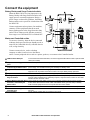
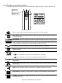
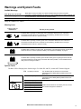
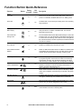
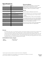
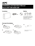
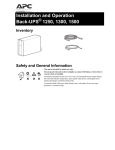
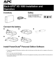
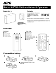
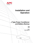
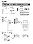
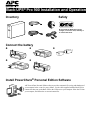
Back-UPS® Pro 900 Installation and Operation Inventory Safety (2) bu001a Do not install the Back-UPS in direct sunlight, in excessive heat, humidity, or in contact with fluids. Connect the battery bu055a bu057a bu059a bu060a bu058a Install PowerChute® Personal Edition Software APC PowerChute Personal Edition software provides automatic file saving and shutdown of your computer in the event of a power failure. Use the cable supplied with the Back-UPS to connect the data port on the Back-UPS to the USB port on your computer. Place the CD into your computer, and follow the on-screen instructions. Connect the equipment Battery Backup and Surge Protected outlets When the Back-UPS is receiving input power, the Battery Backup with Surge Protection outlets will supply power to connected equipment. During a power outage or other utility problems, the Battery Backup outlets receive power for a limited time from the Back-UPS. Connect equipment such as printers, fax machines, scanners, or other peripherals that do not need battery backup power to the Surge Protection Only outlets. These outlets provide full-time protection from surges even if the Back-UPS is switched OFF. bu130a Master and Controlled outlets To conserve electricity, when the device connected to Master Outlet goes into Sleep or Standby mode, or turns Off, the Controlled device(s) will shut down as well, saving electricity. Connect a master device, such as a desktop computer or audio/visual receiver to the Master outlet. Connect peripheral devices such as a printer, speakers, or a scanner to the Controlled outlets. USB and Serial Data port To use PowerChute Personal Edition, connect the supplied USB software cable or optional serial cable (not included). Telephone cable surge-protected Connect a telephone cable to the IN port, and connect a modem to the OUT port. ports Surge Protected outlets, These outlets are protected from electrical surges, and will disconnect from utility power during a controlled by the Master outlet power outage, or if the Master device goes into Sleep or Standby mode. Surge Protected outlets These outlets provide full-time surge protection, even when the unit is turned off. Connect equipment such as printers and scanners that do not require battery backup protection. AC power outlet Connect the unit to utility power, use the supplied power cord. Battery Backup outlets with During a power outage or other utility problems, these outlets provide power from battery. Connect critical equipment such as desktop computer, computer monitor, modem or other data sensitive devices into these outlets. Battery Backup outlet with Surge These outlets will supply battery power to the connected equipment during a power outage. Protection, controlled by the Power will be disconnected to these outlets if the Master device goes into Sleep or Standby Master outlet mode. Connect equipment such as a computer monitor to these outlets. Master outlet Connect the master device to this outlet, in most scenarios, this will be the main computer. Surge Protection In & Out Ethernet surge- protected ports Circuit breaker 2 Use an Ethernet cable to connect a cable modem to the IN port, and connect a computer to the OUT port. Use to reset the system after an overload or short circuit. Back-UPS Pro 900 Installation and Operation Operation Power-Saving Function To conserve electricity, configure the Back-UPS to recognize a Master device, such as a desktop computer or an A/V receiver, and Controlled peripheral devices, such as a printer, speakers, or a scanner. When the Master device goes into Sleep or Standby mode, or is switched OFF, the Controlled device(s) will be switched off as well, saving electricity. Enable the Power-Saving function. Press and hold MUTE and DISPLAY simultaneously for two seconds. The Back-UPS will beep to indicate that the feature is enabled. The leaf icon on the display will illuminate. Disable the Power-Saving function. Press and hold MUTE and DISPLAY simultaneously for two seconds. The Back-UPS will beep to indicate that the feature is disabled. The leaf icon on the display will darken. Setting the threshold. The amount of power used by a device in Sleep or Standby mode varies between devices. It may be necessary to adjust the threshold at which the Master outlet signals the Controlled outlets to shut down. 1. Ensure a master device is connected to the Master outlet. Put that device into Sleep or Standby mode, or turn it OFF. 2. Press DISPLAY and MUTE simultaneously and hold for six seconds, until the leaf icon flashes three times and the Back-UPS beeps three times. 3. The Back-UPS will now recognize the threshold level of the Master device and save it as the new threshold setting. Power-Saving Display The display interface can be configured to be continuously illuminated, or to save energy, it can be configured to darken after a period of inactivity. 1. Full Time Mode: Press and hold DISPLAY for two seconds. The display will illuminate and the Back-UPS will beep to confirm the Full-Time mode. 2. Power-Saving Mode: Press and hold DISPLAY for two seconds. The display will darken and the Back-UPS will beep to confirm the Power-Saving mode. While in Power-Saving Mode, the display will illuminate if a button is pressed, it then darkens after 60 seconds of no activity. Unit sensitivity Adjust the sensitivity of the Back-UPS to control when it will switch to battery power; the higher the sensitivity, the more often the Back-UPS will switch to battery power. 1. Ensure the Back-UPS is connected to utility power, but is OFF. 2. Press and hold the POWER button for six seconds. The LOAD CAPACITY bar will flash on and off, indicating that the Back-UPS is in programming mode. 3. Press POWER again to rotate through the menu options. Stop at selected sensitivity. The Back-UPS will beep to confirm the selection. Low sensitivity 156-300 Vac Medium sensitivity (Default) High sensitivity 176-294 Vac 176-288 Vac Input voltage is extremely low or The Back-UPS frequently switches to The connected equipment is high. (Not recommended for battery power. sensitive to voltage fluctuations. computer loads.) Back-UPS Pro 900 Installation and Operation 3 Front Panel Buttons and Display Interface Use the three buttons on the front panel of the Back-UPS and the display interface to configure the Back-UPS. Front panel Mute button Power On/Off button Display button Display interface bu044a bu002a On Line—The Back-UPS is supplying conditioned utility power to connected equipment Power-Saving—Master and Controlled outlets are enabled, saving power when the master device goes into sleep or standby mode Load Capacity—The load is indicated by the number of sections illuminated, one to five. Each bar represents 20% of the load. Battery Charge—The battery charge level is indicated by the number of sections illuminated. When all five blocks are illuminated, the Back-UPS is at full charge. When one block is filled, the Back-UPS is near the end of its battery capacity, the indicator will flash and the Back-UPS will beep continuously. Overload—The power demand from the load has exceeded the capacity of the Back-UPS. Event—The event counter shows the number of events that occurred that caused the Back-UPS to switch to on-battery operation. Automatic Voltage Regulation—The Back-UPS can compensate for high or low input voltage. When illuminated, the Back-UPS is compensating for low input voltage. When illuminated, the Back-UPS is compensating for high input voltage. Input voltage. Output voltage. System Faults—The system has a fault. The fault number will illuminate on the display interface. See “System Faults” on page 5. Mute—If the line through the speaker icon is illuminated, the audible alarm has been turned off. Replace Battery—The battery is not connected or is nearing the end of its useful life. Replace the battery. On Battery—The Back-UPS is supplying battery backup power to the connected equipment, it will beep four times every 30 seconds. 4 Back-UPS Pro 900 Installation and Operation Warnings and System Faults Audible Warnings Back-UPS is running on battery. You should consider saving any work in progress. Low battery condition and battery run-time is very low. Promptly save any work in progress, exit all open applications, and shut down the operating system. Battery Backup outputs are overloaded. Four Beeps Every 30 Seconds Continuous Beeping Continuous tone Chirps for 1 Minute every 5 hours Battery fails the automatic diagnostic test and should be replaced. Warning Icons If these icons are illuminated... This may be the problem. The Back-UPS is operating on utility power, but is overloaded. Disconnect one of the items connected to the Back-UPS. If the Overload icon stops flashing, the Back-UPS is no longer overloaded and will continue to operate normally. The Back-UPS is operating on battery power, but is overloaded. Disconnect one of the items connected to the Back-UPS. If the Overload icon stops flashing, the Back-UPS is no longer overloaded and will continue to operate normally. The Back-UPS is operating on utility power, but the battery is not functioning properly. Contact APC Customer Service to order a replacement battery. See “Replacement Battery” on page 8. The Back-UPS is operating on battery power and the battery power is getting low. Shut down all connected equipment to avoid losing an unsaved data. When possible, connect the Back-UPS to utility power to recharge the batter. System Faults The Back-UPS will display these fault messages. For faults F01 and F02, contact APC Technical Support. F01 On-Battery Overload bu088a F02 On-Battery Output Short F03 F04 F05 F06 F07 F08 F09 Turn the Back-UPS off. Disconnect non-essential equipment from the Battery Backup outlets and the turn Back-UPS on. Turn the Back-UPS off. Disconnect non-essential equipment from the Battery Backup outlets and the turn Back-UPS on. On-Battery Xcap Overload Clamp Short Charge Fault Faults F03-F09 cannot be corrected by the user, contact Relay Welding APC Technical Support for assistance. Temperature Fan Fault Internal Fault Back-UPS Pro 900 Installation and Operation 5 Function Button Quick-Reference Function Timing Button (seconds) UPS Status Description Power Power On 0.2 Off Press POWER to start receiving input utility power. If A/C input power is not available, the Back-UPS will run on battery power. Power Off 2 On The Back-UPS is not receiving input utility power, but is providing surge protection. 0.2 On Verify the status or condition of the Back-UPS. The LCD will illuminate for 60 seconds. 2 On The LCD will illuminate and the Back-UPS will beep to confirm the Full-Time mode. The LCD will darken and the Back-UPS will beep to confirm the Power-Saving mode. While in Power-Saving Mode, the LCD will illuminate if a button is pressed, then darkens after 60 seconds of no activity. 0.2 On Disable any audible alarms caused by an event. General Status Enable/ Disable 2 On Enable or disable the audible alarms. The Mute icon will illuminate and the Back-UPS will beep one time. The Mute function will not activate unless the Back-UPS is operating on battery power. Sensitivity 6 Off Master/Controlled outlet Enable/Disable 2 On Master/Enable Threshold Calibration 6 On The Load Capacity icon will blink, indicating that the Back-UPS is in programming mode. Use the POWER button to scroll through Low, Medium, and High, stop at selected sensitivity. The BackUPS will beep to confirm selection. See Configuration for details. The leaf icon will darken indicating that the Master Outlet feature is disabled or illuminate to indicate the Master Outlet feature is enabled. The Back-UPS will beep once. While calibrating the threshold setting, the device connected to the Master Outlet should be turned off or placed in Standby or Sleep mode. Upon completion, Power-Saving icon will flash 3 and beep 3 times. Self-Test (manual) 6 On The Back-UPS will perform a test of the internal battery. Note: This will happen automatically when the Back-UPS is turned ON. Event Reset 0.2 On When the Event screen is visible, press and hold DISPLAY, then press POWER, to clear the utility failure event counter. Fault Reset 2 Fault 6 Back-UPS Pro 900 Installation and Operation Display Status Inquiry Full-Time/PowerSaving mode Mute Event Specific After a fault has been identified, press POWER to remove the visual indication and return to standby status. Troubleshooting Problem Back-UPS will not switch on. Possible Cause The Back-UPS is not connected to utility power. The circuit breaker has been tripped. The internal battery is not connected. The utility input voltage is out of range. The Back-UPS does not Ensure that essential equipment is not provide power during a utility plugged into a SURGE ONLY outlet. power outage. The Back-UPS is operating on The plug has partially pulled out of the wall battery power, while connected outlet, the wall outlet is no longer receiving to utility power. utility power, or the circuit breaker has been tripped. The Back-UPS is performing an automatic self test. The utility input voltage is out of range, the frequency is out of range, or the waveform is distorted. The Back-UPS does not Battery Backup outlets may be fully or provide the expected amount of improperly loaded. backup time. The battery was recently discharged due to a power outage and has not fully recharged. The battery has reached the end of its useful life. The battery has reached the end of its useful The REPLACE BATTERY indicator is illuminated. life. The OVERLOAD indicator is The equipment connected to the Back-UPS illuminated. is drawing more power than the Back-UPS can provide. The SYSTEM FAULT indicator is There is an internal fault. illuminated, all the front panel indicators are flashing. Power is not supplied to some outlets. Power to the Controlled outlets has intentionally been turned off. The Controlled outlets are not The Master Outlet threshold may be supplying power, even though incorrectly set. the Master device is not in sleep mode. Corrective Action Ensure that the Back-UPS is securely connected to an AC outlet. Disconnect non-essential equipment from the Back-UPS. Reset the circuit breaker. Re-connect equipment one item at a time. If the circuit breaker is tripped again, disconnect the device that caused the trip. Connect the battery. Adjust the transfer voltage and sensitivity range. Disconnect equipment from the SURGE ONLY outlet and re-connect to a Battery Backup outlet. Ensure that the plug is fully inserted into the wall outlet. Ensure that the wall outlet is receiving utility power by checking it with another device. No action is necessary. Adjust the transfer voltage and sensitivity range. Disconnect non-essential equipment from the Battery Backup outlets and connect the equipment to SURGE ONLY outlets. Charge the battery cartridge for 16 hours. Replace the battery. Replace the battery. Disconnect non-essential equipment from the Battery Backup outlets and connect the equipment to SURGE ONLY outlets. Determine which internal fault message is displayed by matching the number displayed on the LCD with the corresponding Fault Message (see System Faults) and contact APC Technical Support. Confirm that the correct peripherals are connected to Controlled outlets. If this feature is not desired, disable the Power-Saving Master and Controlled outlets. Adjust the threshold when the Master outlet signals the Controlled outlets to shut down. Back-UPS Pro 900 Installation and Operation 7 Specifications t Model BR900GI VA 900 VA Maximum Load 540 W Nominal Input Voltage 230 V Online Input Voltage Range 176 - 294 V Automatic Voltage Regulation (188-216) +11.2% (252-282) -11.2% Replacement Battery The battery cartridge typically lasts 3 to 6 years, a shorter period if subjected to frequent outages or elevated temperatures. Battery replacement part for Back-UPS Pro 900 is APCRBC123. Please recycle spent battery cartridges. Service If the Back-UPS arrived damaged, notify the carrier. 50/60 Hz ± 1 Hz If the Back-UPS requires service, do not return it to the dealer. On-battery Waveshape Step-approximated sine-wave Typical Recharge Time 8 hours 1. Consult the Troubleshooting section to eliminate common problems. Transfer Time 10 ms, maximum 2. If the problem persists, go to http://www.apc.com/support/. Operating Temperature 0 to 40C (32 to 104F) Storage Temperature -15 to 45C (5 to 113F) Unit Dimensions 25 × 10 × 38.2 cm (9.84 × 3.93 × 15.0 in) Unit Weight 10.7 kg (23.6 lbs) Interface Serial, USB On-Battery Runtime Go to: www.apc.com EMI Classification CE, C-Tick, KETI Approvals CE, TUV-GS, GOST, A-Tick, KETI, TISI Frequency Range 3. If the problem still persists, contact APC Technical Support. Have the Back-UPS model number, serial number and date of purchase available. Be prepared to troubleshoot the problem with an APC Technical Support representative. If this is not successful, APC will issue a Return Merchandise Authorization (RMA) number and a shipping address. Warranty The standard warranty is three (3) years from the date of purchase, valid in European Community. For all other regions, the standard warranty is two (2) years from the date of purchase. APC’s standard procedure is to replace the original unit with a factory reconditioned unit. Customers who must have the original unit back due to the assignment of asset tags and set depreciation schedules must declare such a need at first contact with an APC Technical Support representative. APC will ship the replacement unit once the defective unit has been received by the repair department, or cross-ship upon the receipt of a valid credit card number. The customer pays for shipping the unit to APC. APC pays ground freight transportation costs to ship the replacement unit to the customer. APC Worldwide Customer Support Internet http://www.apc.com Worldwide +1 888 272-3858 Customer support and warranty information is available at the APC Web site, www.apc.com. © 03/2010 APC by Schneider Electric. All trademarks are owned by Schneider Electric Industries S.A.S., American Power Conversion Corporation, or their affiliated companies. 990-3837A 3/2010