1
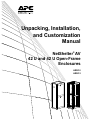
Unpacking, Installation, and Customization Manual NetShelter® AV 42 U and 42 U Open-Frame Enclosures AR3810 AR3812 Contents Introduction...................................................................... 1 Safety Warnings and Cautions....................................... 1 Unpacking the Enclosure................................................ 2 Component Identification ............................................... 3 Removing and Reinstalling Side Panels, Roof, and Doors ................................................................................ 5 Side Panels . . . . . . . . . . . . . . . . . . . . . . . . . . . . . . . . . . . . . . . . . . . . . .5 Roof . . . . . . . . . . . . . . . . . . . . . . . . . . . . . . . . . . . . . . . . . . . . . . . . . . . .5 Doors . . . . . . . . . . . . . . . . . . . . . . . . . . . . . . . . . . . . . . . . . . . . . . . . . . .6 Enclosure Installation ..................................................... 7 Moving the Enclosure . . . . . . . . . . . . . . . . . . . . . . . . . . . . . . . . . . . . . .7 Leveling the Enclosure . . . . . . . . . . . . . . . . . . . . . . . . . . . . . . . . . . . . .8 Joining Enclosures . . . . . . . . . . . . . . . . . . . . . . . . . . . . . . . . . . . . . . . .9 Reversing the Front Door . . . . . . . . . . . . . . . . . . . . . . . . . . . . . . . . . .10 Securing the Enclosure . . . . . . . . . . . . . . . . . . . . . . . . . . . . . . . . . . .13 Grounding the Enclosure . . . . . . . . . . . . . . . . . . . . . . . . . . . . . . . . . .14 Completing the Installation . . . . . . . . . . . . . . . . . . . . . . . . . . . . . . . .15 Equipment Installation .................................................. 16 Adjusting the Vertical Mounting Rails. . . . . . . . . . . . . . . . . . . . . . . .16 Installing Equipment . . . . . . . . . . . . . . . . . . . . . . . . . . . . . . . . . . . . . .19 Cable Routing and Cable Management ....................... 20 Roof . . . . . . . . . . . . . . . . . . . . . . . . . . . . . . . . . . . . . . . . . . . . . . . . . . .20 Vertical 0 U Accessory Channels. . . . . . . . . . . . . . . . . . . . . . . . . . . .21 NetShelter AV 42 U Enclosure Unpacking, Installation, and Customization Manual i Accessories ................................................................... 22 Specifications ................................................................ 26 APC Limited Factory Warranty..................................... 27 ii NetShelter AV 42 U Enclosure Unpacking, Installation, and Customization Manual Introduction The American Power Conversion (APC®) NetShelter® AV Enclosure is a high-quality enclosure for storage of industry-standard (EIA-310), 19-inch rack-mount hardware, which includes servers, voice, data, networking, security, audio-visual, and APC power protection equipment. • The NetShelter AV 42 U Enclosure (AR3810) is a complete enclosure with all panels: front door, rear doors, side panels, and roof. • The NetShelter AV 42 U Open-Frame Enclosure (AR3812) is a frame-only enclosure for which you can purchase side panels, roof, and doors as required for your unique needs. (See “Component Identification” on page 3.) Various accessories are mentioned in this manual. For complete details on any accessory, see the APC Web site, www.apc.com. To quickly find a part on the APC Web site, enter the part number in the Search field. For additional information about this product, see the product page on the APC Web site, www.apc.com Safety Warnings and Cautions Observe all Warnings and Cautions in this manual, plus the following. Tip Hazard: This equipment is easily tipped. Use extreme caution when unpacking or moving. Heavy: Use at least two people to unpack the enclosure. Warning: To avoid damage or injury, do not use the roof as a walkway. NetShelter AV 42 U Enclosure Unpacking, Installation, and Customization Manual 1 Unpacking the Enclosure Disclaimer American Power Conversion is not responsible for damage sustained during reshipment of this product. Receiving inspection Inspect the package and contents for shipping damage, and make sure that all parts were sent. Report any damage immediately to the shipping agent. Report missing contents, damage, or other problems immediately to APC or your APC reseller. Please Recycle The shipping materials are recyclable. Save them for later use, or dispose of them appropriately. Procedure 1. Move the shipping pallet to a firm, level surface in an open area. Inspect for visible signs of shipping damage. If you detect shipping damage, contact APC Customer Support using the contact information on the back cover of this manual. 2. See the label on the packaging to determine where to cut the wrapping. Using sturdy shears or a utility knife, carefully remove the plastic stretch wrap surrounding the enclosure. 3. Remove the four cardboard corner protectors. 4. Remove and retain the two pallet-mounting brackets with mounting hardware that anchor the enclosure to the shipping pallet. Use a 13-mm wrench (not provided). Note: Save the pallet-mounting brackets if you plan to bolt the enclosure to the floor. 5. With one person on each side of the enclosure, carefully roll it toward the rear of the pallet until the rear casters clear the back edge of the pallet. Continue to slide the enclosure until the rear casters touch the floor. 6. While one person carefully tips the enclosure slightly away from the pallet, have the other person pull the pallet away from the enclosure. Set the enclosure gently on its casters. Warning: Use caution when moving an empty enclosure on its casters; the enclosure may be unstable when pushed or pulled from the side. Push the enclosure from the front or back when moving it on its casters. For extra stability, load 158 kg (350 lbs) of equipment into the bottom of the enclosure before moving it on its casters. 2 NetShelter AV 42 U Enclosure Unpacking, Installation, and Customization Manual Component Identification Enclosure Enclosure frame Roof with conduit knockouts and cable access (AR7213)† Side brace Removable rear split doors (AR7100)† Adjustable vertical 0 U accessory channel Key for doors and side panels† Pallet/bolt-down bracket Removable side panels with locks (AR7306)† Adjustable leveling feet Removable and reversible front door (AR7000A)† Casters Hardware bag (see page 4) Adjustable vertical mounting rails † Options for the NetShelter AV 42 U Open-Frame Enclosure (AR3812) NetShelter AV 42 U Enclosure Unpacking, Installation, and Customization Manual 3 Hardware bag contents TORX® T30/#2 Phillips wrench (1) 4 #10-32 screws (60) M5 x 12 screws (4) 7-mm hole plugs (4) 5-mm hole plugs (5) Frame handle cutout cover (2) NetShelter AV 42 U Enclosure Unpacking, Installation, and Customization Manual Removing and Reinstalling Side Panels, Roof, and Doors na2591a Side Panels Roof ns1724a ×2 NetShelter AV 42 U Enclosure Unpacking, Installation, and Customization Manual 5 Doors Note: Doors self-align on hinge pins when properly reinstalled. ns1750a 1. With the door at a 90-degree angle to the front of the enclosure, position the door over the hinge pins (). ns1751a 2. Use slight pressure to pull the door away from enclosure; then lower the door. ns1752a 3. Connect the ground wire. 6 NetShelter AV 42 U Enclosure Unpacking, Installation, and Customization Manual Enclosure Installation Moving the Enclosure Caution: To avoid damaging the enclosure and causing a tip hazard, make sure the leveling feet are up before moving the enclosure. Casters. The enclosure can be moved on its casters with up to 1021 kg (2,250 lbs) of equipment installed. Tip Hazard: Use caution when moving an empty enclosure on its casters. Push the enclosure from the front or back only; the enclosure may be unstable if pushed or pulled from the side. For extra stability, load 158 kg (350 lbs) of equipment into the bottom of the enclosure before moving it on its casters. ns1596a Eye bolts. The enclosure can be lifted using eye bolts with up to 567 kg (1,250 lbs) of equipment installed. Use M10 eye bolts with a shoulder rated for 181 kg (400 lbs). NetShelter AV 42 U Enclosure Unpacking, Installation, and Customization Manual 7 Leveling the Enclosure Required tools: Phillips screwdriver Level 13-mm open-ended wrench Warning: The leveling feet at the corners provide a stable base if the floor is uneven, but they cannot compensate for a badly sloped surface. ns1632a To adjust the leveling feet after equipment has been installed, use a 13-mm open-ended wrench (not provided). 8 NetShelter AV 42 U Enclosure Unpacking, Installation, and Customization Manual Joining Enclosures Enclosures can be joined with or without side panels installed to provide for alignment and some stability. Caution: Joining enclosures provides limited stability to the enclosures. 1. Make sure the leveling feet are down. 2. Remove the front and rear doors. 3. Choose between 24-in centers or 600-mm centers (see the detail view below). If enclosures are joined on 24-in centers, APC offers baying trim (AR7600) to cover the gap between the enclosures. The trim can be installed after the units are joined together. 4. Align the enclosures and join them using one M5 x 12 flat-head screw (provided in the hardware bag) per bracket—two brackets for the front and two brackets for the rear. 5. Reinstall the doors. (See “Moving the Enclosure” on page 7.) ns1594a 600 mm 24 in NetShelter AV 42 U Enclosure Unpacking, Installation, and Customization Manual 9 Reversing the Front Door If desired, you can reverse the front door so the door opens from the opposite side of the enclosure. 1. Remove the APC nameplate from the front door. ns1626a 2. Remove the grounding wire using the TORX wrench (provided). ns1613a 3. Remove the door handle assembly. 10 NetShelter AV 42 U Enclosure Unpacking, Installation, and Customization Manual 4. Remove the door. ns1607a 5. Remove the hinges from the frame. ns1609a 6. Reinstall the hinges on the opposite side of the enclosure. ns1605a 7. Remove screws securing the hinges in the door frame. NetShelter AV 42 U Enclosure Unpacking, Installation, and Customization Manual 11 8. Reposition and reinstall hinge. ns1606a 9. Reinstall the door. 10.Reinstall the door handle assembly with the washer and latch oriented as shown. The washer is rotated 90 degrees from its original orientation (). 11. Reinstall the grounding wire with star washer. The star washer must be installed under the grounding wire (see step 2). ns1615a 12.Reinstall the APC nameplate on the front door. 12 NetShelter AV 42 U Enclosure Unpacking, Installation, and Customization Manual Securing the Enclosure For additional stabilization, secure the enclosure to the floor. Use fastener locations on the outside or inside of the enclosure, and choose from the accessories shown below. Accessory SKU Description Pallet/boltdown brackets (provided with the enclosure; not available as a purchased part) Attaches to rack and floor internally or externally to provide additional stability without blocking cable access. NetShelter SX stabilizer plate AR7700 Attaches externally to the rack and floor to provide additional stability. Bolt-down kit AR7701 Attaches to rack and floor internally or externally to provide additional stability without blocking cable access. With the appropriate mounting hardware, meets UBC Zone-4 seismic requirements. ns1753a To secure the enclosure to the floor, use the fastener locations on the outside of the enclosure, as shown, or use the fastener locations on the inside of the enclosure. NetShelter AV 42 U Enclosure Unpacking, Installation, and Customization Manual 13 Grounding the Enclosure Each enclosure should be grounded directly to the building ground using one of the designated grounding locations (two M6 threaded inserts) at the top or bottom of the enclosure. • Use a Common Bonding Network Jumper kit (for example, Listed [KDER] Panduit RGCBNJ660PY or equivalent). • Use paint-piercing washers between ground terminal and enclosure frame or remove paint on frame under ground terminals per NEC NFPA 70 Article 250.12. • Torque screws to 6.9 N-m (60 in-lb). ns1617a • Do not ground one enclosure to another enclosure in a cascading style. 14 NetShelter AV 42 U Enclosure Unpacking, Installation, and Customization Manual Completing the Installation ns1616a Install plugs and covers included in the hardware bag, as needed. NetShelter AV 42 U Enclosure Unpacking, Installation, and Customization Manual 15 Equipment Installation Installing equipment in the NetShelter AV Enclosure may require adjusting the vertical mounting rails to the correct depth for your equipment before installing equipment. Adjusting the Vertical Mounting Rails ns1621a Audio-visual equipment is secured to the vertical mounting rails in the NetShelter AV Enclosure. The vertical mounting rails are adjustable to accommodate the depth of your AV equipment. The vertical mounting rails come factory-installed for use with AV equipment that has a depth of 508 mm (20 in). The vertical mounting rails can be adjusted to be as close together as 191 mm (7.5 in) or as far apart as 680 mm (26.8 in), when the vertical 0 U accessory channels have been removed. SKU Description NetShelter SX recessed rail kit AR7503 Allows you to install another set of rails in either the top or bottom of the enclosure. This allows equipment with two different depths to be installed in the enclosure. ns1634a Accessory 16 NetShelter AV 42 U Enclosure Unpacking, Installation, and Customization Manual Perform the following steps to adjust a vertical mounting rail: Warning: To avoid personal injury or damage to the enclosure, perform this procedure without any equipment installed on the vertical mounting rails. 1. Unlock the vertical mounting rail. Use the TORX wrench (provided in the hardware bag) to loosen the screw—but do not remove. NetShelter AV 42 U Enclosure Unpacking, Installation, and Customization Manual 17 2. Move the vertical mounting rail to the desired location. 3. Check alignment. Note symbols (circle, triangle, and square) visible through the set of three holes at each location, and make sure the symbols match. If not, realign the vertical mounting rail. – Vertical mounting rails adjust in 6-mm (1/4-in) increments. ns1624a 4. Lock the top, middle, and bottom of the vertical mounting rail. ns1623a – Make sure the vertical mounting rails on both sides of the enclosure are adjusted to the same depth. Verify that the same symbols are visible. 18 NetShelter AV 42 U Enclosure Unpacking, Installation, and Customization Manual Installing Equipment Warning: To prevent the enclosure from tipping over after equipment installation: • Make sure you have secured the enclosure before installing equipment. • Load the heaviest equipment first toward the bottom of the enclosure to prevent the enclosure from becoming top-heavy. • Do not extend equipment on sliding rails until you have installed three or more pieces of similar-sized equipment or until you have installed the stabilizer plate or bolt-down brackets. • Do not extend more than one piece of equipment on sliding rails at a time. Before getting started, make sure you have adjusted the vertical mounting rails as needed. To install rack-mount equipment in the NetShelter AV Enclosure: 1. Review the equipment manufacturer’s installation instructions. 2. Locate the top and bottom U-space on the vertical mounting rails. Every third hole on the mounting rails is numbered to indicate the middle of a U-space. A U-space consists of one of these numbered holes and one hole directly above and below it, as shown. 7 6 5 ns1595a 1U 3. Install the equipment using the #10-32 screws (provided). See the manufacturer’s instructions provided with the equipment for additional details. NetShelter AV 42 U Enclosure Unpacking, Installation, and Customization Manual 19 Cable Routing and Cable Management Roof Knockout 20 Quantity Conduit Size (EMT) Knockout Size 2 1 in 1.375 in 4 1.25 in 1.734 in 2 2 in 2.469 in 3 0.5 in 0.875 in 3 0.75 in 1.109 in 4 - 0.625 in NetShelter AV 42 U Enclosure Unpacking, Installation, and Customization Manual ns1629a ns1628a ns1694a Four removable roof-top panels () provide knockouts of varying dimensions for conduit. For larger cable volumes, remove the panels entirely. Brush strips () cover cutouts in the front and rear of the roof panel which also provide openings for cable routing. Vertical 0 U Accessory Channels The vertical 0 U accessory channels provide toolless mounting capabilities for APC Rack Power Distribution Units (Rack PDU) and APC cable management accessories (see page 22). The vertical 0 U accessory channels also provide tie-off locations for cables. Accessory SKU Description NetShelter SX 42 U Narrow Vertical 0 U Cable Organizer AR7511 Depending on the position of the vertical mounting rails and the vertical 0 U accessory channels, additional vertical 0 U accessory channels may be installed. The narrow vertical cable organizer complements the standard vertical cable organizer by offering additional cable management options. The narrow channel can be used in the front of the enclosure to mount fiber cable spools and vertical cable managers or can be used in the middle of the enclosure for cable tie off. In addition, keyholes are provided to mount one vertical Rack PDU per organizer. ns1754a ns1631a The vertical 0 U accessory channels can be located in the enclosure anywhere along the side braces. The standard position for the vertical 0 U accessory channels is in the rear of the enclosure, but they can be positioned anywhere along the side braces like the vertical mounting rails (see “Adjusting the Vertical Mounting Rails” on page 16). NetShelter AV 42 U Enclosure Unpacking, Installation, and Customization Manual 21 Accessories Accessory SKU Description Copper busbar AR8395 20 U copper busbar for NetShelter AV enclosures. Tooless installation in vertical 0 U accessory channel or vertical mounting rail. Shelf AR8125 Adjustable, reversible shelf. 115 VAC roof fan tray ACF505 Includes four fans to pull heated air out of the enclosure. Toolless installation. NetShelter AV 2 U rack fan panel ACF600 Includes four fans for cooling AV equipment. Accessories include a temperature controller (ACF601), vent panel (ACAC40001), and vent panel with temperature display (ACAC40000). 22 NetShelter AV 42 U Enclosure Unpacking, Installation, and Customization Manual Accessory SKU Description Top mount conduit access adapter AR7215 Allows option to route cable into side of unit. Includes knock out panels for conduit. Toolless installation. Toolless hook and loop cable manager (Qty. 10) AR8621 Includes ten 457-mm (18-in) hook and loop black cable straps that install in the square holes in the vertical 0 U accessory channel or the vertical mounting rail. Cable containment brackets (Qty. 6) AR7710 Contains cables along the vertical 0 U accessory channel. Installs without tools. Vertical cable organizer AR8442 Installs in a vertical 0 U accessory channels to facilitate vertical cable management and eliminate cable stress. Takes up zero U of space within the enclosure. Consists of two pieces of equal size that, when stacked, span the height of a 42-U enclosure. Can be used in any APC enclosure. Toolless installation. Cable management rings (Qty. 5 large and 5 small) AR8113A Fastens cables to posts, mounting rails, or braces. NetShelter AV 42 U Enclosure Unpacking, Installation, and Customization Manual 23 Accessory SKU Description 19-inch horizontal cable organizers AR8602 (1 U) Routes cables horizontally on the front or back of the 19-inch EIA enclosure. AR8600 (2 U) AR8601 (2 U double sided) AR8603 (2 U high density) AR8425A (1 U) 24 19-inch 2-U horizontal cable organizer pass-through AR8428 Routes cables horizontally or front-to-rear. 19-inch 1-U cable passthrough with brush strip AR8429 Assists with containing air in the enclosure and providing an aesthetic solution for cable routing. Zero-U accessory mounting bracket (Qty. 2) AR7711 Zero U multi-purpose accessory mounting bracket for 1 U and 2 U equipment, including Rack PDUs. Vertical cable organizer, center rear mount AR7505 Routes cables or attaches rack PDUs vertically in the center of the back of the enclosure under the brush strips. Installs toollessly in a 42-U or 48-U enclosure. ns1145c AR8426A (2 U) NetShelter AV 42 U Enclosure Unpacking, Installation, and Customization Manual Description Vertical fiber organizer AR8443A The vertical fiber organizer provides a method to manage fiber cabling within an enclosure and mounts toollessly into the vertical 0 U accessory channel. 42 U/48 U Baying Trim AR7600 Fills the gap between the enclosures, providing finished look. ns1755a ns1156a SKU ns1163a Accessory NetShelter AV 42 U Enclosure Unpacking, Installation, and Customization Manual 25 Specifications Specifications NetShelter AV 42 U Enclosure (AR3810) NetShelter AV 42 U OpenFrame Enclosure (AR3812) Height 1991 mm (78.40 in) 1991 mm (78.40 in) Width 600 mm (23.62 in) 600 mm (23.62 in) Depth 825 mm (32.48 in) 753 mm (29.60 in) Net weight 119.3 kg (263 lb) 71.7 kg (158 lb) Total open area (front door) 593 018 mm2 (919.18 in2) n/a Total open area (rear door) 669 276 mm2 (1,037.38 in2) n/a Open area per U (front door) 14 129 mm2 (21.90 in2) n/a Open area per U (rear door) 15 935 mm2 (24.70 in2) n/a Perforation pattern percentage 69% n/a Percent of perforated area (front) 66% n/a Percent of perforated area (rear) 74% n/a Clearance (for wiring between front door and vertical rail) 60.96 mm (2.40 in) n/a Weight rating: static load† 1361 kg (3,000 lb) 1361 kg (3,000 lb) Weight rating: rolling 1021 kg (2,250 lb) 1021 kg (2,250 lb) Weight rating: shipping‡ 567 kg (1,250 lb) 567 kg (1,250 lb) † 26 Lower the leveling feet if the static weight is over 1020.58 kg (2,250 lb). NetShelter AV 42 U Enclosure Unpacking, Installation, and Customization Manual APC Limited Factory Warranty The limited warranty provided by American Power Conversion (APC®) in this Statement of Limited Factory Warranty applies only to Products you purchase for your commercial or industrial use in the ordinary course of your business. Terms of Warranty American Power Conversion warrants its products to be free from defects in materials and workmanship for a period of five years from the date of purchase. Its obligation under this warranty is limited to repairing or replacing, at its sole discretion, any such defective products. This warranty does not apply to equipment that has been damaged by accident, negligence, or misapplication or has been altered or modified in any way. Repair or replacement of a defective product or part thereof does not extend the original warranty period. Any parts furnished under this warranty may be new or factoryremanufactured. Non-transferable Warranty This warranty applies only to the original purchaser who must have properly registered the product. Product may be registered at http://www.warranty.apc.com. Exclusions APC shall not be liable under the warranty if its testing and examination disclose that the alleged defect in the product does not exist or was caused by end user’s or any third person’s misuse, negligence, improper installation or testing. Further APC shall not be liable under the warranty for unauthorized attempts to repair or modify wrong or inadequate electrical voltage or connection, inappropriate on-site operation conditions, corrosive atmosphere, repair, installation, start-up by non-APC designated personnel, a change in location or operating use, exposure to the elements, Acts of God, fire, theft, or installation contrary to APC recommendations or specifications or in any event if the APC serial number has been altered, defaced, or removed, or any other cause beyond the range of the intended use. THERE ARE NO WARRANTIES, EXPRESS OR IMPLIED, BY OPERATION OF LAW OR OTHERWISE, OF PRODUCTS SOLD, SERVICED OR FURNISHED UNDER THIS AGREEMENT OR IN CONNECTION HEREWITH. APC DISCLAIMS ALL IMPLIED WARRANTIES OF MERCHANTABILITY, SATISFACTION AND FITNESS FOR A PARTICULAR PURPOSE. APC EXPRESS WARRANTIES WILL NOT BE ENLARGED, DIMINISHED, OR AFFECTED BY AND NO OBLIGATION OR LIABILITY WILL ARISE OUT OF, APC RENDERING OF TECHNICAL OR OTHER ADVICE OR SERVICE IN CONNECTION WITH THE PRODUCTS. THE FOREGOING WARRANTIES AND REMEDIES ARE EXCLUSIVE AND IN LIEU OF ALL OTHER WARRANTIES AND REMEDIES. THE WARRANTIES SET FORTH ABOVE CONSTITUTE APC SOLE LIABILITY AND PURCHASER’S EXCLUSIVE REMEDY FOR ANY BREACH OF SUCH WARRANTIES. APC WARRANTIES RUN ONLY TO PURCHASER AND ARE NOT EXTENDED TO ANY THIRD PARTIES. IN NO EVENT SHALL APC, ITS OFFICERS, DIRECTORS, AFFILIATES OR EMPLOYEES BE LIABLE FOR ANY FORM OF INDIRECT, SPECIAL, CONSEQUENTIAL OR PUNITIVE DAMAGES, ARISING OUT OF THE USE, SERVICE OR INSTALLATION, OF THE PRODUCTS, WHETHER SUCH DAMAGES ARISE IN CONTRACT OR TORT, IRRESPECTIVE OF FAULT, NEGLIGENCE OR STRICT LIABILITY OR WHETHER APC HAS BEEN ADVISED IN ADVANCE OF THE POSSIBLY OF SUCH DAMAGES. SPECIFICALLY, APC IS NOT LIABLE FOR ANY COSTS, SUCH AS LOST PROFITS OR REVENUE, LOSS OF EQUIPMENT, LOSS OF USE OF EQUIPMENT, LOSS OF SOFTWARE, LOSS OF DATA, COSTS OF SUBSTITUANTS, CLAIMS BY THIRD PARTIES, OR OTHERWISE. NO SALESMAN, EMPLOYEE OR AGENT OF APC IS AUTHORIZED TO ADD TO OR VARY THE TERMS OF THIS WARRANTY. WARRANTY TERMS MAY BE MODIFIED, IF AT ALL, ONLY IN WRITING SIGNED BY AN APC OFFICER AND LEGAL DEPARTMENT. Warranty Claims Customers with warranty claims issues may access the APC worldwide customer support network by visiting http://www.apc.com/support. Select your country from the country selection pull-down menu. Open the Support tab at the top of the web page to obtain contact information for customer support in your region. APC Worldwide Customer Support Customer support for this or any other APC product is available at no charge in any of the following ways: • Visit the APC Web site to access documents in the APC Knowledge Base and to submit customer support requests. – www.apc.com (Corporate Headquarters) Connect to localized APC Web sites for specific countries, each of which provides customer support information. – www.apc.com/support/ Global support searching APC Knowledge Base and using e-support. • Contact the APC Customer Support Center by telephone or e-mail. – Local, country-specific centers: go to www.apc.com/support/contact for contact information. For information on how to obtain local customer support, contact the APC representative or other distributors from whom you purchased your APC product. © 2010 APC by Schneider Electric. APC, the APC logo, and NetShelter are owned by Schneider Electric Industries S.A.S., American Power Conversion Corporation, or their affiliated companies. All other trademarks are property of their respective owners. 990-3702A 6/2010