1
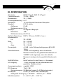
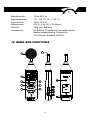
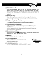
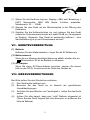
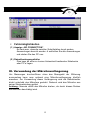
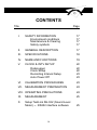
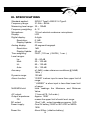
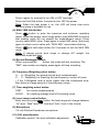
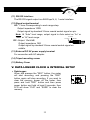
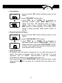
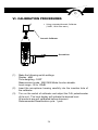
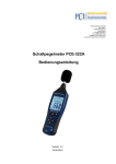
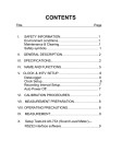
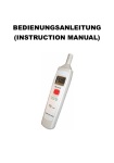
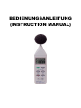
BEDIENUNGSANLEITUNG
(INSTRUCTION MANUAL)
DATA LOGGER SOUND LEVEL METER
INHALTSVERZEICHNIS
Titel
Seite
I.
SICHERHEITSINFORMATIONEN
Sicherheitssymbole
2
2
II.
ALLGEMEINE BESCHREIBUNG
2
III.
SPEZIFIKATION
3
IV.
FUNKTIONEN
4
V.
UHR UND EINSTELLUNGEN
7
VI.
KALIBRIERUNG
8
VII. GERÄTEVORBEREITUNG
9
VIII. MESSVORBEREITUNGEN
9
IX.
MESSUNG
10
X.
Softwareeinstellung TestLink SE-322
10
XI.
Verwendung der Mikrofonverlängerung
15
1
DATA LOGGER SOUND LEVEL METER
I. SICHERHEITSINFORMATIONEN
Lesen Sie bitte sorgsam die folgenden Informationen, bevor Sie mit den
Messungen beginnen.
Benutzen Sie das Messgerät nur in der beschriebenen Form,
anderenfalls erlischt die auf das Gerät gewährleistete Garantie.
Umweltbedingungen
§ Relative Feuchtigkeit max. = 90% rH
§ Arbeitstemperaturbereich = 0…+ 40 °C.
Wartung & Reinigung
§ Reparaturarbeiten am Gerät sollten nur durch den Hersteller
durchgeführt werden.
§ Halten Sie bitte as Gerät sauber und in trockenem Zustand.
Das Gerät unterliegt den allgemein gültigen Normen und Standards
(IEC651 Typ2, ANSI S1.4 Typ2) und ist CE-zertifiziert.
II. ALLGEMEINE BESCHREIBUNG
Das Datenspeicher-Schallpegelmeter SL 322 verfügt über einen internen
Datenspeicher für 32000 Werte. Immer, wenn Sie den “REC”-Knopf
drücken und nach der Messung wieder den “REC”-Knopf, dann wird ein
Datensatz in den Speicher geschrieben. Mittels der RS232 –
Schnittstelle können die Messwerte zum PC Übertragen werden.
2
DATA LOGGER SOUND LEVEL METER
III. SPEZIFIKATION
Standards:
IEC651 Type2, ANSI S1.4 Type2
Frequenzbereich :
31.5Hz ~ 8KHz
Messbereich :
30 ~ 130dB
Wichtung/Bewertung : A / C
Mikrophon:
1/2 inch Electret Kondensor Mikrophon
Display1 :
LCD, 4-stellig
Auflösung:
0.1dB
Werteerneuerung: 0.5 s
Display2 :
50 Segment Bargraph
Resolution:
1dB
Werteerneuerung: alle 50 ms
Zeitliche Bewertung: FAST ( 125 ms ), SLOW ( 1 sec. )
Messbereiche:
Lo:
30 – 80 dB
Med:
50 – 100 dB
Hi:
80 – 130 dB
Auto:
30 – 130 dB
Genauigkeit:
±1.5dB ( unter Referenzbedingungen @ 94 dB,
1KHz )
Alarmfunktionen:
“OVER” wird angezeigt, wenn der aktuelle
Messwert höher als der gewählte Messbereich ist
“UNDER” wird angezeigt, wenn der aktuelle
Messwert niedriger als der gewählte Messbereich
ist
MAX/MIN-Wert:
Hold-Funktion für den Kleinst- u. Höchstwert
AC-Ausgang:
1 Vrms / bezogen auf den Maximalwert des
gewählten Messbereiches)
Ausgangsimpedanz : ungefähr 100Ω
DC-Ausgang:
10mV / dB
Stromversorgung : 9V-Batterie (typisch für 50 Betriebsstunden)
AC-Adapter:
9 VDC ( 8-15VDC Max, Netzadapter)
Anliegende Versorgung: > 30mADC Stecker: pin → Masse
Arbeitstemperatur:
0 ...+40 °C ( 32 ... +104 °C )
3
DATA LOGGER SOUND LEVEL METER
Arbeitsfeuchte:
Lagertemperatur:
Lagerfeuchte:
Dimensionen:
Gewicht:
Accessories:
10 bis 90% rH
-10 ... 60 °C ( 14 ... 140 °C )
10 bis 75%rH
275 (L) × 64 (W) × 30 (H)mm
285g (inkl. Batterie)
9V Batterie, Tragetasche, Schraubendreher,
Bedienungsanweisung. Windschutz,
3.5V-Stecker, Software, RS-232
IV. NAME AND FUNCTIONS
9
•
1
2
3
6
A
C
SETUP
4
7
FAST
SLOW
CLOCK
INTV
REC
LEVEL
9V BATTERY
NEDA 1604 6F22 006P
CAL
MAX
MIN
PLEASE READ
MANUAL FOR SAFETY
OUTPUT
RS-232
8
Lo = 30
Med= 50
Hi = 80
Auto= 30
DC 9V
5
80 dB
100 dB
130 dB
130 dB
OPEN
POWER-UP OPTIONS
4
DATA LOGGER SOUND LEVEL METER
(1) Windschutz
Wenn Sie bei Windgeschwindigkeit > 10m/s messen, verwenden Sie
bitte den Windschutz auf dem Mikrofon
(2) Display
Symbol
MAX
MIN
FAST
SLOW
dBA
dBC
Funktion
Maximalanzeige
Minimalanzeige
Überbereichsanzeige
Unterbereichsanzeige
Schnelle Antwort
Langsame Antwort
A-Bewertung
C-Bewertung
Bereichswahl
Batterie “schwach”
Unterbereich 20dB
(3) Betrieb
Der (1) schaltet das Gerät und die Hintergrundbeleuchtung an und
aus.
Drücken Sie die Taste einmal, um das Gerät ein- o. auszuschaltenhalten Sie die
Taste einen Moment gedrückt, um
Hintergrundbeleuchtung ein oder auszuschalten.
Halten Sie die Taste ca. 3s lang gedrückt, um das Gerät
abzuschalten.
Anmerkung: Beim Einschalten wird der zur Verfügung stehende
Speicherplatz angezeigt.
5
DATA LOGGER SOUND LEVEL METER
(4) MAX / MIN Halte-Taste
Durch Drücken dieser Taste wird nur der Max-Wert angezeigt. Der
aktuelle Wert ist nur noch durch die Bargraph-Anzeige zu sehen.
Durch weiteres Drücken der Max/Min-Taste wird nur der Min-Wert
angezeigt. Um diesen Modus zu deaktivieren, halten Sie die Taste 2s
lang fest.
(5) Datalogger-Taste
Wenn Sie diese Taste einmal drücken, beginnt das Gerät mit der
Aufzeichnung. Ein weiteres Drücken stoppt die Datenaufzeichnung.
(6) Frequenz-Bewertungs-Taste
A: A-Bewertung für allgemeine Messungen
C: C-Bewertung zur Messung im niederfrequenten Bereich
(7) Taste für zeitliche Bewertung
FAST, (schnell): für normale Messungen und zur Erfassung von
Schallspitzen
SLOW, (langsam): für die Messung des Durchschnitts-Pegels bei
stark wechselnden Messwerten
(8) Bereichs-Kontroll-Taste
Immer, wenn Sie dies
Taste drücken, wechselt der Messbereich
zwischen “Lo”, “Med”, “Hi” und “Auto” Level.
(9) Mikrofon
1/2 inch Electret Kondensor Mikrofon
(10) CAL-Potentiometer
Wird zur Kalibrierung des Gerätes benutzt
(Abschnitt Kalibrierung).
(11) RS-232 Schnittstelle:
RS-232 – Signalausgang: 9600 Baud N, 8, 1, seriell.
6
DATA LOGGER SOUND LEVEL METER
(12) Signalausgabe
AC: 1 Vrms, jeweils anliegend beim Maxwert eines jeden
Messbereiches
(verwendet
wird
zur
Übertragung
ein
Standard-Koaxialkabel 3,5 mm)
Bemerkung: Im “Auto” Level-Bereich müssen Sie “Lo” oder “Med”
oder “Hi” – Bereichswahl vorgeben.
DC: 10mV/dB
Ausgangsimpedanz 1 KΩ
(verwendet wird zur Übertragung ein Standard-Koaxialkabel 3,5
mm)
(13) Externer DC 9V-Eingang für Adapter-Spannungsversorgung
(14) Gewindebohrung zur Montage eines Stativs
(15) Batteriefachdeckel
V. UHR UND EINSTELLUNGEN
§ DataLogger:
1. Wenn Sie die “REC”-Taste einmal drücken,
beginnt die Aufzeichnung. Wenn Sie die
Taste wieder drücken, wird die Aufzeichnung
gestoppt.
2. Wenn Sie die gespeicherten Daten löschen
möchten, schalten Sie das Gerät aus,
drücken und halten Sie den “REC”-Schalter
zusammen mit dem Ein-Schalter für 5
Sekunden. Dann erscheint “CLR” und
“SURE” auf dem Display.
§ Clock Setup :
1: Drücken u. halten sie die “A/C” – Taste und
schalten Sie das Gerät ein.
2: Drücken Sie die “MAX MIN”(clock)-Taste:
3: Drücken Sie die "REC" ▲-Taste oder die "LEVEL"
▼ – Taste, um den nächsten Menüpunkt
auszuwählen. Die Auswahlreihenfolge ist “year :
7
DATA LOGGER SOUND LEVEL METER
month : day : hour : minute” (Jahr, Monat, Tag,
Minute). Dann drücken Sie die “MAX MIN”(clock) –
Taste noch einmal, um den Vorganz zu beenden.
Aufnahmeeinstellungen:
1: Drücken u. halten Sie die “A/C” – Taste und
schalten das Gerät ein:
2: Wählen Sie “FAST/SLOW"(INTV):
3: Drücken Sie "REC" ▲ oder "LEVEL" ▼ um die
jeweilige Einstellung vorzunehmen. Ebenso für
“FAST/SLOW " (INTV) und noch einmal
“FAST/SLOW” (INTV), um die Einstellungen zu
beenden. Wenn Sie den Vorgang abbrechen
möchten, schalten Sie das Gerät einfach ab.
Auto Power Off:
Standardmäßig schaltet sich das Gerät nach30 min ab. Diese
Funktion lässt sich abschalten. Drücken und Halten Sie die
“FAST/SLOW” – Taste, schalten Sie das Gerät ein und die autom.
Abschaltung ist ausgeschaltet.
VI. KALIBRIERUNG
§
Unter Verwendung eines
additionalem Kalibrators ( 94dB,
1KHz Sinuswelle )
Additionaler Kalibrator
A
C
SETUP
FAST
SLOW
INTV
REC
LEVEL
Schraubendreher
RS-232
CLOCK
CAL
MAX
MIN
OUTPUT
80 dB
100 dB
130 dB
130 dB
DC 9V
Lo = 30
Med= 50
Hi = 80
Auto= 30
POWER-UP OPTIONS
8
DATA LOGGER SOUND LEVEL METER
(1) Stellen Sie das Gerät wie folgt ein: Display = dBA, zeitl. Bewertung =
FAST, Messmodus: MAX MIN Mode- Funktion ausstellen,
Messbereich: 50 … 100dB
(2) Stecken Sie das Gerät mit der Mikrofonspitze in die Öffnung des
Kalibrators.
(3) Schalten Sie die Kalibrierfunktion ein und justieren Sie das Gerät
mittels der Potentiometerschraube auf exakt 94 dB ein (Anzeigewert
im Display). Allgemein: Das Gerät ist werksseitig kalibriert – eine
Nachkalibrierung ist je nach Einsatzzweck sinnvoll.
VII . GERÄTEVORBEREITUNG
(1) Batterie
Entfernen Sie den Batteriedeckel u. legen Sie die 9V Batterie ein.
(2) Batterietausch
Wenn die zur Messung benötigte Spannung abfällt, erhalten Sie ein
Warnzeichen. Es ist die Batterie zu tauschen.
(3) AC Adapter
Wenn Sie einen AC-Strom-Adapter benutzen, stecken Sie diesen
bitte an den DC9V- Anschluss an der Seite des Gerätes an.
VIII. MESSVORBEREITUNGEN
Bei Wind sollten Sie den Windschirm aufsetzen.
(1) Das Gerät sollte kalibriert sein.
(2) Benutzen Sie das Gerät nur im Bereich der spezifizierten
Umweltbedingungen.
(3) Schützen Sie das Mikrofon vor Feuchtigkeit u. halten Sie das Gerät
sauber.
(4) Achten Sie bitte darauf, dass eine “volle” Batterie eingesetzt ist
(Wenn Sie das Gerät längere Zeit nicht benutzen, so entfernen Sie
bitte die Batterie)
9
DATA LOGGER SOUND LEVEL METER
IX. MESSUNG
(1) Schalten Sie das Gerät ein und wählen Sie die von Ihnen
gewünschten Parameter und Einstellungen aus. Standardmäßig wird
die A-Bewertung verwendet, um dem menschlichen Hörempfinden
nahe zu kommen.
(2) Halten Sie das Messgerät in Richtung der Schallquelle
(3) Wenn Sie die Min-Max-Hold-Funktion angewählt haben, halt das
Gerät diese Werte fest. Drücken Sie die MAX-MIN-Taste
2 Sekunden fest, um die “alten” Werte aus dem Display zu löschen.
X. Softwareeinstellung TestLink SE-322
Ÿ
Das Link-Paket beinhaltet:
1.) 80mm CD-ROM
2.) RS232 Verbindungskabel
Ÿ
Systemvoraussetzungen:
Windows 95 oder Windows 98
Ÿ
Ÿ
Ÿ
Hardwarevoraussetzungen:
PC oder Notebook mit Pentium 90MHz oder höher, 32 MB RAM,
Min. 5 MB verfügbarer Festplattenspeicher zur Installation.
Installation:
1. Alle Anwendungen schließen. Schieben Sie die Diskette 1 in das
Laufwerk
2. Betätigen Sie die “Start”-Schaltfläche u. wählen Sie “Run”. Geben
Sie ein: A:\SETUP und drücken Sie “OK”. Die Dateien werden
dann auf Ihre Festplatte kopiert.
Haupt-Menü
File | Open - … öffnet Dateien von der Diskette
Save – Speichert die Bildschirmdaten auf der Diskette
Print – Druckt die aktuelle Bildschirmoberfläche aus
Printer Setup – Sie können den Drucker auswählen
File | Exit: Beendet das Programm.
View | Control Panel: Beim … Öffnung dieses Fensters können
10
DATA LOGGER SOUND LEVEL METER
Sie die Messung “online” beobachten
View | Real-Time Graph: Hiermit können Sie sich in Echtzeit eine
grafische Darstellung der Messungen ansehen
Real Time Data | Run – Hiermit starten Sie die Darstellung
der Messwerte
Stop – Hiermit stoppen Sie die Echtzeitdarstellung der
Messwerte
DataLogger: Hiermit können Sie gesammelte Daten aufrufen
Output To Graph – Hiermit können Sie die Werte grafisch
anzeigen
Graph
Schaltflächen
- Anzeigen oder Verdecken von Statistik1
- Anzeigen oder Verdecken von Statistik2
- Cursor
- Das Drücken dieser Schaltfläche verwandelt den Cursor in ein
Kreuz – mit dem Kreuz können Sie Markierungen vornehmen
- Das Drücken dieser Schaltfläche verwandelt den Cursor in ein
“I”-Zeichen
- Farbgrafik
- Graustufen-Grafik
11
DATA LOGGER SOUND LEVEL METER
Sie können den schwarzen Pfeil zum “zoomen” benutzen. Bei
“Doppel-Klicken” auf die Grafik öffnen Sie die Dialog-Funktion. Hier
können Sie Grafikeinstellungen nach Ihren Wünschen vornehmen.
Durch Drücken der rechten Maus-Taste erhalten Sie ein Schnell-Menü.
DataLogger
Wenn Sie das Gerät mit einem PC verbunden haben drücken Sie
(oder Über die Auswahl im Hauptmenü “Datenlogger”), mit dem
Schallpegelmeter gespeicherte Daten zum PC zu Übertragen. Sie
erhalten kontinuierliche Informationen über den Fortgang des
Übertragungsprozesses. (Sollten Sie eine Fehlermeldung erhalten,
drücken Sie erneut “Datenlogger”) Nachdem die Daten übertragen
wurden, wird auf der linken Seite angezeigt, wie viele Datensätze
Übertragen wurden (auch Startzeit, Sammelzeit usw.).
Beispiel folgend:
12
DATA LOGGER SOUND LEVEL METER
Durch Anklicken eines Datensatzes holen Sie ihn sich auf den Bildschirm
§
Tutorial – Online - Schnellstart
(1.) Aufnahme von Daten in Echtzeit in Wellenform
1. Schalten Sie das Gerät ein und verbinden Sie es mit dem PC
2. Starten Sie das SE322- Programm
3. Nun werden die Messdaten am Gerät parallel auf dem
Bildschirm angezeigt
4. Drücken Sie
5. Drücken Sie
um die Darstellung in Echtzeit zu starten
um die Darstellung zu stoppen
(2.) Wie speichert man die Echtzeit-Daten ab?
1. Drücken Sie auf die Grafik, die Sie speichern möchten und
wählen Sie dann “File | Save” aus dem Hauptmenü aus oder
klicken Sie auf das
- Zeichen.
13
DATA LOGGER SOUND LEVEL METER
2. Sie erhalten dann einige Speichermöglichkeiten zur Auswahl
(Dateiname, Format usw.). Die gewonnenen Daten können
auch in anderen Programmen, wie Microsoft Excel, geöffnet
werden (ebenfalls die Grafiken).
(3.) Wie lädt und speichert man Datensätze, die mit der
Datenlogger-Funktion des Messgerätes erfasst und im Gerät
abgespeichert sind?
1. Schalten Sie das Gerät ein
2. Verbinden Sie das Gerät mit dem PC
3. Starten Sie das SE322-Programm
4. Wählen Sie die Funktion “Datenlogger” aus dem Menü
an oder drücken Sie auf die
- Schaltfläche (die
Daten werden Übertragen)
14
DATA LOGGER SOUND LEVEL METER
§
Fehlermöglichkeiten
(1.) Anzeige „NO CONNECTION“
Es kann sein, dass die seriellen Schnittstellen durch andere
Anwendungen benutzt werden à schließen Sie alle Anwendungen
und starten Sie den PC neu.
(2.) Datenübertragungsfehler
Dies kann an einer zu kurzen Antwortzeit bestimmter Notebooks
oder PC’s liegen.
XI. Verwendung der Mikrofonverlängerung
Um Messungen durchzuführen ohne das Messgerät der Witterung
auszusetzen kann man optional eine Mikrofonverlängerung käuflich
erwerben. Zur Verwendung dieser Verlängerung wird die Rändelmutter
direkt unterhalb des Mikrofons gedreht. Dadurch wird das Mikrofon aus
seiner Steckverbindung gelöst
Achtung: Niemals direkt das Mikrofon drehen, da durch dieses Drehen
das Mikrofon beschädigt wird.
15
DATA LOGGER SOUND LEVEL METER
CONTENTS
Title
Page
I.
SAFETY INFORMATION
Environment conditions
Maintenance & Clearing
Safety symbols
17
17
17
17
II.
GENERAL DESCRIPTION
17
III.
SPECIFICATIONS
18
IV.
NAME AND FUNCTIONS
19
V.
CLOCK & INTV SETUP
DataLogger
Clock Setup
Recording Interval Setup
Auto Power Off
22
22
22
23
23
VI.
CALIBRATION PROCEDURES
23
VII. MEASUREMENT PREPARATION
24
VIII. OPERATING PRECAUTIONS
24
IX.
MEASUREMENT
25
X.
Setup TestLink SE-322 (Sound Level
Meter) — RS232 interface software
25
16
DATA LOGGER SOUND LEVEL METER
I. SAFETY INFORMATION
Read the following safety information carefully before attempting to
operate or service the meter.
Use the meter only as specified in this manual; otherwise, the protection
provided by the meter may be impaired.
Environment conditions
§ Altitude up to 2000 meters
§ Relatively humidity 90% max.
§ Operation Ambient 0 ~ 40¡C
Maintenance & Clearing
§ Repairs or servicing not covered in this manual should only be
performed by qualified personnel.
§ Periodically wipe the case with a dry cloth. Do not use abrasives or
solvents on this instruments.
Safety symbols
Comply with EMC
When servicing, use only specified replacement parts.
II. GENERAL DESCRIPTION
Thank you for using our Data Logger Sound Level Meter. To ensure that
you can get the most from it, we recommend that you read and follow
the manual carefully before use.
This unit conforms to the IEC651 type2, ANSI S1.4 Type2 for Sound
Level Meters.
This Data Logger Sound Level Meter internal memory can keep up to
32000 records.(Note 1.)
It uses RS232 interface to perform bi-directional communication with PC.
Note1:
Every time you press “REC” button to start recording data and press “REC” button again to
stop recording, there will be a data set in memory, you can store as many data sets as you
want unit memory is full.
17
DATA LOGGER SOUND LEVEL METER
III. SPECIFICATIONS
Standard applied:
Frequency range:
Measuring level range:
Frequency weighting:
Microphone:
Display:
Digital display:
Resolution:
Display Update:
Analog display:
Resolution:
Display Update:
Time weighting:
Level ranges:
Lo:
Med:
Hi:
Auto:
Accuracy:
Dynamic range:
Alarm function:
MAX/MIN hold:
AC output:
Output impedance:
FS:
DC output:
Power supply:
Power life:
IEC651 Type2, ANSI S1.4 Type2.
31.5Hz ~ 8KHz
30 ~ 130dB
A/ C
1/2 inch electret condenser microphone
LCD
4 digits
0.1dB
0.5 sec.
50 segment bargraph
1dB
50 mS
FAST ( 125 ms ), SLOW ( 1 sec. )
30 – 80 dB
50 – 100 dB
80 – 130 dB
30 – 130 dB
±1.5dB ( under reference conditions @ 94dB,
1KHz )
100 dB
“OVER” is when input is more than upper limit of
range.
“ UNDER ” is when input is Less than lower limit
of range.
Hold readings the Maximum and Minimum
Value.
1 Vrms at FS ( full scale ).
Approx. 100Ω
means the upper limit of each level range.
10mV / dB , output impedance approx. 1KΩ
One 9V battery, 006P or IEC 6F22 or NEDA
1604.
About 50hrs ( alkaline battery )
18
DATA LOGGER SOUND LEVEL METER
AC adapter:
Supply current :
Socket:
Voltage 9 VDC ( 8-15VDC Max )
> 30mADC
pin → Ground
Casing → Positive
External Diameter → 3.5mm
Internal Diameter → 1.35mm
Electromagnetic Compatibility:
RF field = 3V/m
Total accuracy = specified accuracy + 0.5dB
Operation temperature: 0 to 40°C ( 32 to 104°C )
Operation humidity:
10 to 90%RH
Storage temperature:
-10 to 60°C ( 14 to 140°C )
Storage humidity:
10 to 75%RH
Dimensions:
275 (L) ×64 (W) ×30 (H)mm
10.8 (L) ×2.5 (W) ×1.2 (H)inch
Weight:
285g ( including battery )
Accessories:
9V battery, carrying case, Screwdriver,
Instruction manual. Windscreen, 3.5ψ plug,
software, RS-232 cable.
IV. NAME AND FUNCTIONS
9
•
1
2
3
6
A
7
REC
LEVEL
Lo = 30
Med= 50
Hi = 80
Auto= 30
9V BATTERY
NEDA 1604 6F22 006P
CAL
INTV
8
RS-232
FAST
SLOW
80 dB
100 dB
130 dB
130 dB
PLEASE READ
MANUAL FOR SAFETY
OUTPUT
MAX
MIN
CLOCK
DC 9V
5
C
SETUP
4
OPEN
POWER-UP OPTIONS
19
DATA LOGGER SOUND LEVEL METER
(1) Windscreen
If you operate at wind speed over 10m/sec, please put protective
accessories in front of the microphone.
(2) Display
FUNCTION
SYMBOL
LCD
MAX
MIN
4 digits
Maximum indication
Minimum indication
Over range
Under range
Fast response
Slow response
A-Weighting
C-Weighting
Range Indicate
Low-Battery
Under range 20dB
Auto Level range selective
Recording Datalogger
Memory full
Auto Power OFF active
FAST
SLOW
dBA
dBC
AUTO
REC
FULL
(3) Power & Backlight button
The (1) key turns the sound level meter ON or OFF and backlight ON
& OFF.
Press it once to turn on the sound level meter.
20
DATA LOGGER SOUND LEVEL METER
Press it again for moment to turn ON or OFF backlight.
Press and hold this button 3 second to turn OFF the power.
Note: When the user power it on, the LCD will show how much
memory space is available to use.
(4) MAX / MIN hold button
Press
button to enter the maximum and minimum recording
mode. Select the proper Level range before using MAX/MIN to ensure
that reading value will not exceed the measurement range. Press
once to select MAX value. Press again to select MIN value, and press
again to select current value with “ MAX MIN “ annunciator blinking.
Press
and hold down button for 2 seconds to exit the MAX MIN
mode.
Note: If change sound level range or change A-C weight, the
MAX.MIN mode will clear.
(5) Record Datalogger button
When one press the
button, the meter will star recording. The
“REC” annunciator are display, press again will stop recording.
(6) Frequency Weighting select button
A : A - Weighting. for general sound level measurements.
C : C - Weighting. for checking the low-frequency content of noise.
( If the C-Weighted level is much higher than the A-weighted level,
then there is a large amount of low-frequency noise )
(7) Time weighting select button
FAST :
for normal measurements
SLOW : for checking average level of fluctuating noise.
(8) Level range control button
Each time you press
button, the level range will change between
“Lo” level, “Med” level, “Hi” level and “Auto” level in the circular.
(9) Microphone
1/2 inch Electret Condenser microphone
(10) CAL potentiometer
Calibration control, For level calibration adjustment.
21
DATA LOGGER SOUND LEVEL METER
(11) RS-232 Interface:
The RS-232 signal output is a 9600 bps N, 8, 1 serial interface.
(12) Signal output terminal
AC: 1 Vrms Corresponding to each range step.
Output impedance 100Ω
Output signal by standard 3.5mm coaxial socket signal on pin.
Note: At “Auto” level range, output signal is Auto select on “Lo” or
DC Signal
“Med” or “Hi” level range.
AC Signal
Ground
DC: Output: 10mV/dB
Output impedance 1KΩ
Output signal by standard 3.5mm coaxial socket signal on
middle.
(13) External DC 9V power supply terminal
For connection with AC adapter.
(14) Tripod mounting screw.
(15) Battery Cover
V. DATA LOGGER CLOCK & INTERVAL SETUP
§ DataLogger:
When one presses the "REC" button, the meter
will start recording, and pressing the "REC"
button again will stop recording, If you want to
clear the memory, power off the meter, then
press and hold “REC” button and then press
power button and hold at least 5 seconds, then
LCD will show "CLR" and “SURE” to clear the
memory.
22
DATA LOGGER SOUND LEVEL METER
§ Clock Setup :
1: press and hold “A/C” button and then power on the
meter:
2: press “MAX MIN”(clock) button:
3: press "REC" ▲ or "LEVEL" ▼ to increase or
decrease number, press “MAX MIN”(clock) to
adjust next item. The adjusting order is year →
month → day → hour → minute, then press “MAX
MIN” (clock) to finish adjusting. If you want abort
during a setup process, press power button to
cancel.
§ Recording Interval Setup :
1: press and hold “A/C” button and then power on the
meter:
2: press “FAST/SLOW"(INTV) button:
3: press "REC" ▲ or "LEVEL" ▼ to increase or
decrease number, press “FAST/SLOW " (INTV) to
adjust next item, then press “FAST/SLOW” (INTV)
to finish. If you want abort during a setup process,
press power button to cancel.
§ Auto Power Off:
By default, when the meter is powered on, it is under auto power off
mode. The meter will power itself off after 30 minutes if no key
operation and no RS232 communication and no recording
combination at power on can disable auto power off.
One may press and hold “FAST/SLOW” button and then power on the
meter and the
will not show up to indicate that auto power off is
disabled.
23
DATA LOGGER SOUND LEVEL METER
VI. CALIBRATION PROCEDURES
§
Using a standard Acoustic Calibrator
( 94dB , 1KHz Sine wave )
Acoustic Calibrator
A
C
SETUP
FAST
SLOW
INTV
REC
LEVEL
Screwdriver
RS-232
CLOCK
CAL
MAX
MIN
(1)
(2)
(3)
OUTPUT
80 dB
100 dB
130 dB
130 dB
DC 9V
Lo = 30
Med= 50
Hi = 80
Auto= 30
POWER-UP OPTIONS
Make the following switch settings.
Display : dBA
Time weighting : FAST
Measurement mode : MAX MIN Mode function disable.
Level range : 50 to 100dB
Insert the microphone housing carefully into the insertion hole of
the calibrator.
Turn on the switch of calibrator and adjust the CAL potentiometer
of the unit . The level display will indicate the desired level.
All products are well calibrated before shipment.
Recommended Recalibration cycle: 1 year.
24
DATA LOGGER SOUND LEVEL METER
VII . MEASUREMENT PREPARATION
(1)
(2)
(3)
Battery Loading
Remove the battery cover on the back and put in one 9V Battery.
Battery Replacement
When the battery voltage drops below the operating voltage, this
symbol will appear
. Replace 9 Volt battery.
AC Adapter Connection
When the AC adapter is used , insert the plugs of the adapter into
the DC9V connector on the side panel.
VIII. OPERATING PRECAUTIONS
(1) Wind blowing across the microphone would bring additional
extraneous noise. When using the instrument in the presence of
wind, it is a must to mount the windscreen to not pick up undesirable
signals.
(2) Calibrate the instrument before operation if the instrument was not in
use for a long time or operated in bad environment.
(3) Do not store or operate the instrument at high temperature and high
humidity environment.
(4) Keep microphone dry and avoid severe vibration.
(5) Please take out the battery and keep the instrument in low humidity
environment. When not in use.
IX. MEASUREMENT
(1) Open battery cover and install a 9V battery in the battery
compartment.
(2) Turn power on and select the desired response Time and Weighting.
If the sound source consists of short bursts or only catching sound
peak, set response to FAST. To measure average sound level, use
the SLOW setting.
Select A-weighting for general noise sound level and C-weighting for
measuring sound level of acoustic material.
(3) Select desired Level.
25
DATA LOGGER SOUND LEVEL METER
(4) Hold the instrument comfortably in hand or fix on tripod and point the
microphone at the suspected noise source, the sound pressure level
will be displayed.
(5) When MAX MIN ( maximum, minimum hold ) mode is chosen. The
instrument captures and holds the maximum and minimum noise
level for a long period using any of the time weightings and ranges.
Press the MAX MIN button 2 seconds to clear the MAX/MIN reading .
“ MAX/MIN ” symbol disappears.
(6) Turn OFF the instrument and remove battery when not in use.
X. Setup TestLink SE-322 (Sound Level Meter) —
RS232 interface software:
Ÿ
The TestLink package contains:
1.80mm CD.
2.Custom designed RS232 cable for TestLink.
Ÿ
System Required:
Windows 95 or Windows 98 or Windows NT 4.0 above.
Ÿ
Minimum Hardware Required:
PC or NoteBook with Pentium 90MHz or higher, 32 MB RAM ;
At least 5 MB byte hard disk space available to install TestLink.
Recommended resolution 800X600.
§ Install TestLink:
1.We recommend close all other application before installing
TestLink
2.Insert setup CD disk to CD disk drive.
3.Choose the Start button on the Taskbar and select Run.
4.Type E:\SETUP and choose OK, then it will copy SE322.exe
(executable file ) and help file to your hard disk ( default is
c:\program files\TestLink\SE322 ).
For detailed other operation instruction, please refer to the online
help while executing SE322.
26
DATA LOGGER SOUND LEVEL METER
§ Main Menu
File | Open - Retrieve files from the disk.
Save - Save the active window (when the caption bar is highlighted)
data to the disk.
Print - Print the data of the active window (graph or list).
Printer Setup - Select printer.
File | Exit: Terminates TestLink program.
View | Control Panel: By opening the Panel Window, the user can
control meter via the button in this window.
View | Real-Time Graph: Open Real-Time Graph display to graph
the present data.
Real Time Data | Run - Start collecting real time data .
Stop - Stop collecting real time data .
DataLogger: By opening the DataLogger Window, the user can
load recorded data of meter to PC in this window.
Output To Graph - Graphing tabular data . interface. For
better result, the user may close the panel window .
Graph
Tool Bar
- Display or hide Statistic1.
- Display or hide Statistic2.
- Normal cursor.
27
DATA LOGGER SOUND LEVEL METER
- When selected, the mouse cursor will become a cross sign
when moving to the graph, click on the graph to mark a cross
sign on the graph.
- When selected, the mouse cursor will become a "I" sign when
moving to the graph, click on the graph to annotate.
- Color graph.
- Monochrome graph.
You can choose a rectangle area on the graph to zoom in for detail.
There are two vertical line (CURSOR A and CURSOR B)in the graph.
There are time and value display on top and right side of each cursor.
You can move mouse cursor over cursor A or B and click to drag
cursor to move left or right. Right below cursor A and B is a slider. You
can also click and drag slider to move cursor A or B. Below the slider is
the statistic, it displays start time, sampling rate, data number, maximum
and minimum of the graph. The statistic also displays the maximum,
minimum and average between cursor A and B and these data will
update automatically when cursor A or B is moving.
You can double click the graph to call the option dialog. In option dialog,
it is allowed to customize your graph style.
And you can right click the graph(real time graph is not allowed) to call
out the popup menu.
You can Zoom this graph by using mouse:
To Zoom:
1. Press the left mouse button and drag the cursor to select the
new extents.
2. Release the mouse button.
To Undo the Zoom - Right click on the graph, there will be a pop-up
menu, select Undo Zoom .
28
DATA LOGGER SOUND LEVEL METER
DataLogger
When you have Sound Level DATA LOGGER meter connected to PC
and select "DataLogger" from main menu or click
from tool bar to
load recoreded data from the meter and there will be a progress indicator
to show the loading progress. if error occurs, just click "DataLogger"
again.
After the data was loaded, the left hand side will show how many data
sets were loaded and detail information for each data set (start data, start
time, recording rate and record numbers).
for examples:
29
DATA LOGGER SOUND LEVEL METER
It will transfer first data set to graph and tabular on the right hand side
every time after you load recorded data from the Sound Level Meter and
you can click at any data set to change the set for graph.
On the right hand side is the waveform graph and statistic of the data set
you choose. In reference to graph.
§
Tutorial - Quick Start to Use SE322 TestLink
(1.) Recording real time data in waveform.
1. Power on the Sound Level Meter first and connect it to a PC
RS-232 serial port wit the cable(SE-300)
2. Start SE322 program.
3. If the connection is successful the panel will display the same
value as the Sound Level Meter. If fail to connect the meter
with PC, it will display "No Connection" on the panel window in
TestLink Se322.
4. When the connection is successful , click
to start recording
real time data and there will be a waveform on the Real Time
Graph Window.
5. Click
to start recording .
(2.) How to save the recorded real time data to a file ?
1. Click the graph window you want to save and the graph
window will become active , then choose File | Save from main
menu or click
from the tool bar .
30
DATA LOGGER SOUND LEVEL METER
2. There will be a save dialog window for you to choose the file
name and file type to save.There are three types of file name
you can choose, binary file(*.ghf), text file(*.txt) and EXCEL
format file(*.csv). The *.ghf file use much fewer disk space to
save the data than the other two file format, but it can only be
used in TestLink SE322. Text file can be opened by TestLink
SE322 and any other word processor program like word,
notepad etc. EXCEL format file can be opened by TestLink
SE322 and Microsoft EXCEL.
(3.) How to load the recorded data from the memory of Sound Level
Meter and save it to a file ?
(Only for the model with Data Logger)
1. Power on the Sound Level Meter.
2. Press the REC button of the meter to start recording
data .
3. After a while, press REC button again to stop
recording data.
31
DATA LOGGER SOUND LEVEL METER
4. Connect the Sound Level Meter to PC
5. Start SE322 program.
6. Choose Data Logger from main menu or click
tool bar.
7. In reference to Data Logger , see DataLogger.
32
from
DATA LOGGER SOUND LEVEL METER
§ Frequently Asked Question
1. I had connected Sound Level Meter to PC serial port and
turned meter power on, but it still show "NO CONNECTION".
Answer: It could be that all serial port are occupied by other
application, close all other application. If it still don't work. Restart
your computer and run TestLink SE322 again.
2. How can I save the graph to a file which can be used in
EXCEL ?
Answer: When you save a graph to a file , the default file format is
"*.ghf" and you can select *.csv to save files. CSV is an EXCEL file
format.You can open it in EXCEL.
3. How to uninstall TestLink SE322?
Answer:Uninstall TestLink SE322 by launching the Add/Remove
Programs applet out of the Control Panel, highlighting the SE322,
and clicking on the Add/Remove... push button, then it will remove
the SE322 folder and files from your computer.
4. Why loading data fail?
Answer:This might cause by the slow respond from some of the
notebook PC system.
5. How to zoom the graph?
Answer: Press the left mouse button and drag the cursor to select
the new extents, then release the mouse button.
6. When I setup the real time sampling with a fast rate (eg. 0.1
sec), Some of the sampling data might be lost.
Answer: This might be caused by slow response time of the PC.
33