1
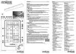
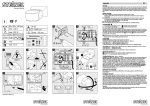
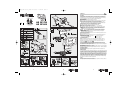
BDAL_HS FE 150-500_DE-GB
22.10.2007
13:25 Uhr
Seite 1
D
DEUTSCH
Das Prinzip
Die Halogen-Strahler mit Funk-Empfänger HS-FE 150 und HS-FE 500 empfängt Funksignale von bis zu
acht Steinel-Sendern mit unterschiedlichen Adressen und schaltet das Licht an. Der Funk-Empfänger
reagiert nur auf Sender, die ihm vorher zugeordnet worden sind. Weitere Informationen zur Einstellung
von Sendern und Empfängern entnehmen Sie bitte der Anleitung IMPULSER-System.
Sicherheitshinweise
■ Vor allen Arbeiten am Gerät die Spannungszufuhr unterbrechen!
■ Bei der Montage muß die anzuschließende elektrische Leitung spannungsfrei sein. Daher als Erstes
Strom abschalten und Spannungsfreiheit mit einem Spannungsprüfer überprüfen.
■ Bei der Installation dieser Geräte handelt es sich um eine Arbeit an der Netzspannung; sie muß
daher fachgerecht nach den länderspezifischen Installationsvorschriften und Anschlußbedingungen
durchgeführt werden (D- VDE 0100, A-ÖVE/ÖNORM E 8001-1, -SEV 1000)
■ Montieren Sie das Gerät nicht auf gewöhnlich leicht entflammbaren Oberflächen.
■ Der Halogenstrahler darf nicht gegen die Montagewand gerichtet werden.
■ Strahler muß in waagerechter Stellung (± 15°) stehen.
■ Geeignet für Außen- und für Innenräume (Innenräume bis 25° C, ohne Luftzirkulation)
■
Die Montage der Strahler muß so vorgenommen werden, daß für alle möglichen Schwenkpositionen ein Mindestabstand von 1 Meter zur angestrahlten Fläche gewährleistet ist.
■ Die Halogenstrahler sind nur für die Wandmontage und nicht für die Deckenmontage vorgesehen.
Der Abstand zur Decke muß mindestens 1 m betragen.
■I
Im Fall eines Scheibenbruchs, vor Wiederinbetriebnahme unbedingt eine
neue Scheibe einsetzen. Es ist ein 5 mm dickes getempertes Spezialglas
erforderlich (HS-FE 150: 4 mm).
■ Wer sich dem Halogen-Strahler bei Betrieb mit 10% Überspannung für längere Zeit aussetzt,
muß mit Haut- und Augenentzündungen rechnen.
■ Das Strahlergehäuse wird während des Betriebes sehr heiß. Die Ausrichtung des Strahlers nur durchführen, wenn dieser abgekühlt ist.
■ Nur Original-Ersatzteile verwenden
■ Gerät nicht selbst zerlegen. Die Reparatur darf nur durch eine Fachwerkstatt durchgeführt werden.
HS FE 150
HS FE 500
i
1 –
10
Installationshinweise Die Netzzuleitung besteht aus einem 3-adrigen Kabel:
L = Phase (meistens schwarz oder braun)
N = Neutralleiter (meistens blau)
PE = Schutzleiter (grün/gelb)
Projizierte Fläche des Strahlers:
HS-FE 150: ca. 240 cm2
HS-FE 500: ca. 448 cm2
Wichtig: Ein Vertauschen der Anschlüsse führt im Gerät oder Ihrem Sicherungskasten später zum
Kurzschluß. In diesem Fall müssen die einzelnen Kabel identifiziert und neu montiert werden. In die
Netzzuleitung kann selbstverständlich ein Netzschalter zum EIN- und AUS-Schalten montiert sein.
5a , 7a
5 , 7 / Zuleitung Aufputz Zuleitung Unterputz Für eine Auf-Putz-Verdrahtung sind zwei Laschen unten an der Montageplatte vorgesehen. Eine der
beiden Laschen abknicken. Die Kabelöffnung der Montageplatte mit dem Dichtstopfen verschließen.
Diesen durchstoßen und das Kabel durchführen. Wenn das Kabel durchgeführt ist, kann die Montageplatte
angeschraubt und der Anschluß vorgenommen werden.
Betriebsstörungen (Störung / Ursache ➩ Abhilfe)
Ohne Spannung / Sicherung defekt bzw. nicht eingeschaltet, Leitung unterbrochen ➩ neue Sicherung bzw.
Netzschalter einschalten, Leitung mit Spannungsprüfer überprüfen / Kurzschluss ➩ Anschlüsse überprüfen.
Konformitätserklärung
Dieses Produkt erfüllt die Niederspannungrichtlinie 06/95/EG die EMV-Richtlinie 04/108/EG und die
RoHS-Richtlinie 02/95/EG.
Funktionsgarantie
Dieses Steinel-Produkt ist mit größter Sorgfalt hergestellt, funktions- und sicherheitsgeprüft nach geltenden
Vorschriften und anschließend einer Stichprobenkontrolle unterzogen. Steinel übernimmt die Garantie für
einwandfreie Beschaffenheit und Funktion. Die Garantiefrist beträgt 36 Monate und beginnt mit dem Tag des
Verkaufs an den Verbraucher. Wir beseitigen Mängel, die auf Material- oder Fabrikationsfehlern beruhen, die
Garantieleistung erfolgt durch Instandsetzung oder Austausch mangelhafter Teile nach unserer Wahl. Eine
Garantieleistung entfällt für Schäden an Verschleißteilen sowie für Schäden und Mängel, die durch unsachgemäße Behandlung, Wartung oder durch Verwendung von Fremdteilen auftreten. Weitergehende Folgeschäden an fremden Gegenständen sind ausgeschlossen. Die Garantie wird nur gewährt, wenn das unzerlegte Gerät mit kurzer Fehlerbeschreibung, Kassenbon oder Rechnung (Kaufdatum und Händlerstempel),
gut verpackt, an die zutreffende Servicestation eingesandt wird.
Service:
Nach Ablauf der Garantiezeit oder Mängeln ohne Garantieanspruch repariert unser Werkservice. Bitte das
Produkt gut verpackt an die nächste Servicestation senden.
9540000
1
2
3
BDAL_HS FE 150-500_DE-GB
24.10.2007
15:42 Uhr
Seite 1
GB
ENGLISH
Principle
The HS-FE 150 and HS-FE 500 halogen floodlights with wireless receiver can receive wireless signals from
as many as eight Steinel transmitters with different addresses for switching the light ”ON”. The wireless
receiver only responds to transmitters that have first been assigned to it. For further information on setting
transmitters and receivers, please refer to the instructions of the IMPULSER system.
Safety warnings
■ Disconnect the power supply before attempting any work on the unit!
■ During installation, the electrical wiring you are connecting must be dead. Therefore, switch off the
power first and use a voltage tester to make sure the wiring is off circuit.
■ Installing these lights involves work on the mains voltage supply; this work must therefore be carried
out professionally in accordance with national wiring regulations and electrical operating conditions
(D- VDE 0100, A-ÖVE/ÖNORM E 8001-1, -SEV 1000)
■ Do not install the unit on normally flammable surfaces.
■ The halogen floodlight must not be directed at the wall it is mounted on.
■ The light must be set to a horizontal position (± 15°).
■ Suitable for outdoor and indoor use (inndoor max. 25°C as no draft air).
■
The floodlight must be mounted in such a way that when it is set at any possible angle a
minimum distance of 1 metre is guaranteed between the light and the surface it shines on.
■ Halogen floodlights are only intended for wall mounting and not for ceiling mounting. They must be
installed at least 1 m from the ceiling.
■
If the glass cover breaks, always fit a new one before continuing use. Only
replace with special tempered glass in a thickness of 5 mm (HS-FE 150: 4 mm).
■ To avoid inflammation of the skin and eyes, do not expose yourself for any length of time to the halogen
floodlight if it is being operated at a voltage of 10 % above the specified voltage rating.
■ The floodlight housing heats up to a very high temperature while it is switched ”ON”. Only adjust the
angle of the floodlight once it has cooled down.
■ Only use genuine replacement parts
■ Do not dismantle the light yourself. It must only be repaired by a specialist workshop.
HS FE 150
HS FE 500
i
10
1 –
Installation The mains supply lead is a 3-core cable.
L = phase conductor (usually black or brown )
N = neutral conductor (usually blue)
PE = protective-earth conductor (green/yellow)
Projected floodlight area:
HS-FE 150: approx. 240 cm2
HS-FE 500: approx. 448 cm2
Important: Getting the cable connections crossed will produce a short circuit in the unit or in your fuse
box. In this case, you must identify the individual cables and re-connect them. A mains switch for switching
the light ”ON” and ”OFF” can of course be installed in the mains lead.
7a
5 , 7 / Surface wiring 5a , Concealed wiring Underneath the mounting plate you will find two lugs for surface wiring. Break off one of the two lugs. Use
the sealing plug to close off the cable opening in the mounting plate. Pierce the sealing plug and feed the
cable through. Once the cable has been pushed through, you can screw the mounting plate to the mounting surface and complete the connection.
Troubleshooting (Fault / Cause ➩ Remedy)
No voltage / Fuse faulty or not switched ”ON”, line broken ➩ New fuse or turn ”ON” mains power switch,
check wiring with voltage tester / Short circuit ➩ Check connections.
Declaration of conformity
This product complies with Low Voltage Directive 06/95/EC, EMC Directive 04/108/EC and RoHS Directive
02/95/EC.
Functional Warranty
This Steinel product has been manufactured with utmost care, tested for proper operation and safety and
then subjected to random sample inspection. STEINEL guarantees that it is in perfect condition and proper
working order. The warranty period is 36 months and starts on the date of sale to the consumer. We will
remedy defects caused by material flaws or manufacturing faults. The warranty will be met by repair or
replacement of defective parts at our own discretion. The warranty does not cover damage to wear parts or
damage and defects caused by improper treatment, maintenance or the use of non-genuine parts. Further
consequential damage to other objects is excluded. Claims under the warranty will only be accepted if the
unit is sent fully assembled and well packed with a brief description of the fault, a receipt or invoice (date
of purchase and dealer's stamp) to the appropriate Service Centre.
Service:
Our Customer Service Department will repair faults not covered by warranty or after the warranty period.
Please send the product well packed to your nearest Service Centre.
9540000
1
2
4
BDAL_FE 8100
24.10.2007
15:31 Uhr
Seite 5
Service
D STEINEL-Schnell-Service
N Vilan AS
Dieselstraße 80-84
33442 Herzebrock-Clarholz
Tel: +49/5245/448-188 · Fax:+49/5245/448-197
www.steinel.de · [email protected]
A I. MÜLLER
Peter-Paul-Str. 15
A-2201 Gerasdorf bei Wien
Tel.: +43/2246/2146 · Fax: +43/2246/25466
[email protected]
PUAG AG
Oberebenestrasse 51
CH-5620 Bremgarten
Tel.: +41/56/6488888 · Fax: +41/56/6488880
[email protected]
STEINEL U.K. LTD.
37, Manasty Road · Orton Southgate
GB-Peterborough PE2 6UP
Tel.: +44/1733/238-265 · Fax: +44/1733/238-270
[email protected]
SOCKET TOOL COMPANY
8, Queen Street
IRL-Dublin 7
Tel.: +353/1/8725433 · Fax: +353/1/8725195
[email protected]
F DUVAUCHEL S.A. · ACTICENTRE - CTR 2
Rue des Famards - Bat. M - Lot 3
F-59818 Lesquin Cedex
Tél. +33/3/20 30 34 00 · Fax: +33/3/20 30 34 20
www.duvauchel.com · [email protected]
VSA HEGEMA B.V.
Christiaan Huygensstraat 4
NL-3291 CN Strijen
Tel.: +31/78/6744444 · Fax: +31/78/6743113
[email protected]
Tvetenveien 30 B
N-0666 Oslo
Tel.: +47/22725000 · Fax: +47/22725001
[email protected]
PANOS Lingonis + Sons O. E.
Aristofanous 8 Str.
GR-10554 Athens
Tel.: +30/210/3212021 · Fax: +30/210/3218630
[email protected]
EGE SENSÖRLÜ AYDINLATMA ‹TH.
‹HR. T‹C. VE PAZ. LTD. fiT‹.
GERSAN SAN. S‹TES‹ 659. SOKAK · NO:510
BATIKENT/ANKARA
Tel.: +90/312/2571233 · Fax: +90/312/2556041
www.egeaydinlatma.com
[email protected]
ELNAS s.r.o.
Oblekovice 394
CZ-67181 Znojmo
Tel.: +420/515/220126 · Fax: +420/515/244347
[email protected] · www.elnas.cz
LANGE ŁUKASZUK Sp.j.
Byków 25a
PL-55-095 Mirków
Tel.: +48/71/3 98 08 861 · Fax: +48/71/3 98 19
[email protected] · www.langelukaszuk.pl
H DINOCOOP KFT.
Radvány u. 24
H-1118 Budapest XI
Tel.: +36/1/3 19 30 64 · Fax: +36/1/3 19 30 66
www.dinocoop.hu · [email protected]
KVARCAS
Neries krantine 32
LT-48463, Kaunas
Tel.: +370/37/408030 · Fax: +370/37/408031
[email protected]
FORTRONIC AS
Teguri 45c
EST 50113 Tartu
Tel.: +372/7/475208 · Fax: +372/7/367229
[email protected]
LOG Zabnica D.O.O.
Podjetje Za Trgovino · Srednje Bitnje 70
SLO-4209 Zabnica
Tel.: +386/42/312000 · Fax: +386/42/312331
[email protected]
Neco s.r.o.
Ruzová ul. 111
SK-01901 Ilava
Tel.: +421/42/4 44 14 55
Fax: +421/42/4 44 14 56
[email protected]
STEINEL Trading s.r.l.
Str. Lunga 123
RO-507055 Cristian-Brasov
Tel.: +40/2 68/25 74 00 · Fax: +40/2 68/25 76 00
www.steinel.ro · [email protected]
Daljinsko Upravljanje d.o.o.
B. Smetane 10
HR-10 000 Zagreb
Tel.: +3 85/1/3 88 02 47 · Fax: +3 85/1/3 88 02 47
[email protected]
www.daljinsko-upravljanje.hr
Ambergs SIA
Brivibas gatve 195-16
LV-1039 Riga
Tel.: +3 71/7/55 07 40 · Fax: +3 71/7/55 28 50
www.ambergs.lv · [email protected]
IT und R GmbH
Kuibyshev Str. 78
RUS-620026 Ekaterinburg
Tel.: +7/34 32/24 23 23 · Fax: +7/34 32/61 61 65
[email protected]
VAN SPIJK AGENTUREN B.V.
Postbus 2, NL-5688 ZG Oirschot
De Scheper 260, NL-5688 HP Oirschot
Tel.: +31/499/571810 · Fax: +31/499/575795
[email protected] · www.vanspijk.nl
B VSA handel Bvba
Fabriekstraat 145
B-3900 Overpelt
Tel.: +32/11/660720 · Fax: +32/11/660729
[email protected] · www.vsahandel.be
L A. R. Tech.
19, Rue Eugène Ruppert, Cloche D’Or · BP 1044
L-1010 Luxembourg
Tel.: +352/49/3333 · Fax: +352/40/2634
[email protected]
I THOELKE DISTRIBUZIONE S.N.C.
Via Adamello 2/4
I-22070 Locate Varesino (Como)
Tel.: +39/331/836911 · Fax: +39/331/836913
[email protected]
E SAET-94 S.L.
C/ Trepadella, n° 10 · Pol. Ind. Castellbisbal Sud
E-08755 Castellbisbal (Barcelona)
Tel.: +34/93/772 28 49 · Fax: +34/93/772 01 80
[email protected]
P Pronodis-Soluções Tecnológicas, Lda
Rua do Caseiro no 87 A/B · Vilar
P-3810-078 Aveiro
Tel.: +351/234/484031 · Fax: +351/234/484033
[email protected]
S KARL H STRÖM AB
Verktygsvägen 4
S-55302 Jönköping
Tel.: +46/36/31 42 40 · Fax: +46/36/31 42 49
www.khs.se · [email protected]
BROMMANN
Ellegaardvej 18
DK-6400 Sønderborg
Tel.: +45/7442 8862 · Fax: +45/7443 43 60
[email protected]
Oy Hedtec AB
Mänkimiehentie 4
FIN-02780 Espoo
Tel.: +358/9/682881 · Fax: +358/9/68284278
www.hedtec.fi · [email protected]
4
SVETILNIKI
Str. Malaya Ordinka, 39
RUS-113184 Moskau
Tel.: +7/95/2 37 28 58 · Fax: +7/95/2 37 11 82
[email protected]
5