1
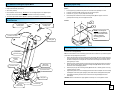
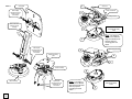
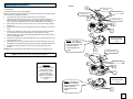
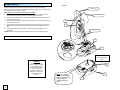
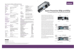
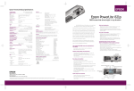
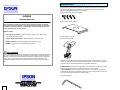
Hardware description
The Projector Mount utilizes the following hardware. Note that the letters associated with the hardware on this
list correspond to the letters listed in the instructions for each installation method. If any of the following
hardware is missing STOP. Contact Epson for proper hardware.
A. Four (4) M4 x 10 (mm) Phillips screws (supplied)
ELPHB800
Installation Instructions
B. One (1) mounting bracket (supplied)
The entire installation instructions should be fully read and understood, including all of the safety
precautions, before beginning installation. The installation instructions should be read, understood
and followed to prevent personal injury or property damage. Keep these installation instructions in
an easily accessible location for future reference.
Installation methods:
° Fixed Height Ceiling Installation— Best for short ceilings, eight (8’) or lower. Removal of the
center adjustable suspension in needed.
° Adjustable Height Ceiling Installation—Best for high ceilings, nine (9’) feet or higher.
C. Digital Projector (not included)
D. Assembly mount (supplied)
° Wall Mount Installation—For installing the Digital Projector Mount on a rear wall.
° ELPMBAPL—(Optional) 26" to 47" Adjustable height ceiling adapter.
Before Installation
The wall or ceiling where you want to install the digital projector must be capable of supporting a weight that is
five (5) times the weight of the projector you are installing. Consult the projector’s documentation for weight
specifications. The ceiling structure must be capable of supporting a max weight of 25 lbs., the weight of the
projector. If not, the ceiling must be reinforced. Proper installation procedure by qualified personnel as
outlined in the installations instructions must be adhered to. Failure to do so could result in serious personal
injury.
NOTE: Hardware item (E) is what secures the Digital Projector Mount to a simple wood stud on your wall
ceiling. For all installations other than single wood mounting make sure you consult with your local hardware
store staff for the type of hardware that works best for your installation environment.
E. SINGLE WOOD STUD: If mounting on a single wood stud use the three (3) #14 x 2" Lag screws (supplied)
Use the mounting points on the center of the plate as indicated in the assembly diagram.
° SOLID STRUCTURE: If mounting to a solid structure use four (4) 5/16" x 2" Lag screws or commercially
available hardware (depending on the installation requirements). Use the mounting points found on the outer
points of the mounting plate as indicated in the assembly diagram.
F. Allen wrench (supplied)
1
Tools Needed for Installing the Projector Mount
Getting the projector ready
You need the following tools to install the Projector Mount:
Before you start the installation process, prepare your Digital Projector by performing the following steps
(FIGURE 1).
• Phillips head screwdriver (not included)
• Allen wrench (included)
1.
Turn the projector (C) upside down and place it on a clean flat surface, preferably on a towel.
• Drill for installation environment only - do not use a drill on the Digital Projector or the Digital Projector
Mount) and drill bit to match the hardware for your installation environment (not included).
2.
Locate the mounting bracket (B) and align it over the holes on the projector.
3.
Locate the four (4) 4 (mm) x 10 (mm) Phillips head screws (A).
4.
Use the Phillips head screwdriver to secure the mounting bracket (B) to the projector via the four
• The commercially available hardware (E) that is required by your installation environment (not included)
(4) Phillips head screws (A). Do not over-tighten the screws.
Mount Overview
FIGURE 1
(4) Solid structure
mounting points
A
(3) Single wood stud
mounting points
B
NOTE: The shape of
each mount is different.
Align each bracket hole
with the projector
mounting point and
attach.
(2) Cable access points
Ceiling plate
C
Fixed height Ceiling installation (optional installation)
Complete the following steps to install the projector mount and projector on your ceiling. This installation
works best with low ceilings (FIGURE 2).
(2) Adjustable
suspension screws
Note: Look at the bottom of the mount assembly (D) and locate the arrow. Make sure you install the projector
mount with the arrow pointing toward your screen.
1.
Remove the upper plate and the center extension from the assembly (D) secure the upper plate to the
ceiling structure using the commercially available hardware (E) suitable for your environment. Replace
the bottom assembly to the secured plate. Be sure that the mount assembly screen indicator arrow is
pointing toward your screen.
2.
Replace the mount assembly with the upper plate and fully raise the safety knob and tension knobs all
the way. Carefully raise the projector (C) with the mounting bracket (B) attached and insert it into the
bottom of the mount assembly (D) by its tabs.
3.
Rotate the projector (C) with the mounting bracket (B) attached 180º so that the projector’s focus ring
is pointing toward your screen.
4.
Align the safety knob on the mount assembly (D) with the end of the arrow-shaped slot on the mounting
bracket (B) and screw it through the opening to prevent further rotation. Hand-tighten the safety knob.
5.
Hand-tighten the remaining two tension knobs to secure the mounting bracket (B) to the mount
assembly (D).
Adjustable
suspension
Safety knobs
(Red indicator)
(2) Tension knobs
(4) Tilt tension screws
Clamp plate
Lower assembly
Screen side
(Yellow indicator)
CAUTION: Check all of the hardware for proper tightness and security. Do not over-tighten the screws.
NOTE: Use the Allen wrench key (F) for the following modification
2
FIGURE 2
Ceiling plate
Wood stud
E
Remove (M8)
Hex head screws, flat
washers and star
lock washers
Center of wood stud
D
Ceiling structure
Remove the center
extension from the
assembly
Insert and rotate 180°
lock down the safety
screw
B
NOTE: The shape of
each mount is different.
Align each bracket hole
with the projector
mounting point and
attach.
C
Remove (M8)
Hex head screws, flat
washers and star
lock washers
Solid ceiling structure
D
Replace the ceiling
plate
A
C
Bottom assembly
B
Bottom assembly
3
Replace (M8)
Hex head screws, flat
washers and star
lock washers
NOTE: The shape of
each mount is different.
Align each bracket hole
with the projector
mounting point and
attach.
Insert and rotate 180°
lock down the safety
screw
C
Adjustable Height ceiling Installation
FIGURE 3
E
Complete the following steps to install the projector mount and projector on your ceiling with the optional
suspension adapter.
Wood stud
This installation works best with high ceilings (FIGURE 3).
Note: Look at the bottom of the upper assembly (D) and locate the arrow. Make sure you install the projector
mount with the arrow pointing toward your screen.
6.
Use the Allen wrench (F) to remove the upper plate from the mount assembly (D).
7.
Use the Allen wrench to remove the two screws from the enclosed end of the of the suspension
adapter, and place it into the slotted extension on the upper plate (E). Make sure that the two (2) outer
holes on the suspension adapter align with the holes on the slotted extension on the upper plate.
8.
Replace the two screws removed in step 2 into the two (2) holes to secure the suspension adapter to
the upper plate.
9.
Attach the mount assembly to the suspension adapter and secure them with the two screws removed
in step 1.
10.
Secure the upper assembly to the ceiling using the commercially available hardware (E) suitable for
your environment. Be sure that the upper assembly arrow is pointing toward your screen.
11.
Carefully raise the projector (C) with the mounting bracket (B) attached and insert it into the bottom of
the upper assembly (D) by its tabs.
12.
Rotate the projector (C) with the mounting bracket (B) attached 180º so that the projector’s focus ring
is pointing toward your screen.
13.
Align the safety knob on the mount assembly with the end of the arrow-shaped slot on the mounting
bracket (B) and screw it through the opening to prevent further rotation. Hand-tighten the safety knob.
14.
Hand-tighten the remaining two tension knobs to secure the mounting bracket to the amount
assembly.
CAUTION: Check all of the hardware for proper tightness and security. Do not over-tighten the screws.
Center of wood stud
Ceiling structure
D
Adjustable screws
B
C
B
Insert and rotate 180°
lock down the safety
screw
NOTE: The shape of
each mount is different.
Align each bracket hole
with the projector
mounting point and
attach.
NOTE: Use the Allen wrench key (F) for the following modification
C
Solid ceiling structure
E
Adjustable screws
D
WARNING
B
When using the optional
extension adapters and making
a height adjustment while
secured to the wall or ceiling do
not remove the screws
completely from the extension.
Failure to do so could result in
injury and damage to the
projector.
C
B
NOTE: The shape of
each mount is different.
Align each bracket hole
with the projector
mounting point and
attach.
Insert and rotate 180°
lock down the safety
screw
C
4
Wall Mount Installation
FIGURE 4
Complete the following steps to install the projector mount and projector to your wall. (FIGURE 4)
Wall wood stud
Note: Look at the bottom of the upper assembly (D) and locate the arrow. Make sure you install the projector
mount with the arrow pointing toward your screen.
NOTE: Follow step 3 to secure the extension to the mount assembly.
15.
Secure the upper plate to the wall using the commercially available hardware (E) suitable for your
environment. Be sure that the screen indicator arrow is pointing toward your screen.
16.
Carefully raise the projector (C) with the mounting bracket (B) attached and insert it into the bottom of
the mount assembly by its tabs.
17.
Rotate the projector (C) with the mounting bracket (B) attached 180º so that the projector’s focus rings
is pointing toward your screen.
18.
Align the safety knob on the mount assembly with the end of the arrow-shaped slot on the mounting
bracket (B) and screw it through the opening to prevent further rotation. Hand-tighten the securing
knob.
19.
Hand-tighten the remaining two tension knobs to secure the mounting bracket (B) to the mount
assembly (D).
Wall structure
E
D
Adjustable screws
CAUTION: Check all of the hardware for proper tightness and security. Do not over-tighten the screws.
NOTE: Use the Allen wrench key (F) for the following modification
B
C
Insert and rotate 180°
lock down the safety
screw
WARNING
When using the optional
extension adapters and making
a height adjustment while
secured to the wall or ceiling do
not remove the screws
completely from the extension.
Failure to do so could result in
injury and damage to the
projector.
5
B
NOTE: The shape of
each mount is different.
Align each bracket hole
with the projector
mounting point and
attach.
C
A